Finished electric rig, bye bye propane!

Homebrew Talk - Beer, Wine, Mead, & Cider Brewing Discussion Forum

Help Support Homebrew Talk - Beer, Wine, Mead, & Cider Brewing Discussion Forum:

This site may earn a commission from merchant affiliate links, including eBay, Amazon, and others.
I'm not an electrical engineer, just a lowly physicist/chemist, but there's a lot of bad advice being thrown around in this thread. I'm no safety nazi either, but you really need to change your design.

Apply nodal analysis to the nearest junction before the switch-element loop. You will see that the switch as a whole will actually see 45.8A. This follows from Kirchhoff's circuit laws. Each leg will have to carry the full loop current, and since there's two legs you get a big number. That's semantics, though.

What really does matter is not current or voltage, but the amount of power dissipation that the contacts on the switch can handle. When the switch is in the closed state it has some small internal resistance, much like wiring. This resistance causes heating based on power (energy per unit time) pushed through it. Depending on the design and materials there is a certain amount of heat (energy) that can move out of the contacts in a given amount of time (flux). If the amount of heat generated is too large the device melts, catches on fire, or otherwise breaks down. This is why it is generally considered bad, and usually against code, to run NMB inside conduit. The additional layers impede heat flow away from the wires. So that's why the switch is derated with respect to current at higher voltages, it generated too much heat.

That switch is not rated to handle the amount of power you are pushing through it. You should upgrade or use that switch to control a DPST contactor. When choosing a replacement switch or contactor for your application you need to find one that has a contact rating of at least 26 A at 240 V. Your current switch may be working fine for now because there's always a safety factor in those ratings, but it could also be on the verge of failure. If you want to keep it just add a 30 A 240V contactor with a 120 V coil. Disconnect all the legs from your switch and run them through the contactor. Run one hot leg from your hot buss through the switch, then to the contactor's coil. Run a neutral from your neutral bus to the other side of your contactor and you're set. It you want to you can also install a small inline fuse on the hot leg which will allow you to run smaller wire after the fuse.

Wow. Way over my head, but the message is clear. Guess I need a contactor/coil. Could you provide a link to a suitable option and draw me a simple wire diagram? Would be very much appreciated. Rather buy more now than pay more later....
 
Apply nodal analysis to the nearest junction before the switch-element loop. You will see that the switch as a whole will actually see 45.8A. This follows from Kirchhoff's circuit laws. Each leg will have to carry the full loop current, and since there's two legs you get a big number. That's semantics, though.

I'm not sure I follow you here. Are you saying that current flowing into the element and current flowing out of the element should be added togeter to get the total current in the circuit?

Another way to look at switch capacity is to multiply the Current and Voltage ratings together. That gives you a maximum Wattage you can switch.
 
So can i get a second OK for using these on camco 5500w elements? https://www.elecdirect.com/product.aspx?id=2873

Those look like the same contactors that are sold on auberins website (both specs and phenotypical) - if you are getting two from the site you listed they might be cheaper, but aurberins is a pretty close in price. To me it looks like the have renamed the P/N; i.e. the contactor itself is still the "pioneer breaker" brand contactor just being resold under a different "seller's P/N".

That one you have looks right spec wise, but I know the auberins one is a good quality product. I have used 4 pioneer breaker contactors like those sold on auberins in my 1.5 year old build as well as my most current build (still work).
 
Here's a good one for you application. And a pretty good price as well.

If you want to go with a switch this one will work. But it's more than double the cost of adding a contactor. Another thing to consider is that by adding a contactor your switch, which is the part you touch, will only be carrying 120V, adding a layer of protection. It also introduces an additional point of possible failure, though, so you'll have to make that call.

If you want to go with the contactor here's the wiring diagram. You will leave your current SSR leg alone, and add the contactor using the wires that are currently running through your switch. Then wire the switch to the coil of the contactor as shown. I've included the 0.5 A fuse in case you want to throw it in there, which I recommend, and use lighter wire downstream of the fuse.
 
I'm not sure I follow you here. Are you saying that current flowing into the element and current flowing out of the element should be added togeter to get the total current in the circuit?

Another way to look at switch capacity is to multiply the Current and Voltage ratings together. That gives you a maximum Wattage you can switch.

No, if you consider the element the current is the current, it's a linear circuit element so the current is the same at any point in the element. Like I said it was a semantic argument. For the switch, there are two linear elements, one for each leg that each sees the same current as the element, so for the switch as a whole the absolute current is the sum of the magnitude of the two legs.
 
No, if you consider the element the current is the current, it's a linear circuit element so the current is the same at any point in the element. Like I said it was a semantic argument. For the switch, there are two linear elements, one for each leg that each sees the same current as the element, so for the switch as a whole the absolute current is the sum of the magnitude of the two legs.

You're right. The question is, is the current rating for the dual pole switch per pole, or for the whole switch.

(by the way, calling on kirchoff's current loops for this was super overkill, I thought it was funny though :) )
 
You're right. The question is, is the current rating for the dual pole switch per pole, or for the whole switch.

It's the rating per path through the switch, so yea, you could run two 15 A legs through his switch. But he's running two 26 A legs through it, which isn't a good thing.

Yea, Kirchhoff's was over the top, but that's how I roll. I like it when I can help people understand why things are the way they are. My goal is a PhD in biophysics, then get a professorship. I love academia.
 
So can i get a second OK for using these on camco 5500w elements? https://www.elecdirect.com/product.aspx?id=2873

They look fine to me, on the product datasheet near the end you'll see the full-load rating in the table. As long as the resistive rating is higher than the current draw of your elements (it is) and the voltage is below the maximum (it is) then they're rated for what you want to do.
 
trigger said:
No, if you consider the element the current is the current, it's a linear circuit element so the current is the same at any point in the element. Like I said it was a semantic argument. For the switch, there are two linear elements, one for each leg that each sees the same current as the element, so for the switch as a whole the absolute current is the sum of the magnitude of the two legs.

Ohh, I see what you're saying. Electrical ratings generally apply to each pole though ...thank god or that could be confusing.
 
passedpawn said:
You're right. The question is, is the current rating for the dual pole switch per pole, or for the whole switch.

(by the way, calling on kirchoff's current loops for this was super overkill, I thought it was funny though :) )

It's per pole or I've been doing things wrong for a long time..

Me and Kirchoff sucked down quite a few brews together back in the day.
 
Ohh, I see what you're saying. Electrical ratings generally apply to each pole though ...thank god or that could be confusing.

Yea, I appreciate now that what I wrote could be misleading, I was trying to clarify the issue of whether the switch with respect to the manufacturers rating sees the full load current or half the load current per leg, as some had suggested earlier. I apologize for confusing anyone.

The take away is that whatever current is flowing through the element must be less than the manufacturer's published contact current rating at the operating voltage regardless of how many legs are running through the switch.
 
I sent a PM to P-J. Here is his response:

P-J said:
The switch is rated for 15A at 250V. This rating is for the voltage/current across the switch contacts when the switch is opened or closed.

The switch is rated for 25A at 120V. This is the rating from contact to contact within the switch. Because the switch is being used to break both poles of a 240V feed simultaniously, the switch will never see more than 120V across the switch contacts as both are broken at the same instant. The switch rating is for 25A at 120V. It will do the job very well with the wiring illustration (drawing) that I provided.

Please keep in mind that there are many, many opinions out there. A lot of 'em without...
Nevermind.

The switch I chose for THIS application will do the job very well without concerns.

Sorry for your battle. I choose to not reply to the thread. You can certainly post my opinion. That's up to you.

Wishing you the best.

P-J
 
So just an update...

I decided to purchase a contactor. I bought the 40A from Auber. Just browsing through the site, I found that they sell a 40A external heat sink for SSR's. Bought that too. It will be large enough to cover the ugly fan hole in my control panel and give me a watertight enclosure again.

I would watch that sink on that nema box carefully for your first couple brews to see how it disperses the heat and if it affects the plastic, depending on how you mount it.

You will like the contactors - easy to wire, safe, reliable.
 
I would watch that sink on that nema box carefully for your first couple brews to see how it disperses the heat and if it affects the plastic, depending on how you mount it.

You will like the contactors - easy to wire, safe, reliable.

How about a bead of silicone between the heat sink and the enclosure? Will that help? I bought the larger heat sink (4"x4"x2"), so that should help. I'll definitely keep an eye on it though. Thanks for the heads up.
 
How about a bead of silicone between the heat sink and the enclosure? Will that help? I bought the larger heat sink (4"x4"x2"), so that should help. I'll definitely keep an eye on it though. Thanks for the heads up.

The pure silicone at HD has an operating temp of 400F so it could provide a buffer. But you want to make sure the SSR/sink is securely fastened to the box - not sure I would want only silicone responsible for holding it in place.

Jbweld is another possibility, but might be too permanent.

You might be ok with the larger sink - just keep an eye out :D

Yeah, that's the silicone I have. The heat sink will be mounted by 4 screws (1 at each corner). I can't wait to finally get this thing fired up and running. It will probably take a while to get familiar with the PID, so I'll do a wet test this weekend to play around. Any easy way to set up the PID? I know I have to switch the Sensor input (Sn) to 21 for my RTD PT100 sensor and do an input offset (Pb) after calibrating in an ice bath, but I'm kind of lost after that.

Does anyone have a good step-by-step guide to setting up a PID? I have an Auber 2352.
 
The pure silicone at HD has an operating temp of 400F so it could provide a buffer. But you want to make sure the SSR/sink is securely fastened to the box - not sure I would want only silicone responsible for holding it in place.

Jbweld is another possibility, but might be too permanent.

You might be ok with the larger sink - just keep an eye out :D

Here's what I did. Used a couple of cheap elbows from HD, drilled holes in heat sink.

Toolbox_Heatsink.JPG
 
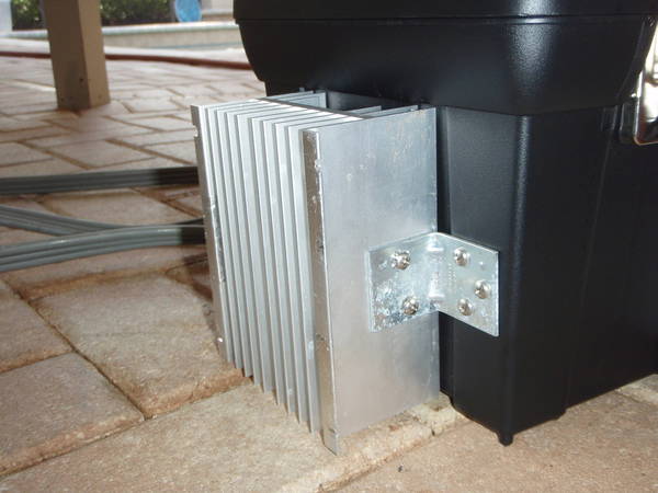
How is your SSR(s) attached to the heat sink?

SSRs are screwed into the heatsink (that heat sink is made for 2 standard SSRs, and has tapped holes for easy mounting; I didn't have to do anything really). The terminals of the SSRs then feed through a cutout in my toolbox. Those are two dual SSRs. You can sort of see the SSRs and the cutout here:

P6270015.JPG
 
Yeah, that's the silicone I have. The heat sink will be mounted by 4 screws (1 at each corner). I can't wait to finally get this thing fired up and running. It will probably take a while to get familiar with the PID, so I'll do a wet test this weekend to play around. Any easy way to set up the PID? I know I have to switch the Sensor input (Sn) to 21 for my RTD PT100 sensor and do an input offset (Pb) after calibrating in an ice bath, but I'm kind of lost after that.

Does anyone have a good step-by-step guide to setting up a PID? I have an Auber 2352.

For setting up your PID I have listed instructions on my build thread. There are links to key parts you can click on post#1, in particular the one for "How to configure, autotune, etc your PID" - see post #307 for the step by step for that auber PID (I have three of the same ones). Remember to reset your A/M for the last step after autotune so you can use both the automatic and manual modes.

Nice passedpawn - I like that better than the silicone only prospect.

goocher if you don't have a tap, you can get one at sears for like 12 bucks for the smaller sized screws. Grab a 8 32 bag of screws from HD for .99 and you will be off to the races (that is how I did my ssr to heat sink screw connections).


:off:passedpawn - saw that PFT44 Turbine Meter & Display you told bsquared about. That thing looks really cool and would love that to cure my lack of sight glasses on my HLT and BK. I will have to keep an eye out for a good price on them. Have you used yours yet?
 
For setting up your PID I have listed instructions on my build thread. There are links to key parts you can click on post#1, in particular the one for "How to configure, autotune, etc your PID" - see post #307 for the step by step for that auber PID (I have three of the same ones). Remember to reset your A/M for the last step after autotune so you can use both the automatic and manual modes.

Thank you very much. Big help. You even tell me how many times to hit the set button. Sweet.
 
:off:passedpawn - saw that PFT44 Turbine Meter & Display you told bsquared about. That thing looks really cool and would love that to cure my lack of sight glasses on my HLT and BK. I will have to keep an eye out for a good price on them. Have you used yours yet?

I posted some info in the Electrical Components thread.
 
Well I had my first run using my new system. Besides a few pump priming issues, it went off without a hitch. I was especially blown away with how clear the first runnings were! There might be something to this whole mash recirculation thing... And how clear it was coming out of the boil kettle. I've never had wort this clear. I'll attribute this to mash recirc and having DIY hopstoppers. Here's a picture before it hit the fermenters. It's my house pale ale. I got 75% efficiency with a single batch sparge. Not too shabby. Better than I've ever done before.

Edit: How do I flip pictures? The picture still serves its purpose, but that bugs me..

OG Wort.jpg
 
Goocher said:
Well I had my first run using my new system. Besides a few pump priming issues, it went off without a hitch. I was especially blown away with how clear the first runnings were! There might be something to this whole mash recirculation thing... And how clear it was coming out of the boil kettle. I've never had wort this clear. I'll attribute this to mash recirc and having DIY hopstoppers. Here's a picture before it hit the fermenters. It's my house pale ale. I got 75% efficiency with a single batch sparge. Not too shabby. Better than I've ever done before.

Edit: How do I flip pictures? The picture still serves its purpose, but that bugs me..

<img src="https://www.homebrewtalk.com/attachment.php?attachmentid=59877"/>

Yeah, it's not possible to take a gravity reading at that angle;) I think you have to rotate them before you upload.

I was so impressed with my clear wort too. Then I added yeast and it got all cloudy. It does clear again eventually ...
 
Back
Top