• Please visit and share your knowledge at our sister communities:
  • If you have not, please join our official Homebrewing Facebook Group!

    Homebrewing Facebook Group

Facelift for my control panel

Homebrew Talk

Help Support Homebrew Talk:

This site may earn a commission from merchant affiliate links, including eBay, Amazon, and others.
My pump is also before my rims so it pushes the wort through it...

I did make another change to my system though... I now used one of theses flow switches as a safety to prevent the rims element from being on without flow. Its all stainless internally and out and allows much more flow.

https://www.ebay.com/itm/Liquid-flow-switch-sensor-NPT-1-2-inch-female-female-Stainless-Steel-FSS-N1FF-SS/222638041158?ssPageName=STRK:MEBIDX:IT&_trksid=p2057872.m2749.l2649

I did actually put this switch on the exit of my rims leading to my flow meter and top of the mashtun. This was just to make it easier to drain the rims after brewing and when cleaning as this valve actas as a bit of a check valve as well and I pump backwards through my rims to fill my mash tun with strike water.
 
Ok so full power is getting to the motor. Now read it at 75, 50, and 25% using that RMS function.

My FM is before the RIMs tube, but after the proportional valve.

So it went down by about 1 V each time I dropped by 25%. So 75 was about 23V, 50 was about 22V, and 25 was about 21V. I even checked 5% and that was about 20V. 0% obviously went to 0V.
 
@augiedoggy Do you pump strike water through your pumps in the opposite direction they are suppose to go, or do you disconnect your pump from the mashtun before you pump stike water backwards into the mashtun? I hope that makes sense, lol. I will have to take a look at some of your setup pics again as well.
 
All my pumps are permanently plumbed into my Hardline manifold or attached to my plate chiller. I do have some hoses but they are switched around for cleaning and not during the brewing process. When I brew I only turn a couple three way valves during the process. Yes I push liquid backwards just fine through pumps that are off by using a different pump somewhere else. In this case the hlt pump pushes through the rims manifold backwards until my strike water level is met. Then I turn the 3 way valve to divert the flow from rims output to the HLT to the flowmeter and top of my MT for recirculation. When that's done I turn a different 3 way valve to revert wort to the BK and yet another t way valve to divert hlt water to the sparge arm at the same rate... (20-25% on pwm).
I have 3- 3way valves in total.
 
So it went down by about 1 V each time I dropped by 25%. So 75 was about 23V, 50 was about 22V, and 25 was about 21V. I even checked 5% and that was about 20V. 0% obviously went to 0V.
how did your actual flow speed react? I can take mine from 3 gpm down to about 1 gpm with mine and less with pulling through the grainbed as a restriction.

if you dont have one I suggest a cheap flowmeter... I use the analog optical sight gauge style and love it..
 
how did your actual flow speed react? I can take mine from 3 gpm down to about 1 gpm with mine and less with pulling through the grainbed as a restriction.

if you dont have one I suggest a cheap flowmeter...

I do not have the flow meter hooked up yet unfortunately. When I was running the test last week for MOSFET with the tan pump, I was doing a leak test with RIMS tube that was not wired yet. I just had a short loop going to make sure there were no leaks, but thought I would mess around with the MOSFET and pump control. Hopefully this weekend I can add the flow meter in and do more testing and calibration. RIMS is now wired as well, so I can also do some testing and configuration of brucontrol for that as well!
 
I was able to do some testing and I still cannot get my MOSFET below 28% without the pump cutting out. I was getting around 3 or 3.5 liters a minute, which I verified with a large marked pitcher. With that said, I could increase the height of the tubing coming out of the RIMS tube and I was able to slow that down to about 1 liter a minute, which was also verified with the large marked pitcher. So utilizing pump head height I can achieve the speed that I need for different situations! Now I just need to find out why GFCI would trip by just having the heating element plugged in, even when now power was going to it. If I cannot figure that out I will create a new thread so that I am not taking up yours! Thanks again for the help and feedback!

By the way, I really cannot wait to see your new 3 BBL system!
 
augie, hope you're still monitoring. Great thread. A lot of really good information; appreciate your time in doing. Curious how your 3 bbl nano brewery is coming. I ran across this in the process of researching replacing my single tier, 3 keggle, 2 pump (chuggers) direct fire (natural gas) system with an electric system which will include RIMS. I really like your idea of using the long cartridge heater. I've pretty much made the decision to replace my chuggers with the 24v tan pumps, so I want to order at least one right now to play around with. Can you suggest a 120 to 24v power supply. I think you said you were using a 7a supply. It seems that all the power supplies I find only have one 24v output and I am assuming I will need at least three for the three pumps. Maybe just haven't looked hard enough. Also any particular pwm controller that you would recommend and how would I use it to test the pump before I complete my electric build? Appreciate any suggestions you might have. Also hope this is an appropriate use of your thread.
 
Also any particular pwm controller that you would recommend and how would I use it to test the pump before I complete my electric build?
I use an Adafruit PRO Trinket for the PWM controller with a 10 turn potentiometer connected to 5v,Gnd, and Analog In "1" (A1). The output PWM pin then just goes to an SSR-->pump. I also use this little chip to operate the element in manual mode. I can expand this to operate as many as 6 PWM devices (only because the arduino only has 6 PWM pins). Here is my simple code if you're interested TRINKET_PWM_CONTROL_V2.
 
currently im using brucontrol to drive all my 24v dc pumps via pwm, I use these boards on my homebrewing system https://www.ebay.com/itm/MOSFET-But...447906?hash=item1c9a568da2:g:HBUAAOSwp5JWaOjr
and I have the TD5 pumps from brewpi for my 3 bbl system which can be driven pwm with the includes potentiometer knob controled board or via brucontrol. I did the water tests last nigh and was impressed the l;ittle pumps are strong enough to push 3 barrels of water into the boil kettle and fill from the bottom against the head pressure. I'll be using them for slow rims and sparge flow.
 
I use an Adafruit PRO Trinket for the PWM controller with a 10 turn potentiometer connected to 5v,Gnd, and Analog In "1" (A1). The output PWM pin then just goes to an SSR-->pump. I also use this little chip to operate the element in manual mode. I can expand this to operate as many as 6 PWM devices (only because the arduino only has 6 PWM pins). Here is my simple code if you're interested TRINKET_PWM_CONTROL_V2.

The PWM frequency is typically 500 or 1000 Hz, depending on the microcontroller chip. That rate is too fast for an SSR, and while it may work in certain ranges, it may skip input cycles too. This rate is good to divide DC power - if you’re switching AC, this rate will really make an AC sine wave very irregular.
 
The PWM frequency is typically 500 or 1000 Hz, depending on the microcontroller chip. That rate is too fast for an SSR, and while it may work in certain ranges, it may skip input cycles too. This rate is good to divide DC power - if you’re switching AC, this rate will really make an AC sine wave very irregular.

The AC SSRs (at least the Crydoms I'm using) are rated at max turn on time of 1/2 cycle, and a max turn off time as 1/2 cycle as well. I would think that for one on/off cycle at 60Hz we would need a max PWM frequency of 60Hz. If you notice the first variable in the code, I've provided a frequency setting. It is currently set at 60Hz, but maybe I'm wrong about the frequency and it should be set to 30Hz? Do you know the recommended frequency for AC pwm? Maybe I'll try 30Hz for a bit and see how it reacts. But I believe you're right that the stock PWM freq. on these things is 1KHz.
 
Sorry... I wasn't clear... First, you should use a MOSFET to drive DC loads off PWM. Since you are using AC, I suggest you get a proportional SSR (caveat: they aren't cheap), and convert the PWM to an analog signal to drive the proportional input. Alternatively, get a variable frequency drive (though your motor will need to be compatible). Would need more info about your hardware to propose more ideas.
 
Sorry... I wasn't clear... First, you should use a MOSFET to drive DC loads off PWM. Since you are using AC, I suggest you get a proportional SSR (caveat: they aren't cheap), and convert the PWM to an analog signal to drive the proportional input. Alternatively, get a variable frequency drive (though your motor will need to be compatible). Would need more info about your hardware to propose more ideas.

Sorry, I suppose I should've been more clear as well.

My pump is 24VDC and is controlled by a DC SSR (which is indeed a MOSFET) with DC input (PWM also). So no problems here, it works beautifuly.
My element is 220VAC 5500W and is drvien by a 50A AC SCR with DC input (PWM in this case).
The pump speed control is beautiful. The element is not perfect. Although it works, and is controllable (the 10 turn pot helps with this, even though i only get 255 steps on my 8bit PWM out) it does not behave totally linearly. I suspect now that is because I was using a 60Hz frequency. In the code, the PWM frequency can be adjusted from 1Hz to 62.5KHz.
I understand now that maybe PWM isn't the preferred option for AC control, but I have to wonder if bringing the frequency down into the 1-10Hz range might result in far better linearity.
 
That is a standard SSR. It should not have a PWM input.
I took your advice after trying to manually control my element with the potentiometer a bit more. The results were worse than I had remembered.
I changed my code. I now have great control over my element controlling with the pot. I made a 10 step program where step one turns the SSR on for 100ms, off for 900ms - and step 9 turn on for 900ms and off for 100ms. Step 0 is "off", step 10 is "on". You could always add as many as 1023 steps i guess, but at 10, the resolution seems good enough. This worked well, thanks for making me revisit this.

Using a DPDT switch I toggle between PID element control to the SSR, or arduino potentiometer control to the SSR.

Click here for code: Element and Pump control, single Arduino, with two pots

So for $10 I have a controller for my pump, and my element.
 
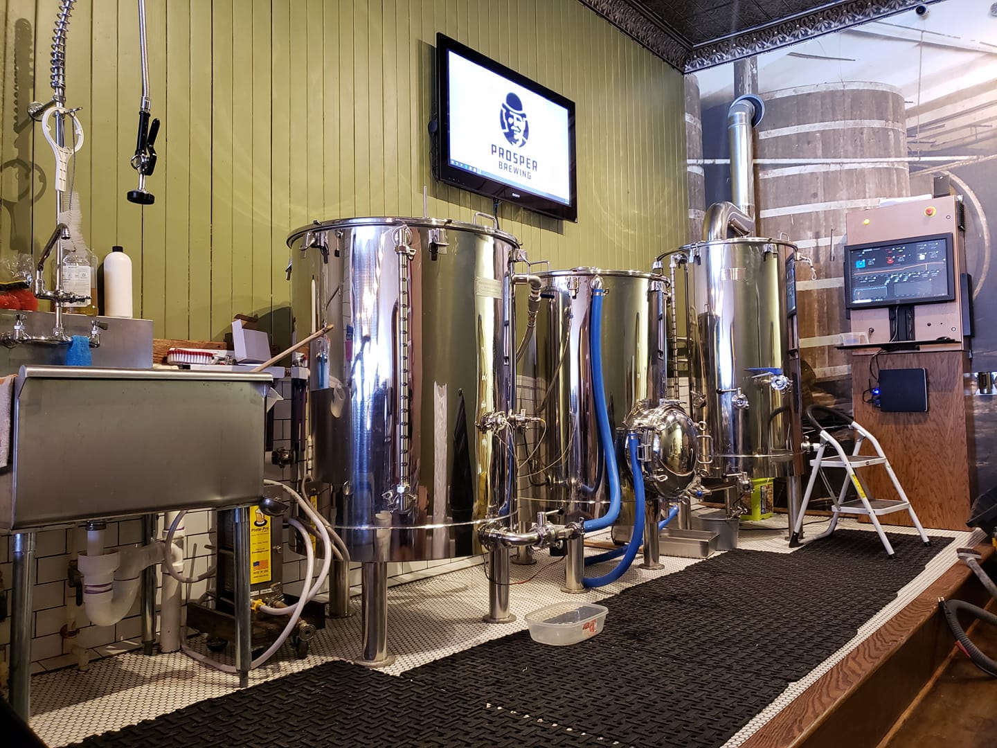
Just a side bar, my 3bbl kettles arrived yesterday.. pretty stoked to get going on my electric panel for that.

Completely random, but when I saw this my brain went "Is this guy a vampire? He's standing in a room with 3 giant reflective objects and managed to NOT catch himself in any of the surfaces"

On topic...
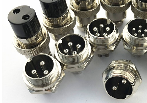
Are you using something like these for your pump connects? Can they handle the power?
 
Completely random, but when I saw this my brain went "Is this guy a vampire? He's standing in a room with 3 giant reflective objects and managed to NOT catch himself in any of the surfaces"

On topic...
Are you using something like these for your pump connects? Can they handle the power?
yes these work fine for pump connections.. my pumps are low voltage 24v dc and only draw a couple amps.. these are more than capable.
 
I want to move to electric keggles to brew in the bag like brew boss
any one can share the electric scheme for basic control panel 1 pump heating element , to control power at heating element and probably time
 
Thanks,

Yes and yes... I forgot to add the grommet so I will be removing the cord to reinstall it... I use a dedicated pump for all three kettles/tun rims and have it setup so I can direct flow with a couple three way valves and dont need to move hoses around during the brewing process... the whole build is under a grand.

I went with these speed controllers available both on ebay and amazon. Now that I have everything working the way I like im streamlining and "cleaning things up" slowly as I'm getting ready for the deticated brew room when we move.

View attachment 231843

View attachment 231844
This looks so much like my setup haha. I have the little solar pumps and everything. Way to be economical ;)
 
milk stout.jpg
So a lot has changed and this is what im brewing on these days. Really just a scaled up version of what I built for the pilot system complete with cartridge heater rims.
 
Last edited:
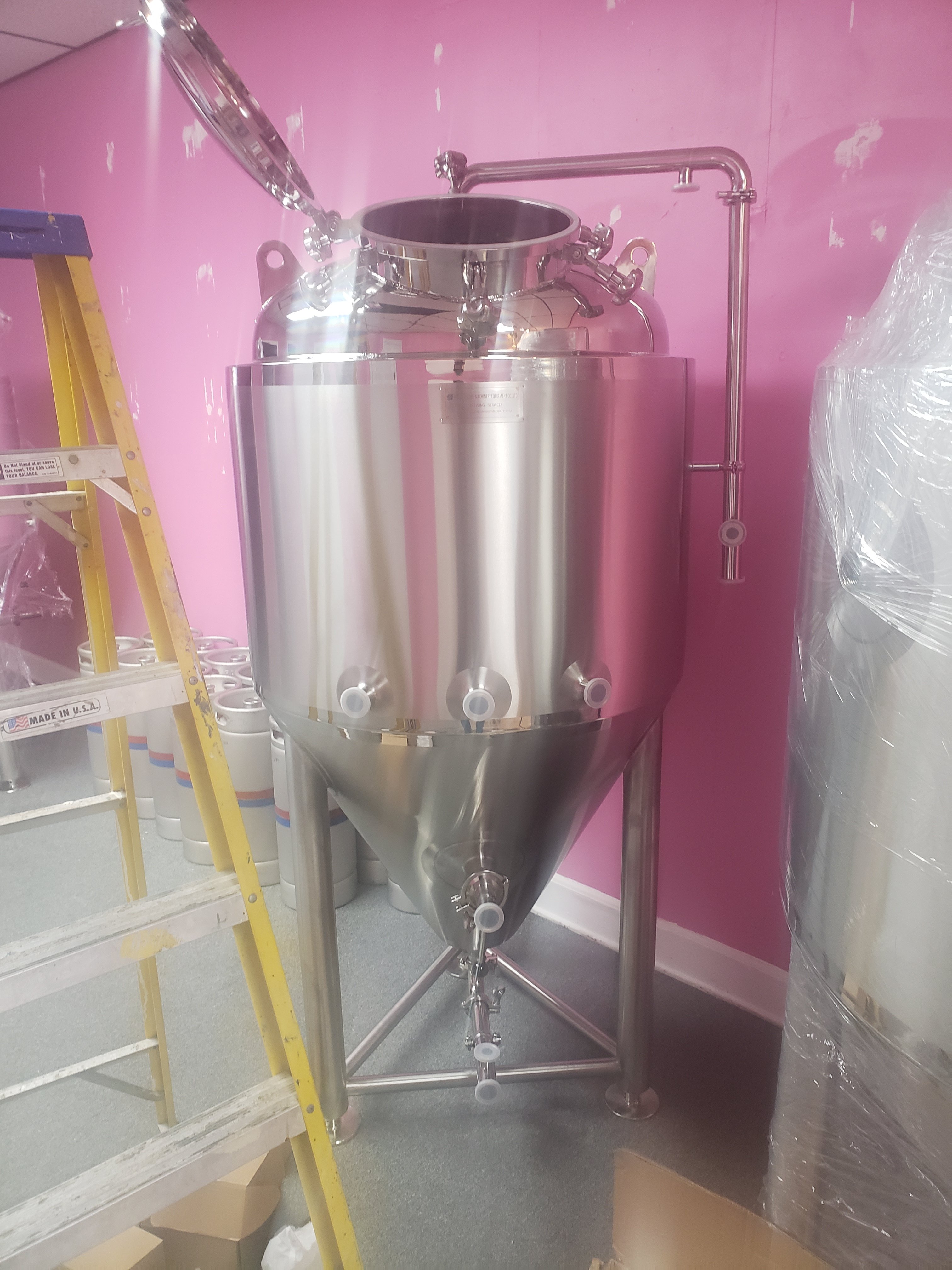
So we received our new unitanks at the brewpub yesterday.. besides having to remove the doorframe to get them in the building I'm ecstatic and couldn't be more satisfied with our purchase.. now I have to beef up our heating and cooling system for the dual zone jackets.
20200228_165626.jpg
20200228_205729.jpg
20200228_205402.jpg
 

Latest posts

Back
Top