• Please visit and share your knowledge at our sister communities:
  • If you have not, please join our official Homebrewing Facebook Group!

    Homebrewing Facebook Group

Electric burners - Any builders out there?

Homebrew Talk

Help Support Homebrew Talk:

This site may earn a commission from merchant affiliate links, including eBay, Amazon, and others.
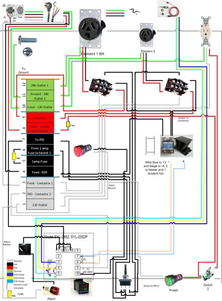
so something like this - pending the alarm. Or... daisy change the two lights, then two contactors then separate for alarm (if I end up getting an alarm :).

Control Panel Box Wiring - Two Elements - Master.jpg
 
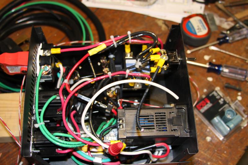
Just curious, does anyone have an idea of how much heat the SSR will put out through the sink? If there is once change I could have made, it would be to get a bigger project box. It is a weee bit crowded. I know I could cut a hole in the box and locate the sink outside, but I am trying to avoid that.

Thanks!
 
FYI Heard back on the wiring for an alarm:

"Connect the hot wire to terminal 13. (you can jump a wire between terminal 9 and 13, if 9 is hot)
Connect both terminals 1 and 14 to one side of the switch.
Connect the other side of switch to one end of the alarm.
Connect the other end of the alarm to the nuetral line ( or terminal 10)"
 
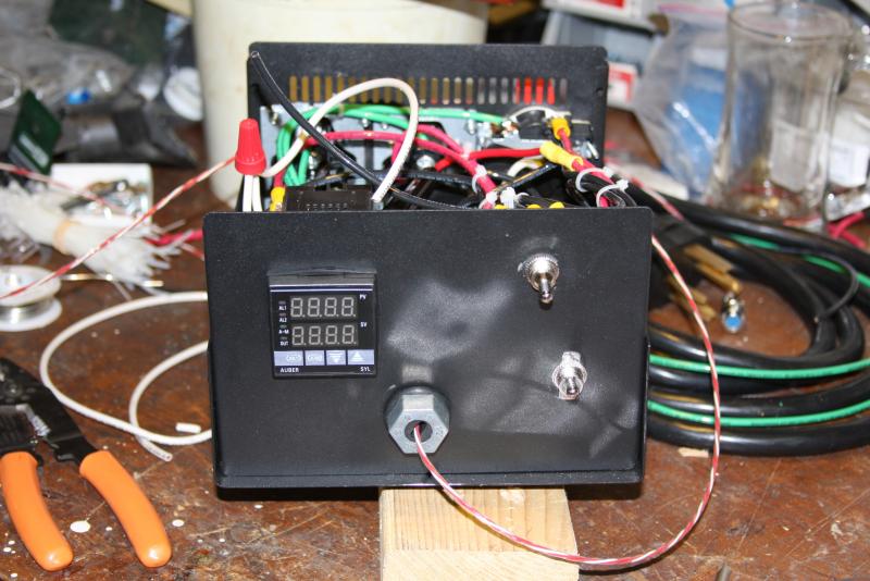
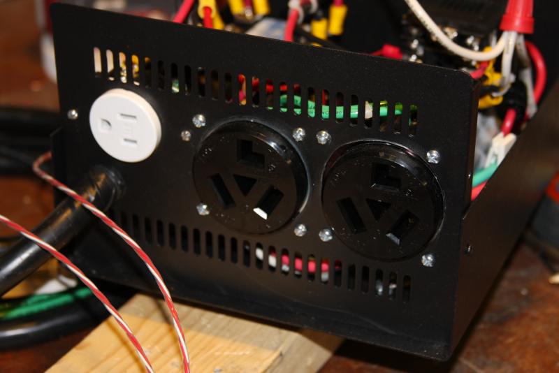
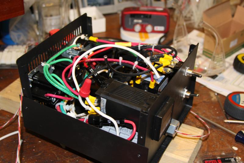
OK - so its been a while, but I thought I would post my progress. Right now it is all wired up (has been for a bit). I am waiting on a couple safety power "on" lights as per walker's suggestion. It is a bit packed in there but I took my time to make it as neat as possible with my fool hardy 10g wiring strategy. It follows my wiring diagram nearly to a T, but I am concerned about the space around the heat sink. That may end up on the outside of the unit if I notice it heating up too much. I will have a light on the face panel when they get in.

Also up for grabs is whether I wired the contactors correctly. I assume it doesn't matter which side gets the hot or the neutral. But if it does, might have to switch it out.

Top switch is on-off-on lateral;
lower right switch is on-off for the pump 125v wall plug
RTD temp exiting in the front (power exterior light will be up and to the right of probe exit hole)


Enjoy!

1.jpg


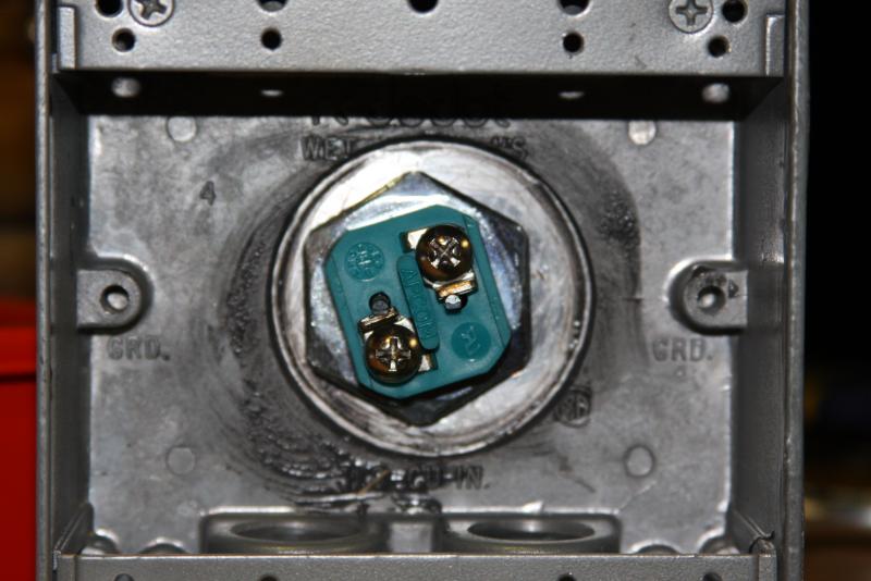
2.jpg


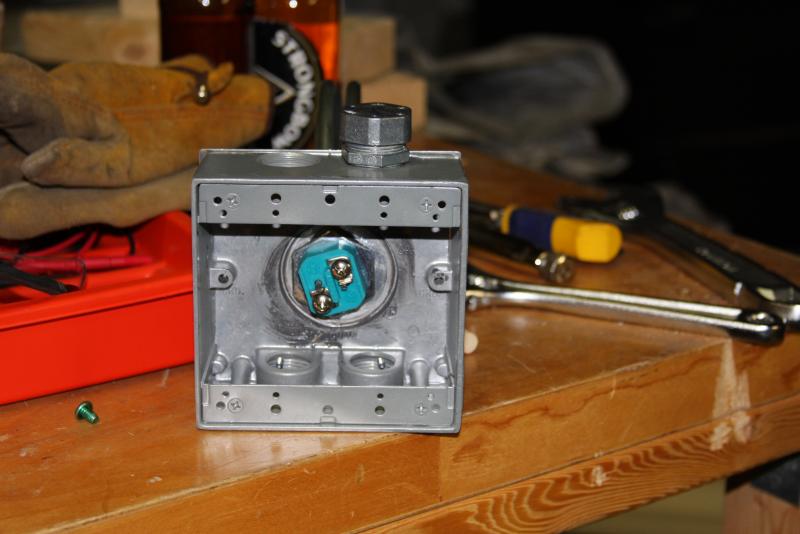
3.jpg


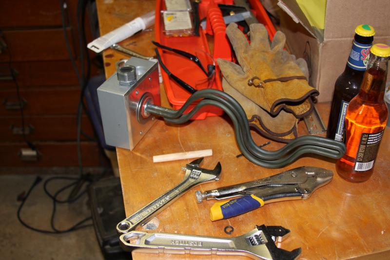
4.jpg
 
And the heating element:

The two bottles in the last pic are rasp and granny smith ciders I made with sorbate and sulfite. They were my bottle bomb test units. They never popped!

5.jpg


6.jpg


7.jpg
 
Do you have enough threads on your element to make it through the kettle wall? I didn't on mine so I had to silicon the box to the kettle.
 
I actually haven't cut a hole in my kettle yet. I have a hole saw and will be going that route because I can't get my hands on a greenlee just yet. However - I am not cutting a hole in the pot until I put in my subpanel (maybe this weekend). Otherwise I can't brew, and we simply can't have that!

So you used silicone to bridge the gap? It looks like i have some good amount of thread, but we will see when it comes time for the actual install. I have a 15 gallon megapot
 
I had to make a large hole in the back of the box to cover the element and wiring, then used silicon to stick it to the kettle since I didn't have enough threads to put it on like you have it.
 
I actually haven't cut a hole in my kettle yet. I have a hole saw and will be going that route because I can't get my hands on a greenlee just yet.
...
Careful with using a hole saw as it will cut a 'not so clean' hole. I'd suggest using a Step Bit to do the job. There is a Harbor Freight near you and the tool is fairly cheap ($20).
 
It looks like I will be able to thread it on just barely. If not, it will be time to get creative ;)

The mega pot is pretty thick walled. I will measure the clearance of the threading and what I anticipate the bend in the pot to be before I cut. Right now, since I am waiting for the ground to ease up with snow so I can retrench my new power feed to the subpanel, I sort of hit a wall with the project.
 
PJ - do you think the step bit will cut a cleaner hole? I was apprehensive about the step bit because it looks like it will jostle around more (with that side groove). There is a harbor freight about 10-15 minutes from where I work.
 
The hole saw cut a pretty nice hole in the face plate for the element, darn near perfect in sizing. I know the stainless would be harder, longer and require more patience, but since the hole was so nice.... was thinking I would cut it, debur and go from there.
 
It should cut a very smooth hole. I have a set and use it often. I'd drill or punch an undersized hole first and then use the step bit to bring it to size. Lots of pressure, oil and go slow. You do not want the bit to spin freely.
 
It should cut a very smooth hole. I have a set and use it often. I'd drill or punch an undersized hole first and then use the step bit to bring it to size. Lots of pressure, oil and go slow. You do not want the bit to spin freely.

I hear that. Or my drill to crack my wrist! I have been setting my drill up so if it torques on the work, it pulls the pug out of the socket. Unfortunately your natural reaction is to grab the drill harder when it binds up - not good news for the wrists.

I have a bunch of greenlee conduit punches from my neighbor, so maybe I will use the 1 1/8 conduit punch and cut out the last 1/8 with a step bit. I still am not sure how well those punches are going to work on the stainless.
 
yeah, the key with the step bit is to drill a small pilot hole first. Once that's done, then plenty of oil and pressure and it's easy. Probably not as clean as a punch, but I had better luck with them than hole saws. When I used a hole saw, I ended up with a slightly larger hole than I actually wanted.
 
Bruin - do you think that a small pilot hole is better than a large one? I was thinking that if I used the large punch, it would mean less drilling. Do you think it would be easier to go with a small punch then go up with the drill bit?
 
No, if you have a large punch and want to do the last little bit with the step - that should work fine. As long as the hole is a circle, the step bit will stay in place and cut just fine. The upside of doing what you're thinking of doing is that there will be alot less metal shavings than with a step bit (and take a lot less time).
 
Cool - I will pick up the step bit and use the punch to create a "pilot". Those punches make perfect circles.

Thanks for the advice PJ and Bruin!
 
Cool - I will pick up the step bit and use the punch to create a "pilot". Those punches make perfect circles.

Thanks for the advice PJ and Bruin!
Ok "Mad Scientist" I'd like to see pictures of your results when you get it done. I know you will be sucessful and pleased with the results. But - Pictures would be nice.

P-J
 
I will do! That mad scientist bit is a reference to my a previous job working in a PSY lab doing experiments. Good times
 
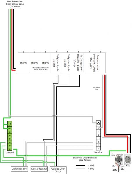
Ok guys, need some over the shoulder help. Attached is my proposed breaker wiring how does this look? In particular, is the GFI breaker wired correctly?

My current philosophy is that I want dry run before I run the heavier wire to the garage from the main panel. That is I want to test the unit before I commit to re-running and buying the heavier line.

Presently I will have a 2p 30amp breaker from the main service panel, on a 10G feed to the subpanel.

Changes I am making to the new panel:
1. 2p 30amp GFI breaker in stalled
2. Instead of a 15amp tandem breaker (as shown on page 6 of this thread) I will use two separate 1P 15amp breakers. Is this a good way to do it? HD guy said it was better practice that they did not share a neutral.


Note: I plan to wire it all up (breaker off from main panel), then let my bro in law have a look before I fire it up. Upon proof of concept and a successful test run boil with the unit, I will upgrade my feed line to #2 aluminum from the main service panel and swap in a 2pole 100 amp breaker. The 2 pole 30 amp breaker will go out to the sub panel for a 3 prong 240 outlet.


Still haven't got that hole in the kettle yet, but thought the next logical step was to get power ready before I disable my brew pot.

Thanks!

Breaker Drawing.jpg
 
oops - the wall outlet and the light circuit #1 shouldn't be sharing a ground - typo so to speak
 
looks okay to me, I don't know about the tandem breaker vs. 2 separate breakers.
Wiring the GFI is really straight forward once you get to it. There's a certain number of wires and it's pretty obvious (given their color) where everything needs to be connected.
 
Thank bruin. I am not really sure what the deal is with the tandem breaker either. The GFI curly cord is the neutral right? Then of course the terminals accept the hots for 120 each.
 
the curly wire attached to the breaker should go to the neutral bus in your panel, but the white wire that feeds out to your brewery receptacle should not come from the neutral bus. It needs to be attached to the GFCI breaker. That breaker should have a place to attach the two hot (red and black) as well as a place to attach a neutral, plus the pigtail neutral wire that is already attached to it.
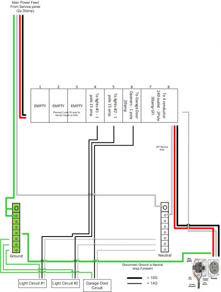
 
the curly wire attached to the breaker should go to the neutral bus in your panel, but the white wire that feeds out to your brewery receptacle should not come from the neutral bus. It needs to be attached to the GFCI breaker. That breaker should have a place to attach the two hot (red and black) as well as a place to attach a neutral, plus the pigtail neutral wire that is already attached to it.

Good point.. I forgot about that..
 
Thanks Walker - much appreciated!

So this should have it correct. Springy direct wire from GFI to neutral buss and neutral breaker screw terminal will have the line out to 4 prong 240 outlet.

Breaker Drawing.jpg
 
Back
Top