Boerderij_Kabouter
Well-Known Member
My plan is to solder a metal box onto the kettle around the element nut. I'll let you know how that goes in a couple months....

") I"ll keep an eye on it, and if it's a problem I'll go to the bigger box. I had bought a 2-gang metal box, which was too small.
I"ll keep an eye on it, and if it's a problem I'll go to the bigger box. I had bought a 2-gang metal box, which was too small.I envision that siliconed box separating after a few heat cycles/banging it around. Be careful not to tug on the cord at all. I had to redo my cords from silicone to JB weld. Silicone makes a good seal, but it's not a very good mechanical fastener.
I really like what kal did:
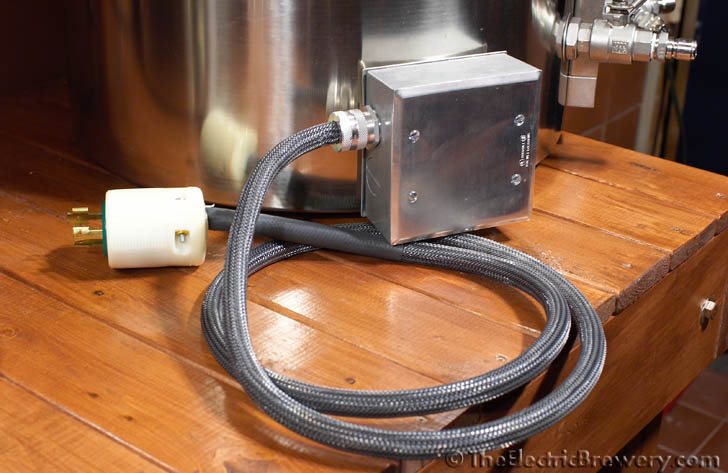
http://theelectricbrewery.com/heating-elements


![Craft A Brew - Safale S-04 Dry Yeast - Fermentis - English Ale Dry Yeast - For English and American Ales and Hard Apple Ciders - Ingredients for Home Brewing - Beer Making Supplies - [1 Pack]](https://m.media-amazon.com/images/I/41fVGNh6JfL._SL500_.jpg)


I agree...
I mounted elements in my HLT, BK, and RIMs heater the "Kal" way...
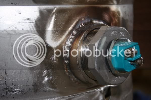
Mine are mounted into welded coupling.
Very solid, serviceable and no leaks.
No, definitely not. The 20A breaker in the box protects the 12awg wire going from the panel to the outlet. The small fuse will protect the smaller wire and PID.
I used 18awg and it was more than heavy enough.
-Joe
Got pics of that, Ed?
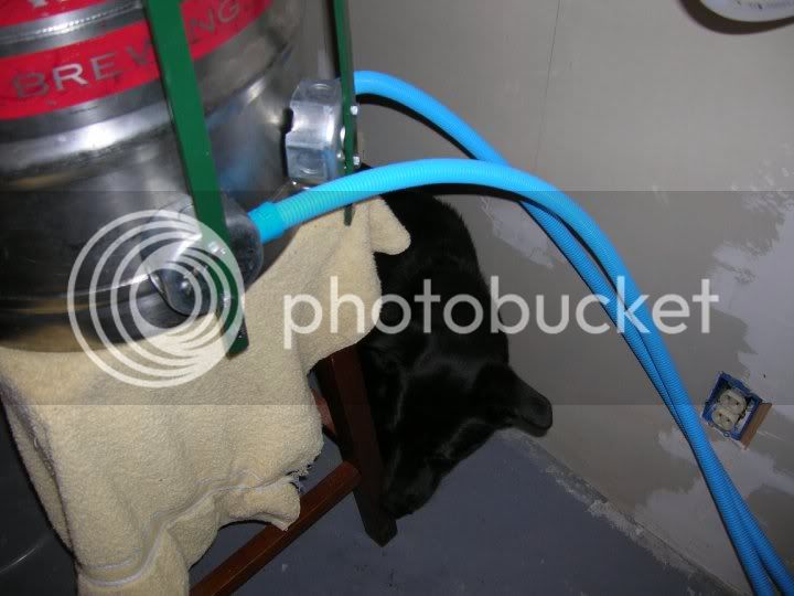
I'm just about at that that stage of my build, so I'm very interested in element mounting methods...
Thanks
Erik
Exactly, because if there were a draw on the circuit greater than the fuse, then the fuse would blow.So if there was anything more than 10a coming to that fuse holder, the breaker would trip before something bad would happen to the fuse holder. But I guess the rating of the fuse holder doesn't really matter, as long as your FUSE is less that 10a (which it will be, of course).
I did not document the process of creating the box or the technique of using the washers and o-ring... Kal did an excellent job of documenting that on his website here:
http://theelectricbrewery.com/heating-elements
Like I said, the only difference is I used a welded coupling. In fact, I used a 2" coupling and a 2"x1" bushing so there is a large flat surface for the washers / box to sit against. Here is a picture of the coupling, bushing and the element (without the box) to give you an idea of the size:
I'm delighted that you have a GFCI in place. It truly is a life saver.... The minute I switched the element's power I heard CLICK as the GFCI blew. Guess who forgot to screw the power leads onto the heating element? ...
Wet test #2 in progress. I'm very glad I'm anal about safety features because I would certainly fry myself otherwise. This time I put the heatstick back together, put it in the water and turned everything on. The minute I switched the element's power I heard CLICK as the GFCI blew. Guess who forgot to screw the power leads onto the heating element? :/
But it's been running an hour now and all seems well. I'm running at 70% power and maintaining a decent boil. I'm going to let it go a little longer, shut 'er down and check for leaks in the morning.
It's so sick to just push buttons and have it work. It's like I'm brewing in the future
-Joe

Oh... and nice work testing out the safety features before you really need them
I'm pretty sure he needed those safety features that time! Ed - do you happen to have any pics of the box actually attached to the keg? I'm also planning on welding a coupling to the keg (and using the same box as Kal does). So I would love to see the end solution so that I can get a complete idea of what I need to doI did not document the process of creating the box or the technique of using the washers and o-ring... Kal did an excellent job of documenting that on his website here:
http://theelectricbrewery.com/heating-elements
Like I said, the only difference is I used a welded coupling. In fact, I used a 2" coupling and a 2"x1" bushing so there is a large flat surface for the washers / box to sit against. Here is a picture of the coupling, bushing and the element (without the box) to give you an idea of the size:
If you're using keggles, welding can often be easier since the walls are nice and thick and easy to weld with.Thanks, Ed. I've looked at Kal's website quite a bit, and like what he did mostly. I was thinking of welding or soldering the locknut right onto the kettle wall, then securing the electrical box with gasket to that. Like you said, a nice flat surface for a good seal and strength.
If you're using keggles, welding can often be easier since the walls are nice and thick and easy to weld with.
In my setup I used Blichmann 18 gal wall kettles and every welder I talked to was scared to weld on them. They told me they couldn't guarantee that they wouldn't punch through the wall by mistake when welding on sometime to attach the element.
So I went with a 100% weldless solution mimicking exactly what John Blichmann did with his kettles.
Nothing wrong with a good permenant welded solution if you can do it!
Kal
Excellent! That's exactly what I'd do if I had used keggles (welded coupler followed by a waterproof 2-gang box to protect it). Grounded, safe, and will take a beating!I am using converted kegs for mine, so I am going to do what I mentioned above, but other than that, I'm going to use your method as guide.
Excellent! That's exactly what I'd do if I had used keggles (welded coupler followed by a waterproof 2-gang box to protect it). Grounded, safe, and will take a beating!
Kal
Thanks, Kal. Seems that (or similar) route is the way I'm going.
Can I PM you with questions about your build? I don't want to hijack Joe's thread...
(Sorry Joe!)
I envision that siliconed box separating after a few heat cycles/banging it around. Be careful not to tug on the cord at all. I had to redo my cords from silicone to JB weld. Silicone makes a good seal, but it's not a very good mechanical fastener.
I really like what kal did:
http://theelectricbrewery.com/heating-elements