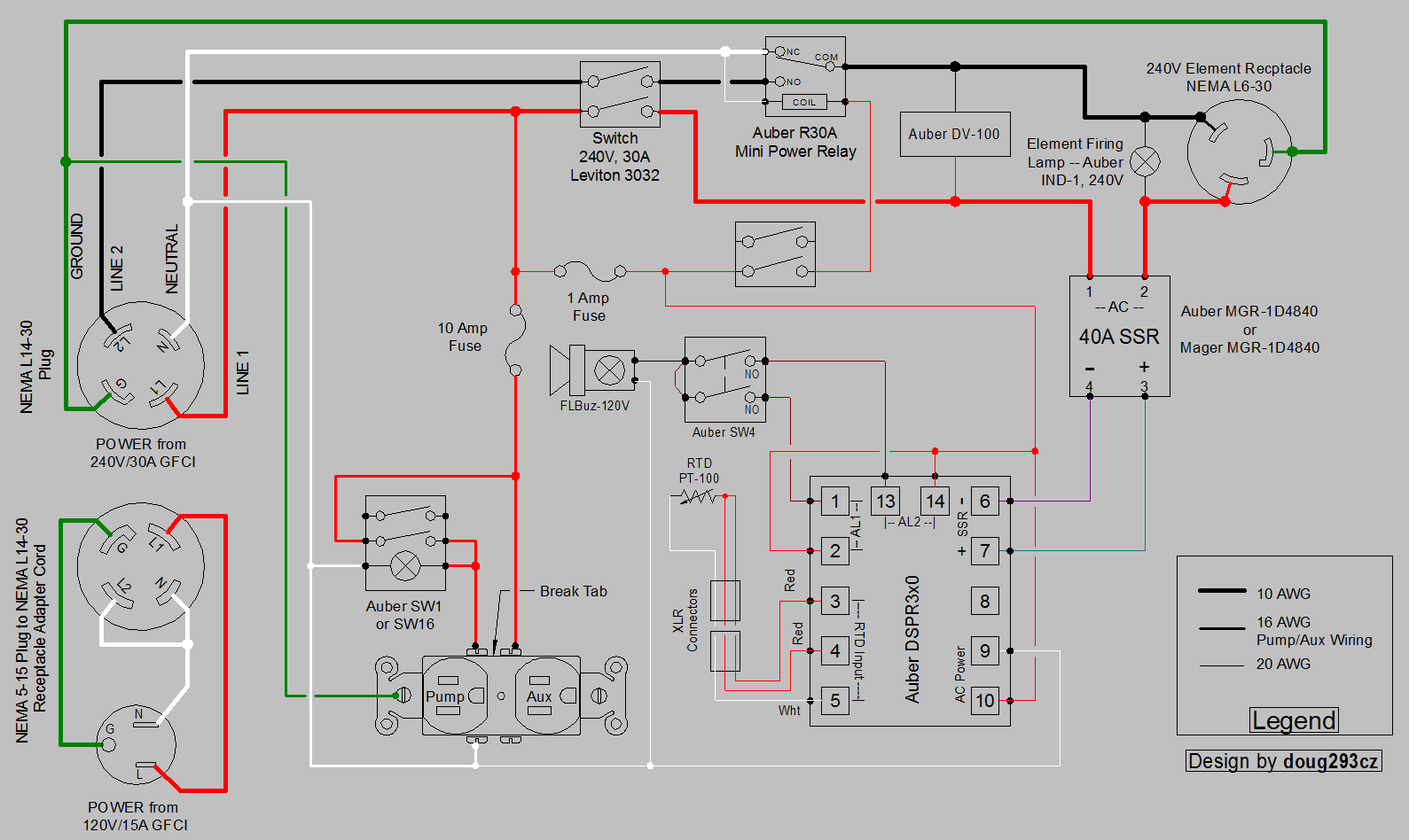
Ebiab schematic

Homebrew Talk - Beer, Wine, Mead, & Cider Brewing Discussion Forum

Help Support Homebrew Talk - Beer, Wine, Mead, & Cider Brewing Discussion Forum:

This site may earn a commission from merchant affiliate links, including eBay, Amazon, and others.

boomguy

Well-Known Member
Joined
Dec 7, 2012
Messages
64
Reaction score
11
Location
Vancouver
Hi Guys. I have decided to take the plunge into e brewing from propane! I have acquired some parts already and decided on this schematic to follow from doug293cz. It seems to tick the right boxes for pid and heating element, 5500 watts, i just would like some confirmation that this schematic is current and a good one to follow? I will be using a bayou 44 quart pot w strainer, 5500 w element, 240v power source, and recirc via a chugger pump.
Thanks
DSPR120 DV-100 1-Pump 1-Aux Dual Voltage Input Output.jpg
 
I like the switchable high/low power feature. This switch's function is the only one not labeled on the diagram you posted.

It should be very flexible and give good control when switching between mash and boil. Nice clean design as I would expect from doug293cz
 
Last edited:
Not to hijack, but I also intended to replicate this build, except using the DSPR320. Wondering if OP would also be using this latest version of the EZBoil controller? If so, wouldn't there need to be some small modification to the diagram? Especially if an alarm/buzzer were to be installed? They seem to be on most builds I see these days.

I can also confirm that this diagram is for a unit able to switch between 120v and 240v circuits using the relay, pretty cool really. Thanks Doug!
 
I was going to stick with the DSPR120 since this is my first build with a pid. Although an interesting feature being able to switch between two voltages, I will probably just stick with 240v.
 
I was going to stick with the DSPR120 since this is my first build with a pid. Although an interesting feature being able to switch between two voltages, I will probably just stick with 240v.
If you are sure you won't want to use the 120V (1375W) option, then you can leave out the R30A relay, and the switch that controls it. You could also substitute a DVA-120 for the DV-100 if you wanted to measure both voltage and current, instead of just voltage.

The plug adapter pigtail (lower left) is only needed if you ever want to operate from a 120V outlet.

Brew on :mug:
 
Not to hijack, but I also intended to replicate this build, except using the DSPR320. Wondering if OP would also be using this latest version of the EZBoil controller? If so, wouldn't there need to be some small modification to the diagram? Especially if an alarm/buzzer were to be installed? They seem to be on most builds I see these days.

I can also confirm that this diagram is for a unit able to switch between 120v and 240v circuits using the relay, pretty cool really. Thanks Doug!
You can drop any of the current EZBoil controllers into this design without changing anything, unless you want to add external alarms. To add alarms, you wire power to one side of the alarm relay in the EZBoil (use the red phase), and the other side of the alarm relay goes to the external alarm. The alarm also gets wired to neutral. You may want to put an alarm enable/disable switch between the EZBoil and the alarm. I can provide example wiring if needed.

Brew on :mug:

Hi Doug, you are truly a savior to this community, thank you for your generous divulgence of knowledge! I would indeed be curious to see the diagram of the alarm wiring as you have described. Could you please message them to me? I wouldn't want to mods to lock this thread if I'm causing things to veer too far off topic.
 
Hi Doug, you are truly a savior to this community, thank you for your generous divulgence of knowledge! I would indeed be curious to see the diagram of the alarm wiring as you have described. Could you please message them to me? I wouldn't want to mods to lock this thread if I'm causing things to veer too far off topic.
Not to worry, your question is not off topic.

Here's an updated version of the design in the first post that uses a any of the DSPR3x0 EZBoils, and has the two alarm relays wired to a single external alarm with an alarm enable/disable:

DSPR3x0 DV-100 1-Pump 1-Aux Dual Voltage Input Output.PNG


Brew on :mug:
 
So I recieved all my parts and started laying out and cutting up the box,
20190803_214912_HDR~2.jpg
a little paint and everything fit quite well.
20190808_204357_HDR~2.jpg
20190808_204437_HDR~2.jpg
I found a similar schematic from Doug293cz that I followed and added an Estop and a volt/ammeter as well.
DSPR120 1-Pump 1-Aux Dual Voltage Input contactor.PNG
If all goes well I should have my panel done tonight and I can see how my wiring turned out.
20190826_232150_HDR~2.jpg 20190826_232224_HDR~2.jpg
 
Here is a schematic with the mods I mentioned from doug293cz. 1567575100541.jpg
I am just working on my panel now and my electrician buddy is stopping by to give it a stamp of approval.
Edited to attach correct schematic
 
Last edited:
Here is a schematic with the mods I mentioned from doug293cz. View attachment 642838
I am just working on my panel now and my electrician buddy is stopping by to give it a stamp of approval.
Edited to attach correct schematic

I don't think the e-stop switch is wired correctly. It should be wired in series with your key switch and this shows it wired in parallel with the key switch.

Also, the e-stop switch is shown with a 1K resistor, which you do not want in the circuit when the e-stop is wired in series with the key switch.

I think there were some earlier versions of the e-stop being used to trip the GFCI to shut down the panel, which required a resistor to simulate a ground fault.
That is not the case here.
 
Last edited:
Interesting about the earlier versions observation
I think there were some earlier versions of the e-stop being used to trip the GFCI to shut down the panel, which required a resistor to simulate a ground fault.
6003713a170da0eadf6dadf0d4337bd5-1.jpg
I grabbed the idea from a PJ schematic and thought it made sence but as always there are many ways to create and improve on circuits... especially here.
 
The ‘controlled current short to ground’ is basically a GFCI “Test” switch. P-J was very fond of using this as an e-stop. I prefer the switch in series with the main power switch, but this normally requires a main power contractor in addition to the element enable contractor.

Brew on :mug:
 
Thanks for your input Doug! I understand why a series e stop makes more dance now.
but this normally requires a main power contractor in addition to the element enable contractor.
Unfortunately since its built now using PJs way I guess I will stick with it. 20190902_140445_HDR.jpg
I managed to get the panel finished up and my electrician stopped by and gave it a stamp of approval... plus enjoyed a beer from the kegerator! The gfci test switch works well and now to plug in the box in the next 15 minutes! Fingers crossed!
 
Hey Guys.... so with hat in hand I come looking for solutions. I tried getting my new ebiab up and running but am running into issues. The GFCI keeps tripping when I power up. I have checked all the connections for tightness and signal path but am finding nothing wrong.... but there is. Here is a recap of the schematic and internal pics of the box.
1567575100541_resized.jpg20190808_204357_HDR~2_resized.jpg 20190826_232224_HDR~2_resized.jpg20190826_232150_HDR~2_resized.jpg
At this time my electrician friend has looked at the subpanel where I wired the gfci spa panel into and the plug coming from the spa panel. All looked good to him. I have traced both hot lines, neutral(white) and ground through to the controller and none are crossed.
When I turn on the controller the gfci trips. If I remove white from the 3 leds and converter and remove the 1 amp fuse I can power on and recieve 120v at aux household plug, confirmed with volt meter and test light, ground good. The estop works correctly too. This is where it gets a little weird. Both the pump (middle) led and element power (bottom) led are illuminated, no neutral connected. Turn pump switch on leds turn off and 123v at pump plug, off is 118v. Turn on the element switch(bottom) leds illuminate but pulse.
I have tried to figure this out on my own but need some fresh thoughts on it. Long and the short of it is I miss brewing and my old rig right now and hope there is something simple I am missing. Thanks in advance.
 
It sounds like a wiring error to me, which could be almost anywhere.
Review your work. You may have misidentified a terminal on one of the devices, which led to the wiring error.

What is the "converter"? you removed the white neutral wire from?
 
Thanks very much for the reply,
What is the "converter"? you removed the white neutral wire from?
Spell check changed it... I meant contactor. I pulled it and the neutral to the leds trying to figure out where the short was. I am going to try individual neutrals to the bus bar instead of daisy chaining. Maybe that will get be a bit farther
 
Thanks very much for the reply,
Spell check changed it... I meant contactor. I pulled it and the neutral to the leds trying to figure out where the short was. I am going to try individual neutrals to the bus bar instead of daisy chaining. Maybe that will get be a bit farther
Did you accidentally ground the neutral bus bar somehow? That would be consistent with your symptoms.

Brew on :mug:
 
Did you accidentally ground the neutral bus bar somehow? That would be consistent with your symptoms.
I do have the ground going to one of the bus terminals so I can split it out to household outlet (pump/aux) but I will double check the bus bar itself isn't grounded.
 
Thanks very much for the reply,
Spell check changed it... I meant contactor. . I am going to try individual neutrals to the bus bar instead of daisy chaining. Maybe that will get be a bit farther

Never let your spell checker do your composing for you.

Isolating a fault like this requires a systematic approach. Disconnecting individual neutrals or hots from devices may allow you to drill down to the root cause (or causes).
 
So I got home from work and eliminated the PJ ground shunt, wired all neutrals directly to the bus bar instead of daisy chaining, checked bus bar for ground and checked that none of the strips were shorting to ground or neutral. Re checked my 240v outlet and plug that nothing was touching something it shouldn't. Plugged it in, turned the key switch and pop goes the gfci breaker. Pulled out the 1 amp fuse and it would turn on, power to the 120v aux plug, turn on the pump switch and the gfci would trip. Now I have checked the gfci test button and it tests properly but I am including a pic because something must be wrong. I remember reading something from PJ about wiring the spa panel but can't find it now, maybe there is something relevant.
20190916_223312_HDR.jpg
 
It sounds like the GFCI is tripping anytime current flows through any device in your panel. There may be a problem with the panel, but as a sanity check, I would want to rule out a problem with the GFCI.
You could do this by unplugging your panel, and connecting a simple test load like a pair of light bulbs into the NEMA L14-30 receptacle that your panel would normally plug into.

If the GFCI works OK with a test load (the light bulbs) then that rules out a defective GFCI.

Assuming two regular 120 volt light bulbs, they would connect L1 to N for one bulb and L2 to N for the second bulb.

If the breaker trips with one or both bulbs, the GFCI breaker has a problem.
 
Its very obvious what is wrong. The neutral wire on the load side is bypassing the gfci breaker and going to your buss. That wire should terminate on the lug on the breaker ONLY.

In the picture or is not clear to me where the neutral lug is located but it has to be there. The gfci MUST be able to measure neutral current to be able to sense imbalances.
 
Last edited:
Bobby's got it. If your breaker has no designated load-side neutral lug, as it appears from the photo, then your GFCI is designed for a straight 240 volt load w/o a neutral and is not what you want.

A 2 pole GFCI intended for use with a load-side neutral will have another lug on the load side for neutral.

My guess is your brew panel could be fine, but you will need to get the correct GFCI type for continued panel start-up testing.
 
Last edited:
In the picture or is not clear to me where the neutral lug is located but it has to be there.
Exactly what I thought! But I couldn't find it anywhere....so after miss interpreting a spa panel diagram and having my electrician check my work, I took the breaker out of its housing and at the bottom tucked up almost behind it was the lug! A quick rewire and .... Drum roll please...20190917_071230_HDR~2.jpg
It fired right up! One of the leds and the volt/amp meter aren't hooked up but I had to get to work. So the old question of Who has two thumbs , turned 50, super excited and eternally grateful to Bobby_M for spotting what my electrician missed and everyone else on this threads help! 1560921095465.jpgthis guy!
 
Last edited:
Bobby's got it. If your breaker has no designated load-side neutral lug, as it appears from the photo, then your GFCI is designed for a straight 240 volt load w/o a neutral and is not what you want.

A 2 pole GFCI intended for use with a load-side neutral will have another lug on the load side for neutral.

My guess is your brew panel could be fine, but you will need to get the correct GFCI type for continued panel start-up testing.
But wouldn't a 240V only GFCI not have a neutral pig tail?

Brew on :mug:
 
But wouldn't a 240V only GFCI not have a neutral pig tail?

Brew on :mug:

I will admit, its possible. I was reviewing a couple of electrical forums that claimed that there are 240 volt-only GFCI breakers out there with a neutral pigtail but no load side connection.
I can not verify that from personal experience.
Glad Boomguy found the missing lug and solved the mystery.
 
Last edited:
Back
Top