• Please visit and share your knowledge at our sister communities:
  • If you have not, please join our official Homebrewing Facebook Group!

    Homebrewing Facebook Group

ebay aquarium temp controller build

Homebrew Talk

Help Support Homebrew Talk:

This site may earn a commission from merchant affiliate links, including eBay, Amazon, and others.
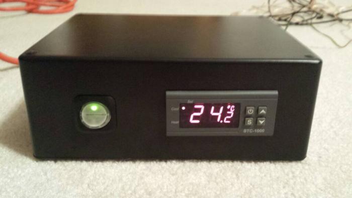
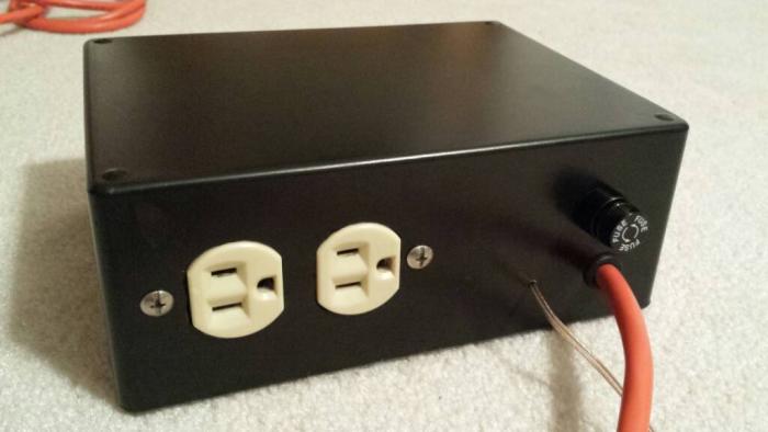
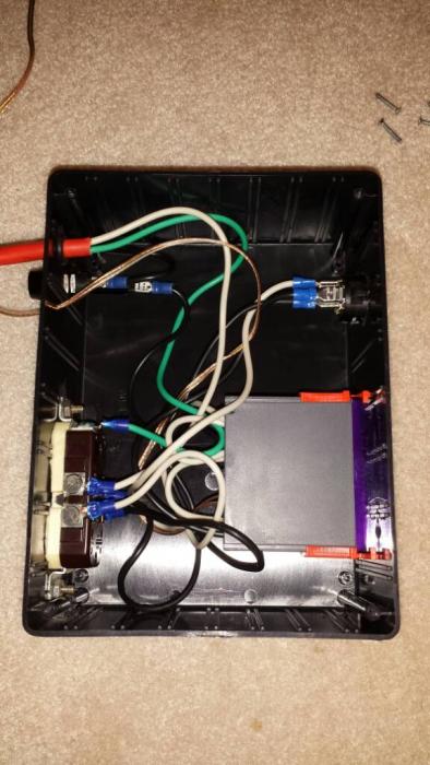
Here's mine. Inspired by this thread. I used a project box from Radio Shack and an extension cord from Wal-Mart for all the wiring. The outlets I had laying around. I also snagged the awesome power switch and fuse holder from Radio Shack.


Sent from my Android using the HomebrewTalk mobile app.
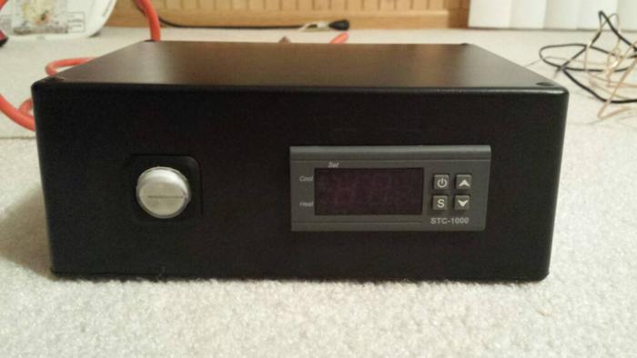
1393954330277.jpg


1393954346299.jpg


1393954361728.jpg


1393954374177.jpg


1393954396497.jpg
 
Ok just got finished with my controller and plugged it in...I get an EE on the screen along with an audible alarm...screeching actually. Anybody else have this problem? ideas? I am thinking i might have to adjust the settings to get it to work, but the EE is an error message.
 
ok nevermind...I was in such a rush to finish i for got to hook up the sensor! silly me! hooked it up and no sound or EE message.
 
Haha - I did the exact same thing re: not having the sensor wired when I first tested it.

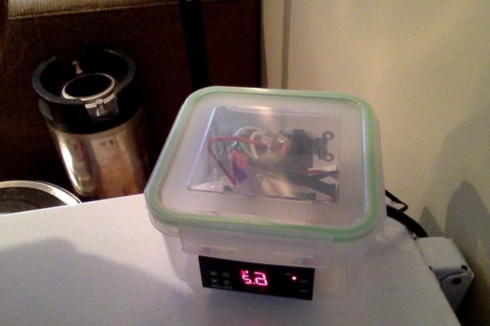
I got my temp control wired up real quick, despite a total lack of electrical knowledge. I ended up using a sturdy plastic food container (Home Hardware brand) instead of a project box, because project boxes are spendy and would have required a special trip downtown.

I like the clear look, although obviously people's opinion will differ on that. the box is going to be mounted to the side of the freezer with industrial velcro. This freezer is somewhat beat up/definitely not my "long term" freezer. When I invest in a "nice" freezer, I'm absolutely going to mount the temperature controller directly in the lid/collar.

Edit: From the angle, it's hard to tell the scale, but the temp controller and plug (no outlet cover - I cut the holes to exactly match the shape of the plugs) barely fit in the box. It's quite compact.

Photo on 2014-03-12 at 8.28 AM.jpg
 
What do you guys use to secure the power cable from coming out from the project box?


Sent from my iPhone using Home Brew
 
What do you guys use to secure the power cable from coming out from the project box?


Sent from my iPhone using Home Brew

A rubber grommet and a zip-tie on the inside.

Sent from my Android using the HomebrewTalk mobile app.
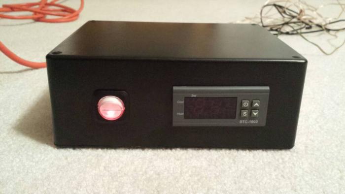
 
Just thought I would add my temp controller build to the list. I was looking for something as small as possible yet still allow for an outlet. Digging around the local big orange home supply center, I found a plastic box that measures 4x4x2. So of to work I went cramming everything inside and here are my results.

TempControllerApart.JPG


And all closed up ready to be put to use:
TempControllerTogether.JPG


I think the only change I would make is to place the controller about 1/8-3/16th of an inch lower in the box. As it is right now, the outlet pushes on the controller a bit, but too much. Ready to control the heating and cooling for my fermentation chamber year round! Time to brew up some Lager!
 
Sdgenxr. Could you post a clearer photo of the wiring diagram? Is this the new Heat & Cool, Fahrenheit model that was in development? If so, how can they be obtained?
 
raouliii: It is not an STC-1000 and it does heat and cool. I've even tested to make sure that it works as I wired it up.

TempControllerSchematic.jpg
 
raouliii: It is not an STC-1000 and it does heat and cool. I've even tested to make sure that it works as I wired it up.
....
Did you find this ready-made or did you have to special order a quantity to get Fahrenheit? I couldn't make out the wiring in your photo. There must be a jumper in there somewhere.
 
raouliii: Yes, there is a jumper in there that is as low profile as I could get. Nice catch!! The link you have is the exact one that I have.
 
raouliii: Yes, there is a jumper in there that is as low profile as I could get. Nice catch!! The link you have is the exact one that I have.
Looks like you're using two wire lamp cord. I'd recommend using a cord with a ground, attached to the receptacle. The fridge/freezer should then get a good ground from the house wiring.
 
Looks like you're using two wire lamp cord. I'd recommend using a cord with a ground, attached to the receptacle. The fridge/freezer should then get a good ground from the house wiring.

I actually just used that wiring to test the configuration. I now have it hooked directly up to the wiring on my wine fridge bypassing the stock relay and temperature control circuit. The outlet is for future heating needs and not grounded. I'll wait and see if any heating pads need a grounding wire or not.
 
Just thought I would add my temp controller build to the list. I was looking for something as small as possible yet still allow for an outlet. Digging around the local big orange home supply center, I found a plastic box that measures 4x4x2. So of to work I went cramming everything inside and here are my results.

TempControllerApart.JPG


And all closed up ready to be put to use:
TempControllerTogether.JPG


I think the only change I would make is to place the controller about 1/8-3/16th of an inch lower in the box. As it is right now, the outlet pushes on the controller a bit, but too much. Ready to control the heating and cooling for my fermentation chamber year round! Time to brew up some Lager!

I used the same size box, and put the outlet in the back. Plenty of room that way.
 
I used the same size box, and put the outlet in the back. Plenty of room that way.

I was thinking about doing that as well, but wanted to have the power cord going out the back for placement in my fridge. Good to know that you can place the outlet in the back as well.
 
Hey I am trying to convert my wine fridge into a fermentation chamber.

The problem I am having is the fridge defaults to its factory settings every time the power is turned off. I would like to bypass this feature if I could.

I have looked all through the 4000+ posts for this issue but could not find any info on this. I am presently building the dual controller with the STC-1000 to use in this project.
I will be plugging the fridge and a small heater in to the dual controller.

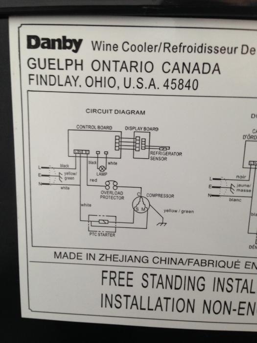
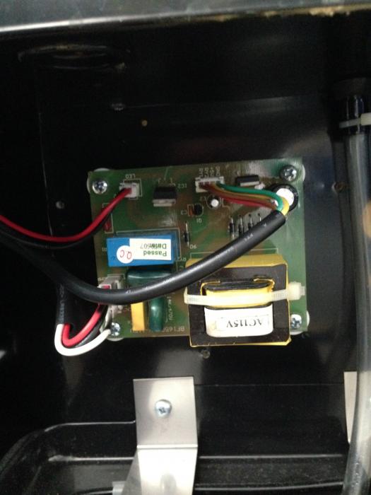
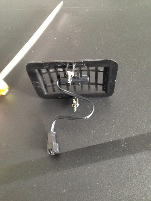
I have included a couple pics of the wiring diagram, circuit board and the temp probe.
I have tried just unplugging the temp probe but the alarm sounds and the fridge doesn't work. Also tried unplugging the connectors from the circuit board.

I can wire and build projects but my electrical knowledge is very weak. I would appreciate any help or direction to another thread.

IMG_1460.jpg


IMG_1461.jpg


IMG_1464.jpg
 
Hey I am trying to convert my wine fridge into a fermentation chamber.

The problem I am having is the fridge defaults to its factory settings every time the power is turned off. I would like to bypass this feature if I could.

I have looked all through the 4000+ posts for this issue but could not find any info on this. I am presently building the dual controller with the STC-1000 to use in this project.
I will be plugging the fridge and a small heater in to the dual controller.

I have included a couple pics of the wiring diagram, circuit board and the temp probe.
I have tried just unplugging the temp probe but the alarm sounds and the fridge doesn't work. Also tried unplugging the connectors from the circuit board.

I can wire and build projects but my electrical knowledge is very weak. I would appreciate any help or direction to another thread.

Just a guess here by looking at the provided schematic, try jumping the red and white wires in the lower left of your circuit board and see if the compressor kicks on. Trace those two wires back to the compressor to be sure they connect to it. If so, then those are the two wires that would connect to your temp controller.
 
Since the unit resets itself when it is unplugged, is it your intention to plug the fridge into an external STC1000 controller and bypass the internal controller?

If so, it should be the black and red wires on the lower left of the circuit board that need to be jumped together. The Black is HOT and the Red is the HOT to the compressor. The red wire should be disconnected from the original board and jumped to the black wire with a good solid electrical connection. It may be best to strip a couple inches of the black jacket from the black/red/white bundle to do a good job. Cut the black wire and the red wire. Strip the insulation and wire nut the two black wires with the red wire that goes to the compressor, together. Cap off the red wire that goes to the control board. All the other existing wires can be left intact to keep the existing control board happy, it just will no longer have control of the compressor. In this configuration, the fridge compressor will always run when it is plugged in, so be sure to use that external controller.

The internal controller will power up and down with the STC1000 controlled power. If you want the internal controller to not even power up then don't include the black wire to the controller in the wire nut. Of course, the internal light would no longer function at that point.
 
Back
Top