JuanMoore
Getting the banned back together
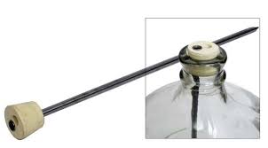
Where is the probe?
This.
And upping the delay to 10 min won't hurt anything, and might help save your compressor, especially if you have the probe just dangling.

Where is the probe?
Hanging in mid air about 1/2 way between the top and bottom of the keezer. I have a cup of water in there to put the probe in that's getting to temp but it hasn't gotten there yet.


I just noticed that Amazon has the 110V STC-1000 for less than $20 now. Free shipping on $25 orders. That's better than waiting for a package from China.
http://amzn.to/16NXgvz
Has anyone run the temperature probe through the blowoff tube and have it sitting in the wort while fermenting? Came up with the idea but not sure how well it'd work

Are you saying that the tab between the two Hot/Brass screws is broken off? What about the Neutral/Silver side? Does it trip the breaker immediately, or when the controller calls for cool or heat?....The bottom end of the outlets tab is broken. ... I plugged it in and it threw the breaker....
Has anyone run the temperature probe through the blowoff tube and have it sitting in the wort while fermenting? Came up with the idea but not sure how well it'd work
It used to be fairly common. Search thermowell. They come with a cork with 2 holes, one for the airlock and the other for the thermowell. You slide the temp probe into the thermowell.
They don't work as well as you would think. Temp swings WAY too big due to the time lag for the entire wort to change temp. If you control your temps manually, or just want to see the wort temp, it would be fine, but not with a controller. At least this was the responses I used to see.
Anyone see anything wrong with my wiring? The bottom end of the outlets tab is broken. Black are my main power wires, green are hot, cold, and ground, white are neutral. I plugged it in and it threw the breaker. Any help is much appreciated!
Are you saying that the tab between the two Hot/Brass screws is broken off? What about the Neutral/Silver side? Does it trip the breaker immediately, or when the controller calls for cool or heat?
Make sure all your connections are tight and no shorts exist between over-stripped wires.
The side of the outlet with a silver screw should be wired as neutral and the brass screw side should be wired as hot. No. If you wired this wrong you can simply put a jumper in to replace the tab. The possibly over-stripped wires would be at the controller clamps. Copper touching between two wires would create a short and lead to a tripped breaker.The tab where my heat cool wires are connected is broken and the neutral side is not. It blows the breaker immediately. I'm most definitely not an electrician so by saying shorts by over stripped wires you mean that in the wiring nut, and in the controller itself are over stripped and should only be long enough for the controller to clamp on it? I might have over stripped and need to trim them.
Edit: I just had my wife look at it. I'm at work. I dont remember ever seeing anything about brass screws and silver screws....I broke the tab on the silver side...is my outlet toast? I mean its no big deal to buy another one at $1.50.
Anyone see anything wrong with my wiring? The bottom end of the outlets tab is broken. Black are my main power wires, green are hot, cold, and ground, white are neutral. I plugged it in and it threw the breaker. Any help is much appreciated!
You have the hot side and neutral sides of the outlet reversed. As mentioned, the silver screws on the same side as the ground screw are for the neutral wires, and the brass screws on the other side are for the hot wires. You'll need to break the tab between the brass screws, and make a jumper to connect the silver screws where you broke the tab off. Or just use another outlet that doesn't have the neutral tab broken.
The side of the outlet with a silver screw should be wired as neutral and the brass screw side should be wired as hot. No. If you wired this wrong you can simply put a jumper in to replace the tab. The possibly over-stripped wires would be at the controller clamps. Copper touching between two wires would create a short and lead to a tripped breaker.
Is it a valid assumption that the other end of the power cable is pre-wired?
I agree with this post, however, the simple mistake of switching hot and neutral on the receptacle will NOT cause the circuit breaker to trip, especially if nothing is plugged into the receptacle. The OP has another problem.You have the hot side and neutral sides of the outlet reversed. As mentioned, the silver screws on the same side as the ground screw are for the neutral wires, and the brass screws on the other side are for the hot wires. You'll need to break the tab between the brass screws, and make a jumper to connect the silver screws where you broke the tab off. Or just use another outlet that doesn't have the neutral tab broken.
The simple answer is that it is standard practice and a National Electrical Code requirement associated with personal safety. Many current two prong plugs are polarized with wide and narrow blades and three prong plugs are polarized by design. This polarization exists to ensure consistent connection of hot and neutral to an appliance, which requires having receptacles wired to this standard as well. FWIW, neutral is considered the "grounded conductor" by NEC because it is grounded at the main and therefore has no electrical potential referenced to ground. Many applicances are designed with this standard in mind and applying 120VAC to the neutral of the appliance could present a danger to the user.I'm ignorant to this matter, but can you explain why this matters? I see 110v electric as two wires and a ground. Which of the two power wires goes where has never caused me any issues. In his illustration he has one side of the outlet powered all the time, the other is switched. Why does the hot/neutral matter?
I ask because as I said, I've never given it much mind, but I will if it's significant.
I'm ignorant to this matter, but can you explain why this matters? I see 110v electric as two wires and a ground. Which of the two power wires goes where has never caused me any issues. In his illustration he has one side of the outlet powered all the time, the other is switched. Why does the hot/neutral matter?
I ask because as I said, I've never given it much mind, but I will if it's significant.
I agree with this post, however, the simple mistake of switching hot and neutral on the receptacle will NOT cause the circuit breaker to trip, especially if nothing is plugged into the receptacle. The OP has another problem.
Ok, sorry to further de-rail the thread, if I'm doing so, but in an extension cord, white is hot, black is neutral then?
I agree with this post, however, the simple mistake of switching hot and neutral on the receptacle will NOT cause the circuit breaker to trip, especially if nothing is plugged into the receptacle. The OP has another problem.
The simple answer is that it is standard practice and a National Electrical Code requirement associated with personal safety. Many current two prong plugs are polarized with wide and narrow blades and three prong plugs are polarized by design. This polarization exists to ensure consistent connection of hot and neutral to an appliance, which requires having receptacles wired to this standard as well. FWIW, neutral is considered the "grounded conductor" by NEC because it is grounded at the main and therefore has no electrical potential referenced to ground. Many applicances are designed with this standard in mind and applying 120VAC to the neutral of the appliance could present a danger to the user.
Does all this matter in this application? A simple heating element?, not so much. A freezer or refrigerator?, yes.
YesSo does this mean there may be a short somewhere if it tripped the breaker right away?....
"put" WHAT "in"? The plug into an existing house receptacle?...I literally just barely put it in before the outlet popped and it tripped the breaker. I didn't have anything plugged in either......
Yes
"put" WHAT "in"? The plug into an existing house receptacle?
What do you mean by "the outlet popped"? Did you hear or see an arc/spark in/on the receptacle?
Sorry for all the questions, but troubleshooting requires details.
I can't quite make out where all the wires in your pic go, especially with the green being used for stuff other than ground. I'll try and explain how I wire these and you can trace yours out and see if it's the same.
Just to get our terminology the same:
You have 3 wires coming into the box: Black (hot), white (neutral) and green (ground).
You have 8 holes on the controller for wires. These should be numbered. In case they are not, assume 1-2 is the "Power Suppy" side, 3-4 are the temp probe, 5-6 are "Heating", and 7-8 are for "Cooling".
The black (hot) wire gets split into 3 wires (wire nut holding 4 wires, 1 in, 3 out).
They go to:
1. Controller port 1 (power supply hot)
2. Controller port 5 (heating switch hot - in)
3. Controller port 7 (cooling switch hot - in)
The white (neutral) wire gets split into 3 wires (wire nut holding 4 wires, 1 in, 3 out).
They go to:
1. Controller port 2 (power supply neutral)
2. Receptacle neutral (silver screw - for heat)
3. Receptacle neutral (silver screw - for cooling). Ignore #3 if you are using a single receptacle with jumper.
The green (ground) wire gets split into 2 wires (wire nut holding 3 wires, 1 in, 2 out).
They go to:
1. Receptacle ground (for heat)
2. Receptacle ground (for cooling). Ignore #2 if you are using a single receptacle for both.
Controller port #6:
Run a black or red wire from #6 to the hot (brass) screw of the heating receptacle.
Controller port #8:
Run a black or red wire from #8 to the hot (brass) screw of the cooling receptacle.
*** Notice that you do not ever run the black (hot) input wire directly to a receptacle. It goes to the controller (a 'switch') which turns it off/on.
Take a look at yours real close and see if that helps. Please be careful, even 120v can hurt. A lot.
Exactly where did you see an arc and what made a popping sound?No it's ok. I plugged the controller in the wall and I saw an arc and it made a popping sound. I bought a new outlet and the green (hot and cold) wires are properly wired to the brass screws with the tab broken. I trimmed the wires feeding into the controller and rewired them in. Now the controller won't turn on at all when plugged in. Did that arc fry my controller?

![Craft A Brew - Safale BE-256 Yeast - Fermentis - Belgian Ale Dry Yeast - For Belgian & Strong Ales - Ingredients for Home Brewing - Beer Making Supplies - [3 Pack]](https://m.media-amazon.com/images/I/51bcKEwQmWL._SL500_.jpg)


