I found about 75% of my parts on Amazon and the other at Auber. I need to make a parts list and see but I am pretty sure I am under $200 for just the controller. The element and Hot Pod case for it will be another $100. Also brand new 10 gallon kettle with TC fittings and new bag is under $200. So I am just around $500 for the whole eBIAB system minus the pump and hoses. To be purchased at a later date, once I get out of the dog house.
You are using an out of date browser. It may not display this or other websites correctly.
You should upgrade or use an alternative browser.
You should upgrade or use an alternative browser.
DIY 120v eBIAB Controller Help
- Thread starter enormous13
- Start date

Help Support Homebrew Talk:
This site may earn a commission from merchant affiliate
links, including eBay, Amazon, and others.
enormous13
Well-Known Member
I found about 75% of my parts on Amazon and the other at Auber. I need to make a parts list and see but I am pretty sure I am under $200 for just the controller. The element and Hot Pod case for it will be another $100. Also brand new 10 gallon kettle with TC fittings and new bag is under $200. So I am just around $500 for the whole eBIAB system minus the pump and hoses. To be purchased at a later date, once I get out of the dog house.
Yeah, I'm thinking I'll be just under $200 on the controller for the way I want it. That's not bad for a whole system cost either, I mean you literally saved hundreds by DIY'ing instead of buying a system from a seller.
Plus if I upgrade to a HERMs BIAB system then I can just buy a bigger box and move everything over to it.
@BeardedBrews @doug293cz
So, guys, I happened to find this while looking around the Auber site - http://www.auberins.com/index.php?main_page=product_info&cPath=64_65&products_id=698 - it pretty much checks all the boxes for me, minus the cost.
On the product page, it lists as a Key Feature "Heating element on/off control", and describes it as "It also has element control switches that allow the user to monitor the temperature when heater is turned off". I may be missing something blatantly obvious here, but I don't see a physical switch for the element, just for the pump (front) and main power (rear). Does the EZboil have some sort of built in switch to turn the element on/off that I don't know about? I skimmed the manual and didn't see anything, couldn't use the Find function to search through the document though.
Also, they sell that exact box/enclosure (http://www.auberins.com/index.php?main_page=product_info&cPath=34&products_id=369), which I'd really like to use. It'll fit perfectly where I need to store it. Just tall enough for the contactor you included in the schematic as well. I'm assuming since Auber produces this, that I could pull off the DIY and fit everything in there that's on the schematic?
Thank you for all this help, guys.
I don't think you can assume everything on my schematic will fit in the Auber box. I recommend making a cardboard mock up of the enclosure and all of the components. Simple boxes at the max component dimensions are good enough for this. Then see if everything fits without interference, and you still have room to do the wiring.
Brew on

enormous13
Well-Known Member
I don't think you can assume everything on my schematic will fit in the Auber box. I recommend making a cardboard mock up of the enclosure and all of the components. Simple boxes at the max component dimensions are good enough for this. Then see if everything fits without interference, and you still have room to do the wiring.
Brew on
I reached out to Auber about the build, so we'll see what they say about what they used in their controller. I'll probably go ahead and order the components, lay them out like you said with the cardboard, and see how we're looking from there.
enormous13
Well-Known Member
@doug293cz @BeardedBrews Here's a few responses I got from Auber regarding the build:
Auber: "The "element on/off switch" of WS-2500 is by the internal function of the EZboil DSPR310D. It stops sending the trigger signal to the SSR, to turn off the element. It is a different approach than your attached schematic. Your approach is better (especially for 240V because it has double pole cut-off ability), but it requires more panel space for one extra switch and more internal space for contactor. For 120 V system, double pole contactor is not needed."
"The DSPR310D controller has a "start" and a "stop" key. That are the A and B keys on the old picture. When you press the stop key, it stops the element as well as the timer. You can press the start key to turn on the output. ....this is how the element is turned on and off. I think that is sufficient. But you can add a R30A if you like. "
"Unfortunately, the enclosure we used for WS-2500 cannot be used to built the design of your attached schematic. There is no extra room for that element control contactor nor the switch."
So, how would you guys feel about not having an element switch, and instead relying on the EZboil stop/start function? What're the pros/cons to having or not having a physical element switch?
Also, we're running into space issues for that smaller enclosure, so I brought up using a relay instead of the contactor like you guys brought up. The Auber rep mentions "but you can add a R30A (relay) if you like", so would that mean we could drop the contactor/relay portion of the schematic if we don't utilize an element switch?
Then, on an unrelated note, was there a site update or something? The interface here looks different on my computer and going back through the thread I cannot view the schematic that Doug posted.


$159.99 ($26.66 / Count)
3M High Flow Series System BREW120-MS, 5616001, For Brewed Coffee and Hot Tea, Valve-in-Head Design
SpaceCityProviders

$10.99 ($31.16 / Ounce)
Hornindal Kveik Yeast for Homebrewing - Mead, Cider, Wine, Beer - 10g Packet - Saccharomyces Cerevisiae - Sold by Shadowhive.com
Shadowhive


$58.16
HUIZHUGS Brewing Equipment Keg Ball Lock Faucet 30cm Reinforced Silicone Hose Secondary Fermentation Homebrew Kegging Brewing Equipment
xiangshuizhenzhanglingfengshop


$76.92 ($2,179.04 / Ounce)
Brewing accessories 1.5" Tri Clamp to Ball Lock Post Liquid Gas Homebrew Kegging Fermentation Parts Brewer Hardware SUS304 Brewing accessories(Gas Hose Barb)
chuhanhandianzishangwu

$33.99 ($17.00 / Count)
$41.99 ($21.00 / Count)
2 Pack 1 Gallon Large Fermentation Jars with 3 Airlocks and 2 SCREW Lids(100% Airtight Heavy Duty Lid w Silicone) - Wide Mouth Glass Jars w Scale Mark - Pickle Jars for Sauerkraut, Sourdough Starter
Qianfenie Direct


$22.00 ($623.23 / Ounce)
AMZLMPKNTW Ball Lock Sample Faucet 30cm Reinforced Silicone Hose Secondary Fermentation Homebrew Kegging joyful
无为中南商贸有限公司


$20.94
$29.99
The Brew Your Own Big Book of Clone Recipes: Featuring 300 Homebrew Recipes from Your Favorite Breweries
Amazon.com


$7.79 ($7.79 / Count)
Craft A Brew - LalBrew Voss™ - Kveik Ale Yeast - For Craft Lagers - Ingredients for Home Brewing - Beer Making Supplies - (1 Pack)
Craft a Brew

$53.24
1pc Hose Barb/MFL 1.5" Tri Clamp to Ball Lock Post Liquid Gas Homebrew Kegging Fermentation Parts Brewer Hardware SUS304(Liquid Hose Barb)
yunchengshiyanhuqucuichendianzishangwuyouxiangongsi


$28.98
Five Star - 6022b_ - Star San - 32 Ounce - High Foaming Sanitizer
Great Fermentations of Indiana

$53.24
1pc Hose Barb/MFL 1.5" Tri Clamp to Ball Lock Post Liquid Gas Homebrew Kegging Fermentation Parts Brewer Hardware SUS304(Gas MFL)
Guangshui Weilu You Trading Co., Ltd


![Craft A Brew - Safale S-04 Dry Yeast - Fermentis - English Ale Dry Yeast - For English and American Ales and Hard Apple Ciders - Ingredients for Home Brewing - Beer Making Supplies - [1 Pack]](https://m.media-amazon.com/images/I/41fVGNh6JfL._SL500_.jpg)
$6.95 ($17.38 / Ounce)
$7.47 ($18.68 / Ounce)
Craft A Brew - Safale S-04 Dry Yeast - Fermentis - English Ale Dry Yeast - For English and American Ales and Hard Apple Ciders - Ingredients for Home Brewing - Beer Making Supplies - [1 Pack]
Hobby Homebrew


$479.00
$559.00
EdgeStar KC1000SS Craft Brew Kegerator for 1/6 Barrel and Cornelius Kegs
Amazon.com


$1.91
$29.95
Mastering Homebrew: The Complete Guide to Brewing Delicious Beer (Beer Brewing Bible, Homebrewing Book)
Goodwill Retail Services, Inc.


$44.99
$49.95
Craft A Brew - Mead Making Kit – Reusable Make Your Own Mead Kit – Yields 1 Gallon of Mead
Craft a Brew


$719.00
$799.00
EdgeStar KC2000TWIN Full Size Dual Tap Kegerator & Draft Beer Dispenser - Black
Amazon.com

$176.97
1pc Commercial Keg Manifold 2" Tri Clamp,Ball Lock Tapping Head,Pressure Gauge/Adjustable PRV for Kegging,Fermentation Control
hanhanbaihuoxiaoshoudian

@doug293cz @BeardedBrews Here's a few responses I got from Auber regarding the build:
Auber: "The "element on/off switch" of WS-2500 is by the internal function of the EZboil DSPR310D. It stops sending the trigger signal to the SSR, to turn off the element. It is a different approach than your attached schematic. Your approach is better (especially for 240V because it has double pole cut-off ability), but it requires more panel space for one extra switch and more internal space for contactor. For 120 V system, double pole contactor is not needed."
"The DSPR310D controller has a "start" and a "stop" key. That are the A and B keys on the old picture. When you press the stop key, it stops the element as well as the timer. You can press the start key to turn on the output. ....this is how the element is turned on and off. I think that is sufficient. But you can add a R30A if you like. "
"Unfortunately, the enclosure we used for WS-2500 cannot be used to built the design of your attached schematic. There is no extra room for that element control contactor nor the switch."
So, how would you guys feel about not having an element switch, and instead relying on the EZboil stop/start function? What're the pros/cons to having or not having a physical element switch?
Also, we're running into space issues for that smaller enclosure, so I brought up using a relay instead of the contactor like you guys brought up. The Auber rep mentions "but you can add a R30A (relay) if you like", so would that mean we could drop the contactor/relay portion of the schematic if we don't utilize an element switch?
Then, on an unrelated note, was there a site update or something? The interface here looks different on my computer and going back through the thread I cannot view the schematic that Doug posted.
If the SSR fails in the Auber control box, then there will be no way to shut off the element other than unplugging the box from the power input. (SSR's usually fail in the "on" state.) I would personally not own a control panel that did not have a positive disconnect feature for all SSR's. Other people feel differently.
For a 120V only panel, you could use the R30 in place of the contactor, but then you lose the ability to upgrade to 240V in the same enclosure, since 240V requires a double pole contactor/relay, and the R30 is single pole. The R30 would still require the switch, since it is a relay.
Yes the HBT forum platform software was switched on Friday. Bugs are currently being worked out. Right now even I'm not allowed to see my own attachment (and I'm a forum moderator.)
Brew on
enormous13
Well-Known Member
If the SSR fails in the Auber control box, then there will be no way to shut off the element other than unplugging the box from the power input. (SSR's usually fail in the "on" state.) I would personally not own a control panel that did not have a positive disconnect feature for all SSR's. Other people feel differently.
For a 120V only panel, you could use the R30 in place of the contactor, but then you lose the ability to upgrade to 240V in the same enclosure, since 240V requires a double pole contactor/relay, and the R30 is single pole. The R30 would still require the switch, since it is a relay.
Yes the HBT forum platform software was switched on Friday. Bugs are currently being worked out. Right now even I'm not allowed to see my own attachment (and I'm a forum moderator.)
Brew on
It sounded to me like I’d still want an element switch, and that the stop/start feature Auber lists is kind of a pseudo-workaround. The rep was also kind of suggesting that going 120v only would make for an easier and smaller build, and meet my needs.
I’m kind of leaning towards just going 120v/20a, to keep the build small. That WS-2500 that Auber offers is what I want to replicate, but we need to add the element switch and element firing light, then maybe move the probe port to the rear and drop that power switch.
BeardedBrews
Well-Known Member
I’m kind of leaning towards just going 120v/20a, to keep the build small.
The Inkbird IPB-16 might be the simplest and most cost-effective way to get to this goal if you can live with the 15a limitation.
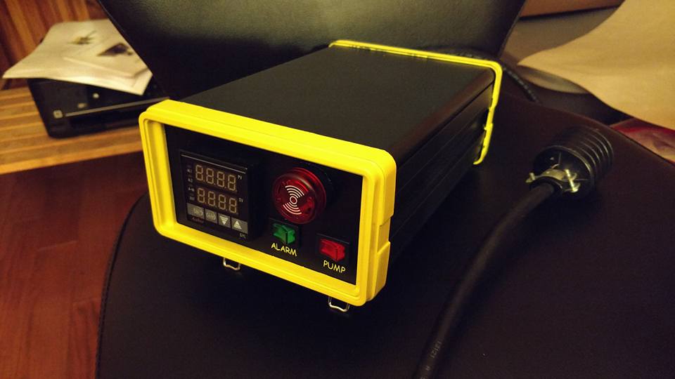
You could build something like mine.. i really like it. Has basically everything you asked for, but i dont have an element off switch..i just use the power off switch on the back. The build is in my signature.. since there arent much electronics i didnt really spend a lot of time with the wiring part but it is pretty much self explanatory if you know what your doing
enormous13
Well-Known Member
The Inkbird IPB-16 might be the simplest and most cost-effective way to get to this goal if you can live with the 15a limitation.
Definitely the most cost effective, I can't even argue that. The limitations I listed in post #1 though are what's keeping me from pulling the trigger on it:
-Lack of pump switch from factory (Bobby @ BrewHardware sells one with a switch though).
-Like you said, 15 amp limit, meaning there's absolutely zero upward mobility when factoring in anything over a 1,500 watt element and a decent pump (most running at just over 1 amp).
-No element switch.
-The probe has reports of inaccuracies.
-It is a PID based controller, but it surely isn't anything on par with the EZboil.
To save $100 on the Inkbird IPB-16 over going DIY, I just can't justify it yet. Maybe folks will continue to modify it and make it better, or they'll release a version 2.0.
enormous13
Well-Known Member
Hey Mirilis! I did see your build after some searching, and you did a wonderful job. That thing looks slick, exactly what I'm going for. How'd you get those trim pieces in yellow btw? I saw your enclosure and item list, and that's where I figured I could fit what I wanted into that box based on the needs I had listed, and all for about $200.You could build something like mine.. i really like it. Has basically everything you asked for, but i dont have an element off switch..i just use the power off switch on the back. The build is in my signature.. since there arent much electronics i didnt really spend a lot of time with the wiring part but it is pretty much self explanatory if you know what your doing
Essentially, I think I'd be just swapping out your "alarm" switch for an element switch on the face, dropping the alarm buzzer/light, and using a few components rated up to 20a, instead of 15a.
Last edited:
Alcohol wipe + yellow spray paint (they are just plastic bezels). The text was done with my wifes Cricut. I thought about building a second one for a 30A application but havent had time or funds.
Those snap in 120v recepticles are limited to 15a so you would have to use somethign different (though i think they can take it). Everything else can handle the load i think. (it has a 20a fuse it in already, and 20a rockers witch in the back, and 12gau cable from an old project)
Those snap in 120v recepticles are limited to 15a so you would have to use somethign different (though i think they can take it). Everything else can handle the load i think. (it has a 20a fuse it in already, and 20a rockers witch in the back, and 12gau cable from an old project)
enormous13
Well-Known Member
Auber does sell some 120v/20a receptacles that actually may save me some space on the face, I'd just have to convert my element's and pump's plugs to the corresponding male/female plugs. I think they'd work though. (https://www.auberinc.com/index.php?main_page=product_info&cPath=61_63&products_id=595 / https://www.auberinc.com/index.php?main_page=product_info&cPath=61_63&products_id=570)Alcohol wipe + yellow spray paint (they are just plastic bezels). The text was done with my wifes Cricut. I thought about building a second one for a 30A application but havent had time or funds.
Those snap in 120v recepticles are limited to 15a so you would have to use somethign different (though i think they can take it). Everything else can handle the load i think. (it has a 20a fuse it in already, and 20a rockers witch in the back, and 12gau cable from an old project)
I'm just waiting for the HBT software update to get some fixes so I can retrieve that schematic Doug made up earlier in this thread, and just see if he can advise me on these few changes to the 120v only build. I got a little carried away initially thinking a "120v convertible to 240v build" would be doable in this smaller enclosure.
I'll just repost it again.Auber does sell some 120v/20a receptacles that actually may save me some space on the face, I'd just have to convert my element's and pump's plugs to the corresponding male/female plugs. I think they'd work though. (https://www.auberinc.com/index.php?main_page=product_info&cPath=61_63&products_id=595 / https://www.auberinc.com/index.php?main_page=product_info&cPath=61_63&products_id=570)
I'm just waiting for the HBT software update to get some fixes so I can retrieve that schematic Doug made up earlier in this thread, and just see if he can advise me on these few changes to the 120v only build. I got a little carried away initially thinking a "120v convertible to 240v build" would be doable in this smaller enclosure.

Brew on
enormous13
Well-Known Member
Thank you, sir.
As for going just 120v/20a, am I just swapping out the contactor in the original design for a R30A relay, and wiring it similarly? Then just making sure my element receptacle and cord is rated for 20a at 120v? Any changes in the fuses or anything else I'm missing? I know I'm just bastardizing the hell out of your initial design, which I'm very sorry about, I just came to the conclusion that 120v is going to fit my needs for quite some time.
BeardedBrews
Well-Known Member
I just came to the conclusion that 120v is going to fit my needs for quite some time.
If you're permanently stepping down to 20a/120v then there are quite a few switches that would save you space and cost versus using a stand-alone contactor or relay.
https://www.amazon.com/dp/B009XP2QQ4/?tag=skimlinks_replacement-20
It would probably be best to re-draw the entire wiring diagram just so that there isn't confusion around components relative to their switches.
Also, you could switch over and use the smaller PowerCon connections if you were still planning to have dis-connectable power cords:
https://www.amazon.com/dp/B00FAROGSU/?tag=skimlinks_replacement-20
Last edited by a moderator:
enormous13
Well-Known Member
That'd be great if Doug is willing to re-draw it just for 120v application with the appropriate components.If you're permanently stepping down to 20a/120v then there are quite a few switches that would save you space and cost versus using a stand-alone contactor or relay.
https://www.amazon.com/dp/B009XP2QQ4/?tag=skimlinks_replacement-20
It would probably be best to re-draw the entire wiring diagram just so that there isn't confusion around components relative to their switches.
Also, you could switch over and use the smaller PowerCon connections if you were still planning to have dis-connectable power cords:
https://www.amazon.com/dp/B00FAROGSU/?tag=skimlinks_replacement-20
Those PowerCons seem nice, especially with the locking tab feature. Gives a little more security while providing QD cords.
Last edited by a moderator:
Thank you, sir.
As for going just 120v/20a, am I just swapping out the contactor in the original design for a R30A relay, and wiring it similarly? Then just making sure my element receptacle and cord is rated for 20a at 120v? Any changes in the fuses or anything else I'm missing? I know I'm just bastardizing the hell out of your initial design, which I'm very sorry about, I just came to the conclusion that 120v is going to fit my needs for quite some time.
Bearded is correct. You can replace the switch+relay/contactor combo with a suitably rated switch.If you're permanently stepping down to 20a/120v then there are quite a few switches that would save you space and cost versus using a stand-alone contactor or relay.
https://www.amazon.com/dp/B009XP2QQ4/?tag=skimlinks_replacement-20
It would probably be best to re-draw the entire wiring diagram just so that there isn't confusion around components relative to their switches.
Also, you could switch over and use the smaller PowerCon connections if you were still planning to have dis-connectable power cords:
https://www.amazon.com/dp/B00FAROGSU/?tag=skimlinks_replacement-20
Brew on
Last edited by a moderator:
enormous13
Well-Known Member
@doug293cz @BeardedBrews honestly, now that we've switched to 120v/20a, and dropped the contactor/relay all together, I'm beyond lost on the wiring and new components with how it would change in regards to the hot and neutral on the entire top center/top right of the schematic. I'd really need an updated version for illustration after all the changes. I'm really sorry guys.
I found a few other versions of your schematics that you've posted for folks and tried to find one similar to what I'm doing, but couldn't locate one via the search.
I found a few other versions of your schematics that you've posted for folks and tried to find one similar to what I'm doing, but couldn't locate one via the search.
Last edited:
I did notice a rather large plastic waterproof box at Lowes.com on my last trip, and quite large like 10x10x6 maybe for $30 ish.
Hope it helps.
Hope it helps.
BeardedBrews
Well-Known Member
I'd really need an updated version for illustration after all the changes. I'm really sorry guys.
I don't know what switch you would be using, but basically this. You could also replace the pump switch with the same rocker switch so that everything matched nicely.
Attachments

enormous13
Well-Known Member
Thank you so much, Bearded. I'd be fine with using two of those switches that you linked. I think Auber sells something similar, just FYI (https://www.auberinc.com/index.php?main_page=product_info&cPath=69_74&products_id=272)I don't know what switch you would be using, but basically this. You could also replace the pump switch with the same rocker switch so that everything matched nicely.
BeardedBrews
Well-Known Member
Thank you so much, Bearded. I'd be fine with using two of those switches that you linked. I think Auber sells something similar, just FYI (https://www.auberinc.com/index.php?main_page=product_info&cPath=69_74&products_id=272)
Very similar, yep. The Amazon one is stamped capable to the full 20A, even though you may not actually be needing that much through the element. I mostly liked the idea of getting 5 just in case I wanted to do some extra switching.

On that little enclosure you could have the PID on one side and probably 4 switches in a grid on the other side.


enormous13
Well-Known Member
Yeah, for some reason Auber doesn’t list that one I linked with it’s 120v amperage.Very similar, yep. The Amazon one is stamped capable to the full 20A, even though you may not actually be needing that much through the element. I mostly liked the idea of getting 5 just in case I wanted to do some extra switching.
View attachment 546650
On that little enclosure you could have the PID on one side and probably 4 switches in a grid on the other side.
View attachment 546651 View attachment 546652
Also, the Auber rep suggested single pole switches over the double poles, any reasoning there? He also said the 1amp breaker isn’t necessary, and the 10amp is oversized. I’d rather keep them in the design just for safety, if they’re still needed for 120v. How would they be mounted though? With a panel mount breaker holder?https://www.auberinc.com/index.php?main_page=product_info&cPath=7_35&products_id=593
Yeah, for some reason Auber doesn’t list that one I linked with it’s 120v amperage.
Also, the Auber rep suggested single pole switches over the double poles, any reasoning there? He also said the 1amp breaker isn’t necessary, and the 10amp is oversized. I’d rather keep them in the design just for safety, if they’re still needed for 120v. How would they be mounted though? With a panel mount breaker holder?https://www.auberinc.com/index.php?main_page=product_info&cPath=7_35&products_id=593
It's only necessary to switch hot lines, not neutrals. So with 120V circuits you only need single pole switches. Nothing wrong with using a double pole switch and switching the neutral along with the hot, or leaving one pole unused and just switching the hot line. If you use 16AWG wire for all of the wiring, you don't need to fuse at less than 10A. Max fuse size is determined by the max current the wire used can handle. You can fuse lower than that without causing problems. However, pumps are an inductive load, and thus have high inrush currents when starting up. You need to size the fuses to allow for that.
Brew on
Here is my controller.


I know it is a little bulkier than you want but it has everything Doug recommended (his design) plus I beefed up the wiring and components for 120V 20A. Here is a link to the thread.
https://www.homebrewtalk.com/forum/threads/biab-gas-mash-control-or-rims.595745/


I know it is a little bulkier than you want but it has everything Doug recommended (his design) plus I beefed up the wiring and components for 120V 20A. Here is a link to the thread.
https://www.homebrewtalk.com/forum/threads/biab-gas-mash-control-or-rims.595745/
enormous13
Well-Known Member
Oh man, that's super helpful actually. Seeing all the wiring and placement of the componenets compared to the schematic is definitely helpful for me. Thank you for posting that.Here is my controller.
View attachment 546725 View attachment 546726
I know it is a little bulkier than you want but it has everything Doug recommended (his design) plus I beefed up the wiring and components for 120V 20A. Here is a link to the thread.
https://www.homebrewtalk.com/forum/threads/biab-gas-mash-control-or-rims.595745/
enormous13
Well-Known Member
Got it regarding the DPST vs. SPST switches, thank you for that. And for the fuses, I have no doubt that you put them in there for a reason, I definitely trust your design over what might be sold as a plug-n-play controller, that's why I'd like to keep them. I was more seeing if those panel mount fuse holders were okay to use (https://www.auberinc.com/index.php?main_page=product_info&cPath=7_35&products_id=593)? Also, whether using "fast-blow" or "slow-blow" fuses is better for this application?It's only necessary to switch hot lines, not neutrals. So with 120V circuits you only need single pole switches. Nothing wrong with using a double pole switch and switching the neutral along with the hot, or leaving one pole unused and just switching the hot line. If you use 16AWG wire for all of the wiring, you don't need to fuse at less than 10A. Max fuse size is determined by the max current the wire used can handle. You can fuse lower than that without causing problems. However, pumps are an inductive load, and thus have high inrush currents when starting up. You need to size the fuses to allow for that.
Brew on
Yes, the panel mount fuse holders are fine to use. I would use fast blow fuses. If you were to fuse the pump outlet with a 2 or 3 amp fuse (since the pump is rated at 1.4A) you would use a slow blow so that the motor starting current surge wouldn't blow the fuse.Got it regarding the DPST vs. SPST switches, thank you for that. And for the fuses, I have no doubt that you put them in there for a reason, I definitely trust your design over what might be sold as a plug-n-play controller, that's why I'd like to keep them. I was more seeing if those panel mount fuse holders were okay to use (https://www.auberinc.com/index.php?main_page=product_info&cPath=7_35&products_id=593)? Also, whether using "fast-blow" or "slow-blow" fuses is better for this application?
Brew on
enormous13
Well-Known Member
Well, now that we're done with Thanksgiving weekend here, I went ahead and started ordering components for the controller build. Can't thank everyone enough who has contributed to this thread, especially @doug293cz and @BeardedBrews .
Once stuff starts arriving over the next couple weeks, I'll document some of the build and put together a spreadsheet of items used and prices, in hopes that it can help someone else in the future.
Once stuff starts arriving over the next couple weeks, I'll document some of the build and put together a spreadsheet of items used and prices, in hopes that it can help someone else in the future.
enormous13
Well-Known Member
Here's a quick breakdown on costs and an item list of everything that's going into the build. It's all on the way and the last items get here the first week of December. Until then, I put this together to see how I did.
https://imgur.com/a/QhZfb


While I definitely went over on my initial conservative price range ($200-ish), it's pretty easily explained by a few "upgrades" that cost me. I broke out those costs in the "Where to Save on Some Costs" section, and when compared to lower cost items that I could have used, this build is easily do-able for just under $200. I got it down to about $188 if I had just used some more common components.
Compare this with a few pre-made controllers that are being sold, like the:
(Hopefully the image link worked, if not, I also uploaded a .pdf. If anyone can advise me on how to drop the image directly into the post, it'd be much appreciated.)
https://imgur.com/a/QhZfb
While I definitely went over on my initial conservative price range ($200-ish), it's pretty easily explained by a few "upgrades" that cost me. I broke out those costs in the "Where to Save on Some Costs" section, and when compared to lower cost items that I could have used, this build is easily do-able for just under $200. I got it down to about $188 if I had just used some more common components.
Compare this with a few pre-made controllers that are being sold, like the:
- Auber WS-2500 ($369.95 before shipping)
- Brau Supply SV120 ($325-369 before shipping)
(Hopefully the image link worked, if not, I also uploaded a .pdf. If anyone can advise me on how to drop the image directly into the post, it'd be much appreciated.)
Attachments
Last edited:
BeardedBrews
Well-Known Member
Thought I'd drop by and include a link to help your build (possibly).
https://www.homebrewtalk.com/forum/...biab-build-stovetop-plus-120v-element.590604/
Jmrybak is using the BrauSupply unit and he included a picture of the inside to give you an idea on how they handled wiring:
https://photos.app.goo.gl/W3ktKd2kg68AM4sZ2
https://www.homebrewtalk.com/forum/...biab-build-stovetop-plus-120v-element.590604/
Jmrybak is using the BrauSupply unit and he included a picture of the inside to give you an idea on how they handled wiring:
https://photos.app.goo.gl/W3ktKd2kg68AM4sZ2

enormous13
Well-Known Member
Thanks @BeardedBrews for that, that does help a lot. That thread is great too. I was thinking about how to add a whirlpool, whether making it permanently attached or a drop in accessory.Thought I'd drop by and include a link to help your build (possibly).
https://www.homebrewtalk.com/forum/...biab-build-stovetop-plus-120v-element.590604/
Jmrybak is using the BrauSupply unit and he included a picture of the inside to give you an idea on how they handled wiring:
https://photos.app.goo.gl/W3ktKd2kg68AM4sZ2
Also, I got my powercon components that you recommended today and my power cord. I went ahead and got them wired up, super easy. I really like them so far, disconnects that are secure.
BeardedBrews
Well-Known Member
Thanks @BeardedBrews for that, that does help a lot. That thread is great too. I was thinking about how to add a whirlpool, whether making it permanently attached or a drop in accessory.
Also, I got my powercon components that you recommended today and my power cord. I went ahead and got them wired up, super easy. I really like them so far, disconnects that are secure.
Sounds like you're more on the ball than I was with my first build! Best of luck, it will be worth the work when you fire up your first batch.
enormous13
Well-Known Member
@BeardedBrews thanks brother, can't wait. Just letting the Black Friday purchases all trickle in now and getting it all ready.
enormous13
Well-Known Member
After waiting what felt like forever for a few parts, I finally had some time to mess with this project after finals were over for me and nothing else was going on around here.
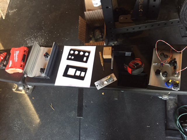
Man, cutting out those square and rectangular holes is a monumental pain in the butt. Wish I knew someone with a CNC, but there they are done. Ended up repainting the face plates since I marked them with marker for the cutouts and marred the finish on it pretty good.

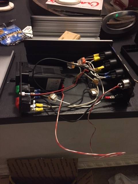
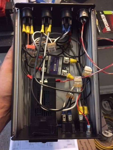
All the face and rear components in place and getting wired up. This part was actually pretty fun for me. I took it slow, checked and re-checked wiring to the schematic, tested electric flow a few times.
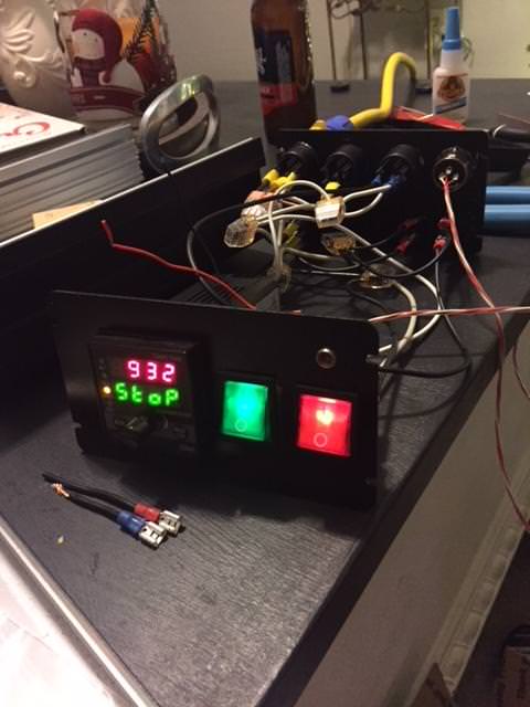
And the moment of truth, we've got lights and running electronics!
All that's left now is to mount the SSR to the enclosure, run the hot and neutral from my element switch to the SSR (just hot to SSR) and over to the element plug, and do some final testing to make sure we're not getting any unexpected power flows through switches or whatnot. Then, I'll jam it all in the box and get her closed up and ready for the first wet test with an element.
@BeardedBrews I'm loving these PowerCons. One thing to note, the grounding terminal on the backside of the plug doesn't have the room around it that the hot and neutral do, so you really have to mash a QD in there. If you're still looking to buy these, get the versions that don't have the rear fins that separate the H/N/G, or get smaller QD terminals just for the grounds.

Man, cutting out those square and rectangular holes is a monumental pain in the butt. Wish I knew someone with a CNC, but there they are done. Ended up repainting the face plates since I marked them with marker for the cutouts and marred the finish on it pretty good.
All the face and rear components in place and getting wired up. This part was actually pretty fun for me. I took it slow, checked and re-checked wiring to the schematic, tested electric flow a few times.
And the moment of truth, we've got lights and running electronics!
All that's left now is to mount the SSR to the enclosure, run the hot and neutral from my element switch to the SSR (just hot to SSR) and over to the element plug, and do some final testing to make sure we're not getting any unexpected power flows through switches or whatnot. Then, I'll jam it all in the box and get her closed up and ready for the first wet test with an element.
@BeardedBrews I'm loving these PowerCons. One thing to note, the grounding terminal on the backside of the plug doesn't have the room around it that the hot and neutral do, so you really have to mash a QD in there. If you're still looking to buy these, get the versions that don't have the rear fins that separate the H/N/G, or get smaller QD terminals just for the grounds.
enormous13
Well-Known Member
And here it is! All wired up and in the box with the face plates on, just need to slide the top cover into place. Not the prettiest job, but it all fits.
Checked the switches and outlets for voltage, and everything works so far. Switches kill power to the outlets, the element firing light is on (solid for now), etc. etc.
One item that maybe someone can answer: Checking the voltage out of the element outlet, I was getting readings around 100v, instead of 120v. Pump outlet read 120. Now, I don't have any probe going into the controller right now, so the EZboil isn't getting any temp reading, so I'm not sure how that effects the SSR or perhaps how that'd send power out to the outlet. Any ideas here? @doug293cz @BeardedBrews
Chino_Brews
Member
- Joined
- Oct 22, 2014
- Messages
- 10
- Reaction score
- 7
@enormous13, that's looking nice! Which enclosure did you end up going with?
Similar threads
- Replies
- 6
- Views
- 870
