
mattxander12
Member
- Joined
- Apr 8, 2018
- Messages
- 5
- Reaction score
- 4
This is an informational post.
A year or so ago, I purchased this mini-fridge from Costco for a fermentation chamber. It did well in keeping things in a relatively-right range for that need.
However, I found a need to turn it back into its original intention of keeping things cold. Cranked to its max settings, it never seemed to get cold enough.
I recently purchased an Inkbird Itc-308 to test this with another real data point, and then to modify my mini-fridge to get colder (if the fridge can thermally handle it). Initial readout was 45* F. Verdict is still out on if it can actually get colder or is design-limited.
Anyways, Google searches and YouTube videos gave me a basis for what I needed to do to bypass the stock thermostat, but nothing was quite exact enough to inspire confidence. Here's what I did for this model of mini-fridge, in the hope that a future person who has a similar fridge and searches for information, can find this post.
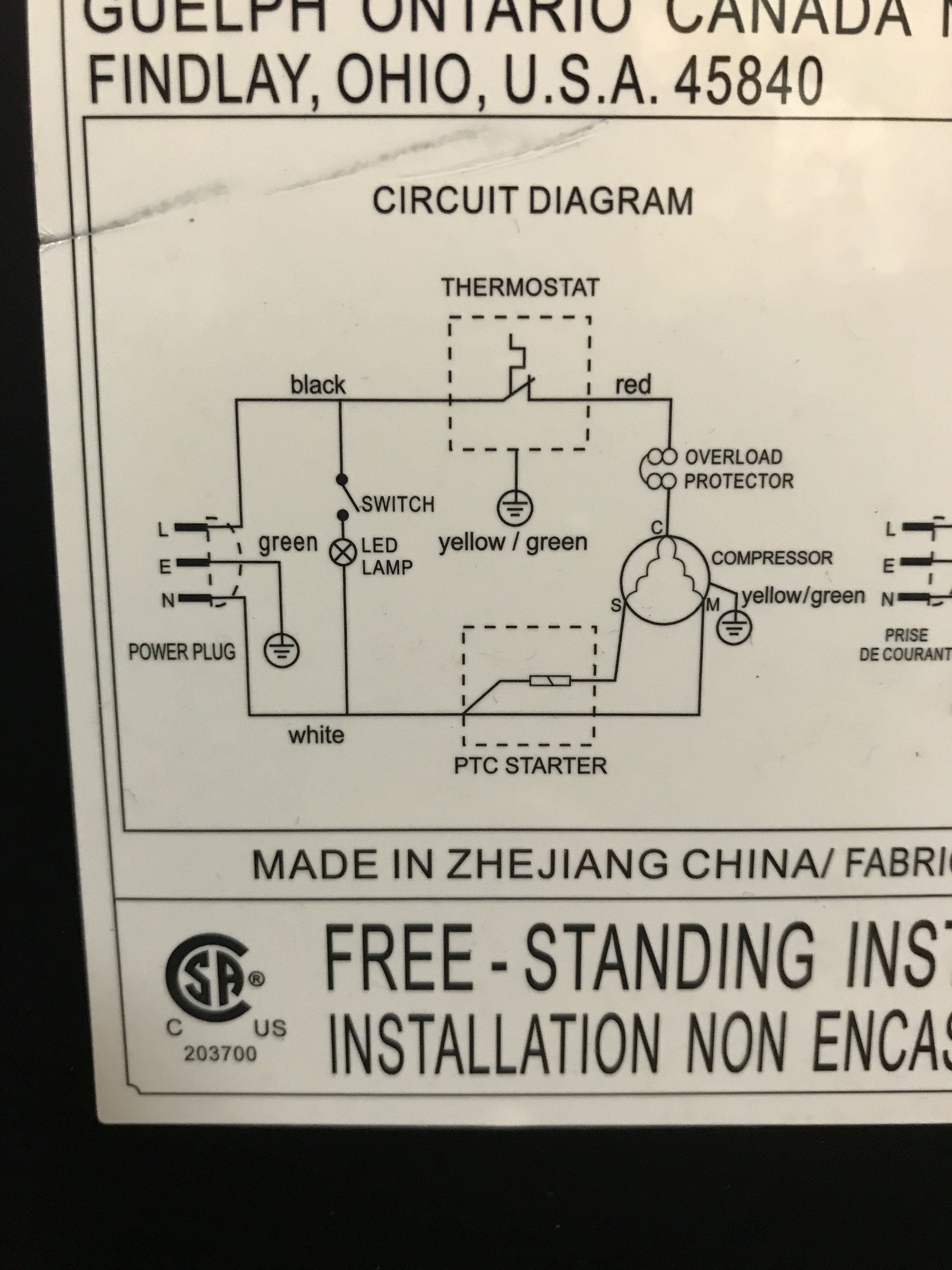
This is the wiring diagram is the 1st image.
here, its clear that the thermostat runs on a connection between Black <--> Red wires of the circuit. The fridge light runs on a Black <--> White connection with the fridge door switch completing the circuit.
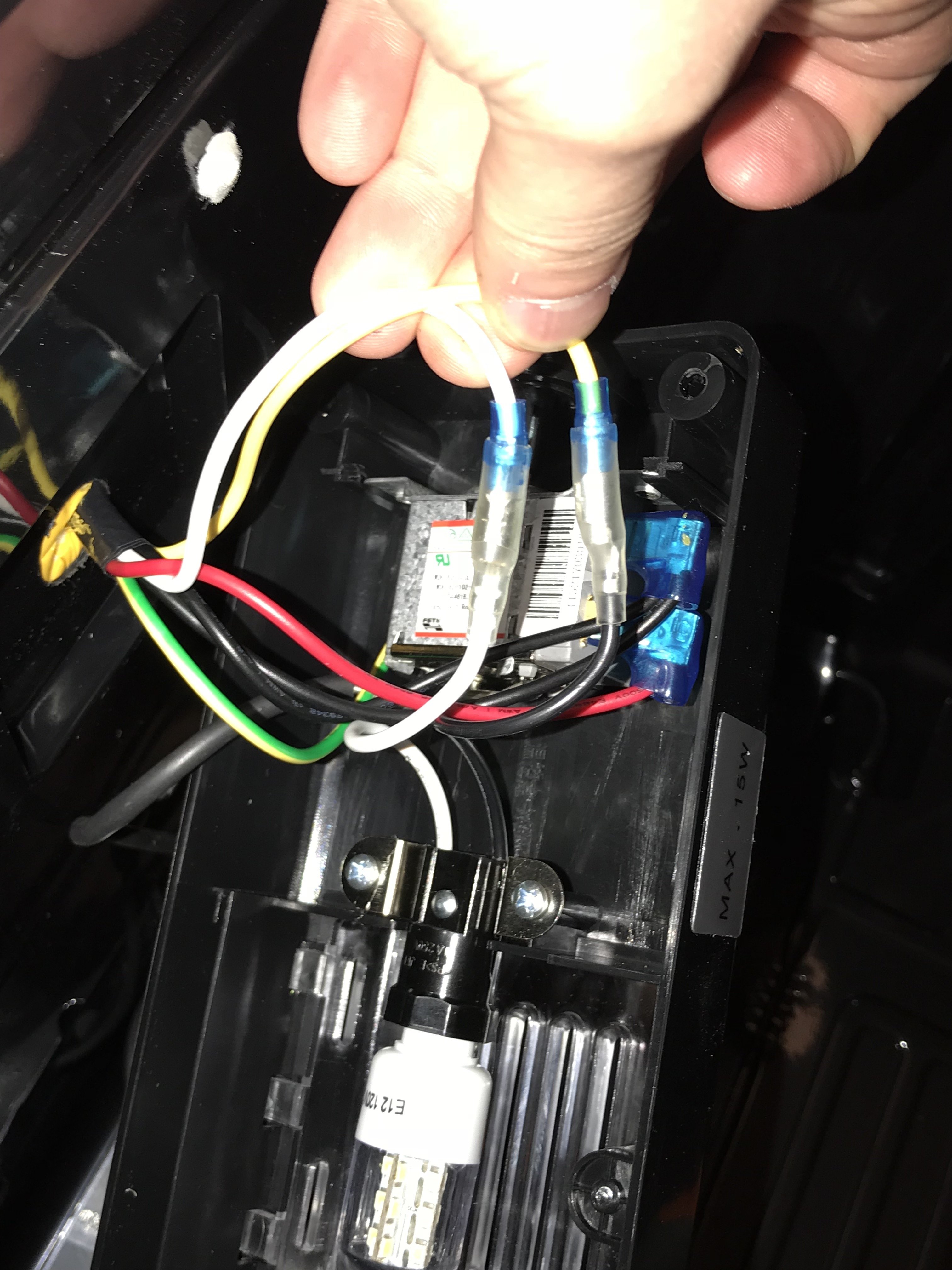
The 2nd image shows the Black wire from the diagram (2 black wires), the Red wire, and a yellow-green ground wire. Within the thermostat, when the fridge temp gets too warm, a piece of metal deforms, causing the Black <--> Red to connect and complete the circuit, kicking on the fridge condenser motor and cooling the fridge.
In the 3rd image, and on this setup, a white and yellow wire come in (and then converts into black and white) to represent the fridge lamp circuit from the schematic. Since these wires are separate from the thermostat circuit, nothing needs to be touched with this. Although, I've seen many STC-1000 threads utilizing these wires for other needs. Since I'm using an InkBird, i didn't need to touch these, and retain the "door open, light on" functionality.
Now to definitively make the fridge in an "always-on" configuration, I removed all wires from the thermostat module. I took the 2 Black wires and 1 Red wire and combined them with a wire-nut. The yellow-green wire was put into a wire-nut and taped alone, not connecting to anything since it is unneeded. I tucked the wires, and put the thermostat housing back on and it looks like factory. I tested simply by plugging it in multiple times and ensuring that I heard the compressor turn on each time it received power.
With the InkBird, I made sure to set the cooling compressor delay to the max 10 mins allowed to ensure I don't overwork the component.
And there you have it. This may seem like common-sense to many, but I wanted definitive directions before I started cutting things up, as I have 0-electrical knowledge. Hopefully this will help the next Google Searcher.
A year or so ago, I purchased this mini-fridge from Costco for a fermentation chamber. It did well in keeping things in a relatively-right range for that need.
However, I found a need to turn it back into its original intention of keeping things cold. Cranked to its max settings, it never seemed to get cold enough.
I recently purchased an Inkbird Itc-308 to test this with another real data point, and then to modify my mini-fridge to get colder (if the fridge can thermally handle it). Initial readout was 45* F. Verdict is still out on if it can actually get colder or is design-limited.
Anyways, Google searches and YouTube videos gave me a basis for what I needed to do to bypass the stock thermostat, but nothing was quite exact enough to inspire confidence. Here's what I did for this model of mini-fridge, in the hope that a future person who has a similar fridge and searches for information, can find this post.
This is the wiring diagram is the 1st image.
here, its clear that the thermostat runs on a connection between Black <--> Red wires of the circuit. The fridge light runs on a Black <--> White connection with the fridge door switch completing the circuit.
The 2nd image shows the Black wire from the diagram (2 black wires), the Red wire, and a yellow-green ground wire. Within the thermostat, when the fridge temp gets too warm, a piece of metal deforms, causing the Black <--> Red to connect and complete the circuit, kicking on the fridge condenser motor and cooling the fridge.
In the 3rd image, and on this setup, a white and yellow wire come in (and then converts into black and white) to represent the fridge lamp circuit from the schematic. Since these wires are separate from the thermostat circuit, nothing needs to be touched with this. Although, I've seen many STC-1000 threads utilizing these wires for other needs. Since I'm using an InkBird, i didn't need to touch these, and retain the "door open, light on" functionality.
Now to definitively make the fridge in an "always-on" configuration, I removed all wires from the thermostat module. I took the 2 Black wires and 1 Red wire and combined them with a wire-nut. The yellow-green wire was put into a wire-nut and taped alone, not connecting to anything since it is unneeded. I tucked the wires, and put the thermostat housing back on and it looks like factory. I tested simply by plugging it in multiple times and ensuring that I heard the compressor turn on each time it received power.
With the InkBird, I made sure to set the cooling compressor delay to the max 10 mins allowed to ensure I don't overwork the component.
And there you have it. This may seem like common-sense to many, but I wanted definitive directions before I started cutting things up, as I have 0-electrical knowledge. Hopefully this will help the next Google Searcher.
Attachments

Last edited:
