Question about this circuit....
I am going to use a Pi Zero W for a fermenter controller. I don't have a Terragady board for it, but want to bump up the 3.3v output from the Pi GPIO output to 5 or 12v for running a relay and SSR.
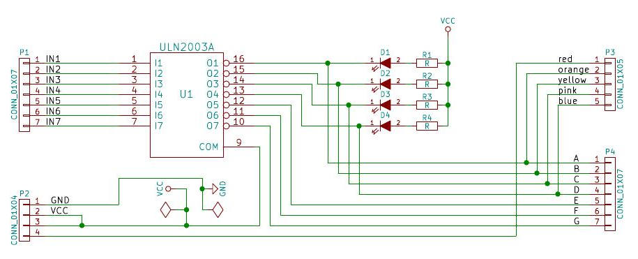
Can I just copy this circuit on a perfboard and get the same effect as the Terragady board?
I'm a bit confused on actual connections though. That top line with 5V and 12V connected together is confusing. Plus, where would I connect the SSR and relay?
But, I may need a diode, as explained at
THIS WEB PAGE.
Here is a picture of my relay, with +, - and S pins.
View attachment 624829
Here's the SSR I'll be using.
https://i.ebayimg.com/images/g/uA8AAOSwFbpaqjgR/s-l1600.jpg


![Craft A Brew - Safale S-04 Dry Yeast - Fermentis - English Ale Dry Yeast - For English and American Ales and Hard Apple Ciders - Ingredients for Home Brewing - Beer Making Supplies - [1 Pack]](https://m.media-amazon.com/images/I/41fVGNh6JfL._SL500_.jpg)