What about driving the relays direct from a Pi zero using 3v3? That still works ok without any issues?
Yes, I meant that. By breakout board I just meant the extension kind that let's you not solder directly to the Pi.

What about driving the relays direct from a Pi zero using 3v3? That still works ok without any issues?
In my humble opinion the Terragaddy boards are just an unnecessary complexity. They are really built to drive 12v relays/ssr's. If you don't need that, they are overkill. I built one and found that I could neither fully troubleshoot it or make all things (like the buzzer) work correctly. After using it for about 6 months something went wrong and some contacts stopped working and it shorted out my Pi. That is not to say that the board isn't a good product. I'm sure the quality control problems were my own fabrication faults. But for me figuring out how to troubleshoot it cost me two Raspberry Pi's. I switched to just a simple breakout board driving relays at 5v and things went much smoother.

It's nice to see that you are going with a ULN2803 to simplify your board. I questioned why more of the CBPi board makers didn't go this route a while ago.The reason the board is 12v's was to drive ssr's and pumps. Also, because most people bought crappy cheap ones from China, which in most tests I found wouldn't turn on with 5v's. If you have good SSR's, you don't have to worry about that. Also I highly doubt you fried pi's with the Terragady board setup correctly as I have had someone run 50 amps x 240 volts directly into the board and he's still alive, just short one BC337. The only way you fried a Pi is if you somehow sent more than 5v's through to pin 2, which is not good and many have done it by not setting the MP1584 up properly before connecting to the Pi.
The terragady board was a damn good board, but unfortunately it lacks all the nice new shiny features and was a pain to solder with all the individual parts. I'm in the midst of creating a new board and here is a sneak peak and yes this one supports rpi4.
View attachment 637505
Not sure this was your problem but a bunch of people fried their rpi's by not setting the voltage correctly on the mp1584.In my humble opinion the Terragaddy boards are just an unnecessary complexity. They are really built to drive 12v relays/ssr's. If you don't need that, they are overkill. I built one and found that I could neither fully troubleshoot it or make all things (like the buzzer) work correctly. After using it for about 6 months something went wrong and some contacts stopped working and it shorted out my Pi. That is not to say that the board isn't a good product. I'm sure the quality control problems were my own fabrication faults. But for me figuring out how to troubleshoot it cost me two Raspberry Pi's. I switched to just a simple breakout board driving relays at 5v and things went much smoother.
The reason the board is 12v's was to drive ssr's and pumps. Also, because most people bought crappy cheap ones from China, which in most tests I found wouldn't turn on with 5v's. If you have good SSR's, you don't have to worry about that. Also I highly doubt you fried pi's with the Terragady board setup correctly as I have had someone run 50 amps x 240 volts directly into the board and he's still alive, just short one BC337. The only way you fried a Pi is if you somehow sent more than 5v's through to pin 2, which is not good and many have done it by not setting the MP1584 up properly before connecting to the Pi.
The terragady board was a damn good board, but unfortunately it lacks all the nice new shiny features and was a pain to solder with all the individual parts. I'm in the midst of creating a new board and here is a sneak peak and yes this one supports rpi4.
View attachment 637505
I can confirm the Pi 4 is troublesome without active cooling. I just posted my findings and solution here.Have you looked into the heat issues with the Pi4? In most of the reviews I've seen testers have said that active cooling measures are really the only way to avoid throttling issues and the Pi forum is full of talk about heat and throttling on the Pi4.


![Craft A Brew - Safale S-04 Dry Yeast - Fermentis - English Ale Dry Yeast - For English and American Ales and Hard Apple Ciders - Ingredients for Home Brewing - Beer Making Supplies - [1 Pack]](https://m.media-amazon.com/images/I/41fVGNh6JfL._SL500_.jpg)


I can confirm the Pi 4 is troublesome without active cooling. I just posted my findings and solution here.
@toadyus: As long as you are creating a board, and there does seem to be ample room on the PCB, I'd suggest you make a hole and a 2-pin header for a small fan. That would be nice for everyone and almost vital for Pi 4 users.
I see the overheating as more a design snafu for the case developers. Easy enough to make it 3/8" higher and include a $0.35 fan. I have a few different USB-C power supples and was unable to figure out what they were talking about.The rpi4 seems to be a mess right now first it was the usb-c connector snafu and now issues with over heating
Maybe someone could build a CBPi board that is offset or sits at 90 degrees to the Pi board like video cards sit on a PC motherboard that would allow the use of active coolers while still being plugged directly to the GPIO pins.
If the connector is near the edge you can put one of this:
https://www.aliexpress.com/item/32596198543.html?spm=a2g0o.productlist.0.0.15fd415a4ZmrYs&algo_pvid=b7291659-a058-429e-aea1-b9f2373efb6c&algo_expid=b7291659-a058-429e-aea1-b9f2373efb6c-11&btsid=00e1cc2f-3403-4198-b6cc-06b0e3312e68&ws_ab_test=searchweb0_0,searchweb201602_2,searchweb201603_52
I agree, but Gravitysucks want the board vertical as a VGA in a motherboard. A laptop fan, that blows lateral will be a perfect choice.Just imagine the size of the case you would need if you wanted to go vertical. I think the addition of a 5v port for a case fan is the better option.
Just imagine the size of the case you would need if you wanted to go vertical. I think the addition of a 5v port for a case fan is the better option.
It isn't too big a deal to physically extend the GPIO interface header to allow something to be tucked between Pi and hat, it's likely only a matter of days before someone comes up with a "chill hat" with a skinny fan that can be topped with standard profile hats. Like the POE hat, but stackable with enough of an air gap to work.
Meanwhile...
Cheers! (yeah, it's a 3B, but the point remains. The Org done screwed the pooch this time)

Realyboard actors are the inverse of GPIO ones. Just change if they are inverted for your hardware.OK. Now I have access to Craftbeerpi3 interface but choosing the relayboard type for actors (pumps & heater) result in them being on as default : I believe they are inverted in CBPI3.
Also when I activate the heater, it turns it off. But when i do it for pump, nothing happens: it stays on.
Any advice to proceed ?
Last update:
Heating SSR is working fine but the pumps using 5v relays are always on when chosen GPIO pins are connected. Inverted box checked does not change anything. Something is still wrong in my config.
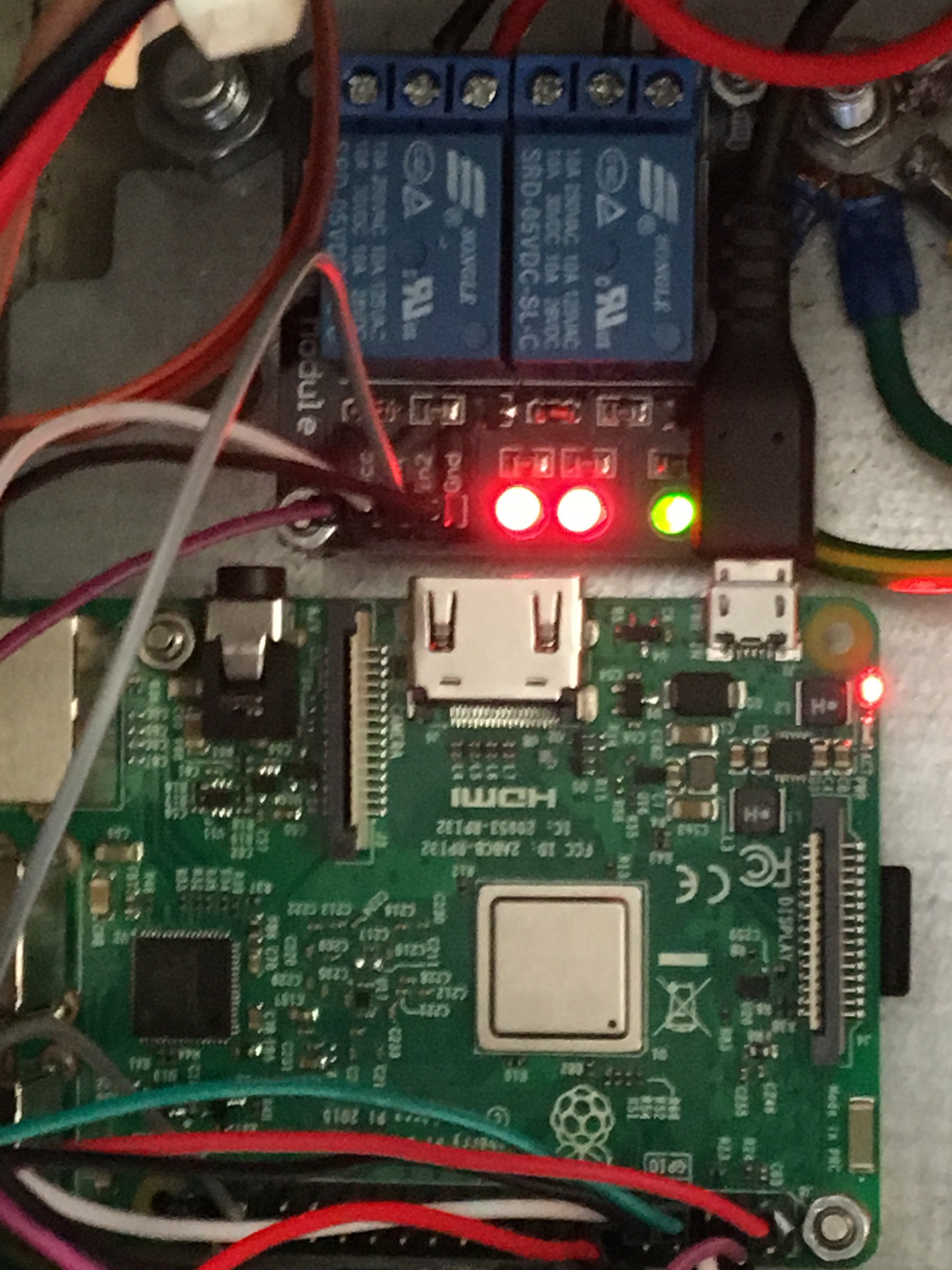
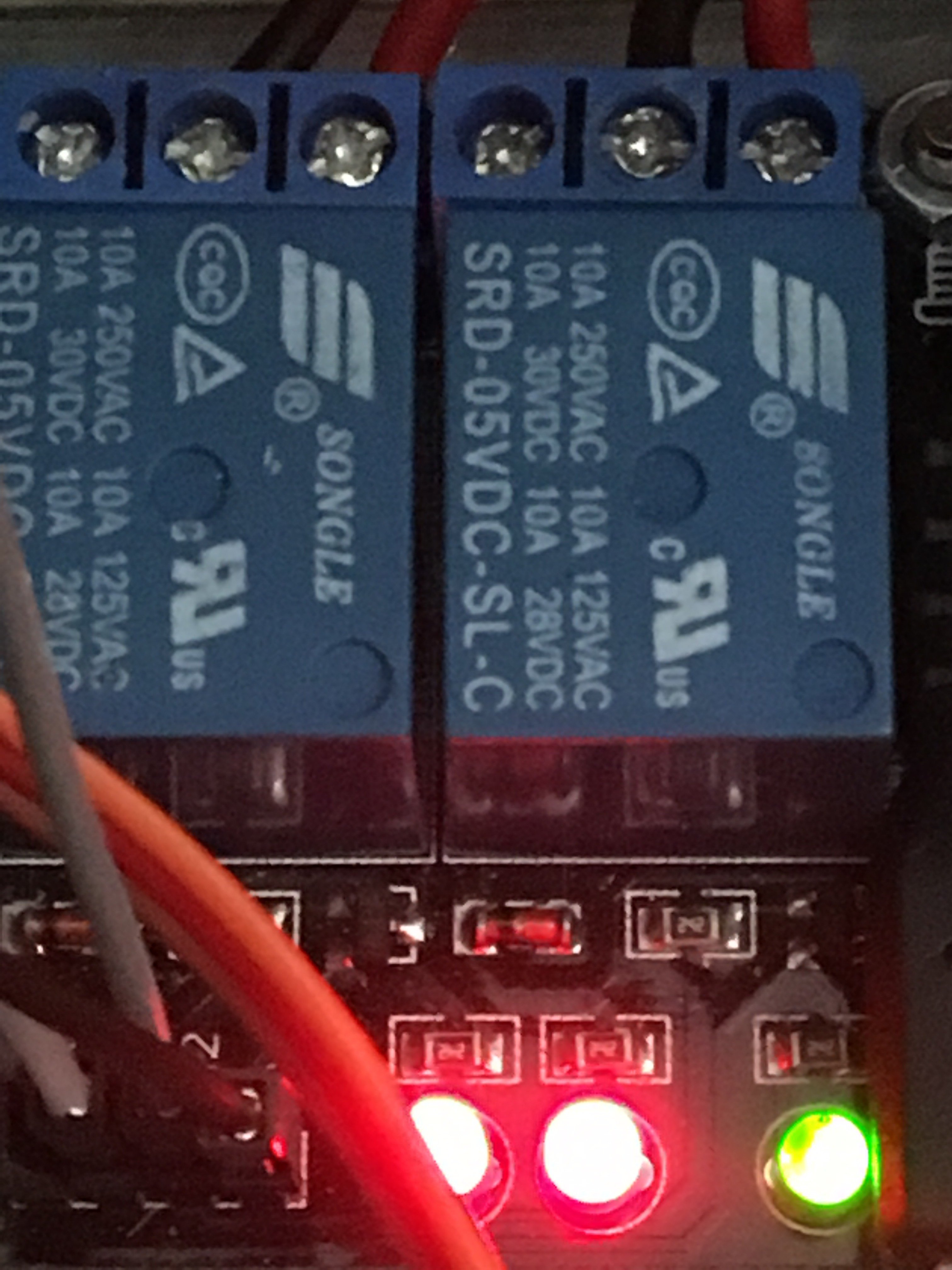
Check how you wired your pump on the relay board. I image using Com and NC (normally closed) will yield an always on state regardless of the relay board actor settings. Try using Com and NO (normally open). The OFF state will prevent voltage from Com getting tinted NO contact because voltage will be going to the NC contact (nothing connected). The ON state will send voltage from Com to NO, thus turning on your pump.
The GPIO output 3,3V , may be the 5V relay do not trigger.Last update:
the pumps using 5v relays
thanks for the support: I believe relays wiring is correct (GPIO (x2) + 5V + ground) as it was ok before and when I unplug the GPIO cable, relay led turns off.
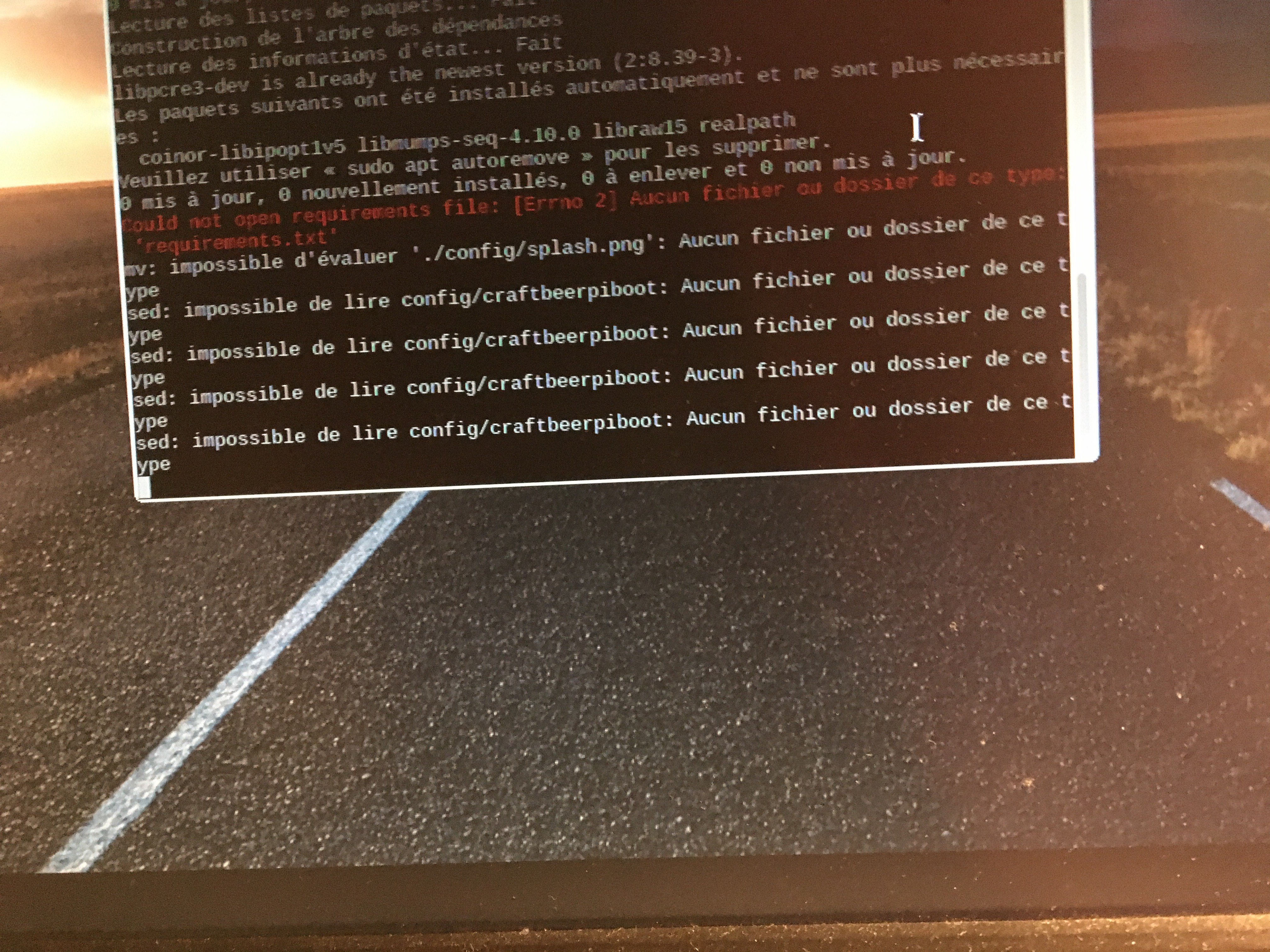
As configuration does not work correctly through CBPI hardware configuration, where can I find the file to edit & put COM and NO ?
The GPIO output 3,3V , may be the 5V relay do not trigger.


If you could post pictures of the relay board you are using and how you have it wired up it, which GPIO pins you are using, etc it might be easier to diagnose your issues.