CraftBeerPi - Raspberry Pi Software

Homebrew Talk - Beer, Wine, Mead, & Cider Brewing Discussion Forum

Help Support Homebrew Talk - Beer, Wine, Mead, & Cider Brewing Discussion Forum:

This site may earn a commission from merchant affiliate links, including eBay, Amazon, and others.
That is true, I was just trying to get in the ballpark before I put beer in it.... Even with +2 on, 0 off I'm getting 10 deg swings every hour. My graph looks like an EKG. I suppose that may not be a problem as the liquid will not change temp as fast as the ambient but figured I'd check first.


How can you have a +2 hysteresis yet have 10 degree swings? Are you talking about different probes?

This is why I won't be moving away from my BrewPi controller as I contemplate using CBPi for brewing. The PID control algorithm in that piece of software is rock solid.
 
Is the temp probe sitting in liquid or air? One trick to keep the cycles down is have the temp probe sitting in a growler (or similar container) of water.

Then the water imitates the temp swing of the beer rather than the ambient environment in the freezer.

Hope this helps! [emoji482]

The controlling probe is in air. Using a probe in liquid to contol the temp via hysteresis seems like it would be nearly impossible. Too much lag even in with small container.
 
I put two full corny kegs in my 7 cu ft freezer last night to see how it reacts vs empty. After several different settings, I settled with ON = 1 and OFF = 0.5. Whether the freezer is empty or not, this results in 2deg variation. Empty, the freezer cycles 2x per hour, with kegs it cycles once every 2 hours.

I don't think i can reduce the temp swing any more without risking short cycle when the unit is empty.
 
Will the version 3.0 have the ability to automate the GPIO pins via steps in both brewing and fermentation. Example valves?
 
If it's empty, I usually use it to make ice blocks..... I attached a graph which shows what happens when mass is added inside. Kegs were put in at 600. Liquid temp went to 67.8 and stayed.

tmp_31714-20170418_181216-498370974.jpg


tmp_31714-20170418_181719-1742397969.jpg
 
Sorry if this has been answered before, but I've only been able to find several year old answers to this.

I'm using CraftBeerPi with a hosehead controller. So far I like it but I can't figure out how to control the output of the element during boil. It's either 100% or 0%. Is there a way to reduce the output of the element to create a less vigorous boil?
 
Craftbeerpi has a patch out for manual mode for boil. I've never been able to make it work, so I use strangebrew elsinore for brewing. Craftbeerpi makes better graphs, so I like it better for fermenting control.
 
I know that they are working on putting a lot of updates and corrections in the v3 which is not released yet. If I remember correctly, they are integrating the boil control. There are a couple mods that are "use at your own risk" which implement a sort of PWM for the element.

Checkout the GitHub page for more information.
https://github.com/Manuel83/craftbeerpi
 
I'm hoping to find onewire probes that are longer than 2 inches. I want to put them in the grain bed for monitoring during mashing. Any leads?
 
I'm hoping to find onewire probes that are longer than 2 inches. I want to put them in the grain bed for monitoring during mashing. Any leads?

The sensors themselves are small plastic things about the size of a pea with three metal legs. You can solder wires of any length to these leads and connect them to your​ controller.

I like to solder mine to four-wire phone cable (one wire unused) with RJ11 plugs on the end and make a 1-wire network with phone wires, splitters and joiners.
 
I just upgraded to a 50 amp panel with the hosehead/craftbeerpi set up. However I cannot seem to get both elements firing at the same time. Any advice?
 
fwiw, swimIan was referring to the length of the probe stem, not the wire length.
And I've yet to find a ds18b20 assembled using a long stem.
Two inches more or less seems to be about all that's available...

Cheers!
 
You could use a stainless steel thermowell and stuff a sensor in the end.
 
The sensors themselves are small plastic things about the size of a pea with three metal legs. You can solder wires of any length to these leads and connect them to your​ controller.

I like to solder mine to four-wire phone cable (one wire unused) with RJ11 plugs on the end and make a 1-wire network with phone wires, splitters and joiners.

I had a lot of trouble with short-outs/breaks with phone cable and RJ11 (at least with the phone cables I was using). The copper within the cables was just too thin and was hard for a ham-handed gentleman such as myself to work with.

I switched to CAT6 and RJ45 ends and it works a LOT better. It is also easier to trace things out because there are wiring standards you can follow so you can consistent coloring all the way through.

I did black -> blue, red -> orange, and green -> green and used the "B" wiring standard throughout. The switchover made my life a lot easier.

Did you keep the twisted pair and use them as a single wire? or just use one leg of each twisted pair?

I'm planning on using CAT5 with 3-pin aviation plugs but I'm not sure abut the wire.
 
I had a lot of trouble with short-outs/breaks with phone cable and RJ11 (at least with the phone cables I was using). The copper within the cables was just too thin and was hard for a ham-handed gentleman such as myself to work with.

I switched to CAT6 and RJ45 ends and it works a LOT better. It is also easier to trace things out because there are wiring standards you can follow so you can consistent coloring all the way through.

I did black -> blue, red -> orange, and green -> green and used the "B" wiring standard throughout. The switchover made my life a lot easier.

Each to his own, I guess. RJ11 plugs and cables are less bulky, and there is a good range of splitters and joiners available because of their use in phone systems. You can also plug RJ11 plugs into RJ45 sockets, although there is a slight risk of damaging the outer spring connectors inside the socket.
 
Did you keep the twisted pair and use them as a single wire? or just use one leg of each twisted pair?

I'm planning on using CAT5 with 3-pin aviation plugs but I'm not sure abut the wire.

From the horse's mouth:
http://pdfserv.maximintegrated.com/en/an/AN148.pdf

In general, one pair (usually pair 1, in the centre) is used for data and ground, then other wires for other functions as required e.g. power etc.

In my RJ11 pinout pin 2 is data, and pin 3 is ground. That corresponds to pin 4 (blue) and 5 (white/blue) respectively in an RJ45​ connector.
 
Each to his own, I guess. RJ11 plugs and cables are less bulky, and there is a good range of splitters and joiners available because of their use in phone systems. You can also plug RJ11 plugs into RJ45 sockets, although there is a slight risk of damaging the outer spring connectors inside the socket.

Absolutely. I was just talking from my experience. I wanted to use RJ11 for all of the reasons you mentioned. It just didn't work well in my setup mainly because of the phone cables I was using. There just wasn't enough copper in the cables I had and the termination was inconsistent making the wiring complex and tracing issues difficult.
 
Below is a 3-32v triggered solid state relay module. I want to use it to switch my 2 pumps. I'd like to wire this to the ssr/relay outputs on the official craftbeerpi board. I understand how to do the AC side but I'm stuck on the control side. The official board has 2 wires for each output (ssr and com) but the module has ch 1 & 2, D.C.+ and D.C.- Your help is appreciated.

https://www.sainsmart.com/sainsmart...v-32v-5a-for-avr-dsp-arduino-mega-uno-r3.htmlView attachment ImageUploadedByHome Brew1494336027.125023.jpg
 
Hope someone can help...

I ma trying to use a 12v (or 5v, I have both) Sainsmart relay board with CraftbeerPi while using the terragady with the Pi. If I understand the terragady board, each output (GPIO) is +12 and GND. If I am trying to use the 12v relay board, should I use one output (GPIO) to power the board at VOC and GND, having it start up on High so the board is powered and then use other outputs (+12 GPIO) to trigger the relays? I want to use the realy board for my pumps since I already have it. I will use SSR for the elements and if I understand, the +12 and GND from the outputs will trigger these just fine. Just can't seem to get the realy board to work.

Thanks for any help

Dave
 
You will need to put a constant +12V to the vcc pin on the relay board, take a wire from the 12V in to power it.
Then dependant on the relay board either 12V or 0V will trigger it, so change the o/p accordingly.
 
Ok, that didn't really work for me. To be honest, much of the discussion in this thread is a bit beyond me but I am trying to learn. So...here is what I have be able to do so far...

Install CarftbeerPi on RaspPi, no problem. Hooked up 3 DS18B20 sensons to the pi using a breadboard and 4k7 resistor and got CBP to read them, no problem. Hooked up a 5v relay board to the RaspPi and was able to trigger the relays after setting them up in CBP, no problem.

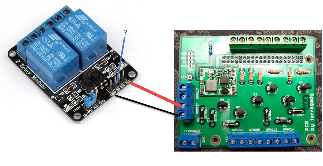
Then, read about the terragady board and thought it would be awesome to have screw in terminals and a built in resistor for the DS18B20's so bought the board. Terragady board works and no problem with the DS18B20's, CBP reads them just fine. My problem is getting a relay board to work using the terragady. Each output (GPIO) on the terragady is +12 and gnd. GPIO's on the RaspPI are 3.3v and if I understand correctly, all the grounds on the RaspPi are common so not sure why there is a ground for each output (GPIO) on the trerragady.

Also, since the outputs are 12v, I assumed that the 5v relay board would not work so I bought a 12v relay board. Can't seem to get that to work. I have powered the realy board with +12 but all my reading has suggested that the logic pin voltage on either board needs to be 5v. If that is true, then I guess I can't use the boards? I realize that I could by SSR's (Need at least one for RIMS tube element anyway) to run the pumps but that seems overkill and I already have the two relay boards.

Any thoughts/help?

Thanks

Dave
 
Your relay board will either be HI or LO activated, it should have stated in the docs.
On the setup you have to tell it whether it is active Hi or Lo.
A 12V active relay board should need 12V to activate it (or 0v dependant on the spec)

The relay should have 12V written on it.
To test:
disconnect from the pi board.
Connect 12V & 0V to the relay board.
Using a link see which activates the relay by linking 12v or 0 tvo the logic pin.
If neither work then you have a dud relay board.

On mine underneath it says Low Level Trigger so it is active low, i.e. gnd to activate.
 
Hey Dave,

Are you referring to the Terragady board having 2 outs (+12 and GND) at the screw terminals, but your relay board is looking for three inputs (V, GND, and In)?

AdhBfll.jpg
 
If you only need screw terminals these work great

http://mayhewlabs.com/product/pi-screw-terminal-breakout

I'm not familiar with that add on board, but the 5v relays should work fine wired straight to Pi header. + goes to any 5v pin, gnd goes to any ground pin and "IN1" goes to the gpio pin. Make sure to use a 2a or higher PS for your Pi if you have several 5 relays that need to be powered by the board simultaneously.

To my novice eye, it appears that that add on board passes 12 through it, so for a 12v relay you use 12v+, gnd, and then just the gpio pin from each of those gpio/gnd pairs. The pairs on the board could be used for SSRs that run off of 3v and don't need separate voltage.
 
for a 12v relay you use 12v+, gnd, and then just the gpio pin from each of those gpio/gnd pairs.

Could you draw this? In the example image above, GPIO27 is linked to the relay board through the screw terminal. The 12v and GND make total sense, but how do you wire the IN1 channel?
 
Could you draw this? In the example image above, GPIO27 is linked to the relay board through the screw terminal. The 12v and GND make total sense, but how do you wire the IN1 channel?

Ok, after looking at this board layout it looks like it may handle the gpio triggering for you. So if it does do this you need to use a stand alone relay without any control input on its board. In this case you just wire + and gnd, which looks like what you have available. Or to be simpler, just wire the 5v relays you have right to the Pi header like this photo depicts. You have to do it either the A way or the B way, cant use a board that needs a control signal with the add on board. At least it looks that way.

tmp_2709-20170605_182003-73421066.jpg


tmp_2709-20170605_180443789037175.jpg
 
Well that explains alot. I want to use the add on board because it has screw terminals for the fell probes. So i guess my best bet is just to use ssr's for the pumps as well as the elements. I just figured (hoped) I could use the relay board since I already had it. Thanks for the explanation.
 
Back
Top