• Please visit and share your knowledge at our sister communities:
  • If you have not, please join our official Homebrewing Facebook Group!

    Homebrewing Facebook Group

CraftBeerPi - Raspberry Pi Software

Homebrew Talk

Help Support Homebrew Talk:

This site may earn a commission from merchant affiliate links, including eBay, Amazon, and others.
@jangevaa
It looks like the description I added to the plugins list made it invalid (use of colon), but that has been fixed...

No.it is not fixed. Some Minutes ago i Made fresh Install and the list is empty.
 
Last edited:
Which OS are You Using? I have raspbian Stretch in latest Version.
Additional this issue is still Open in GitHub
 
Strange. Now i See it.
I activated some addins like overshoot by norn and the pid topics.
after this addon list was empty again.

But basicly i have following function questions:
1) What means the overshoot by norns logic? I tested with several values and logic is not clear
2) I read in the past was a standard overshoot. Where is it now?
3) Hysterese is clear.

For PID (PIDArduino) i need autotunePID?
 
Last edited:
Hi all, just got my craftbeerpi up and running and first batch brewed today !

I've looked all over the web and can't find any info about alarms/buzzers/notifications of any sort for Craftbeerpi (especially hop additions or steps ending)

I'm ok with any notification at all - I grabbed the IFTTT plugin but can't seem to get that to work.

Thanks for your help !
 
Hey guys.
I'm trying to set up CBPi 3 on my nanopi neo plus 2.
So far I've got it installed, and has the temperature sensors working with the GPIO4 pin.
However, I'm having trouble with the relays.
I can turn the GPIO pins on/off with the "wiringpi" utility (f.ex: gpio write 2 1) to turn gpio2 on.
But somehow I cant get CBPi to do the same.
Isn't it using the wiringpi utility?
It looks like the actors included with CBPi3 actually use RPi.GPIO. You can easily write a plugin that provides actors using wiringpi though or uses the nanopi port of RPi.GPIO
 
I managed to get it to work with the app that uses system commands instead.
But thanks for your reply :)
 
Hoping someone here can help me out. I do BIAB using CBPi 3 and have been having problems with my mash & boil processes. My mash is bad at maintaining temps and my boil is always way too strong. I did the PID Autotune process with my heater set on PID Simple and used those settings for PID Boil. However, running these on my actual brew day is not working the way it should. Once I get to the actual boil step, my boil is way overpowered (5500W element) and my boil is either overpowered or I have to manually sit there and switch it on and off. I tried changing the boil threshold but it stays at 100% regardless. Does anyone have ideas on settings to use or different plug-ins to try?
 
Hoping someone here can help me out. I do BIAB using CBPi 3 and have been having problems with my mash & boil processes. My mash is bad at maintaining temps and my boil is always way too strong. I did the PID Autotune process with my heater set on PID Simple and used those settings for PID Boil. However, running these on my actual brew day is not working the way it should. Once I get to the actual boil step, my boil is way overpowered (5500W element) and my boil is either overpowered or I have to manually sit there and switch it on and off. I tried changing the boil threshold but it stays at 100% regardless. Does anyone have ideas on settings to use or different plug-ins to try?
I brewed for the first time last night and had the exact same problem, also biab, the mash temp kept overshooting by 2-3 degrees, and I boiled off 2 gallons instead of a typical 1 gallon.
 
What would I set the logic to to set the element manually?

Should I re run pid auto tune?
I think it's PWMSimple or something like that.
I tried a different boil logic the last time I brewed and was really happy with it. IllIfire up my controller and let you know what I used.

I've also noticed that every time iveI run PID Auto tune I've come up with pretty different results.
 
So I was doing some more reading, and it looks like PWM logic is probably best for my boil. A lot of people recommended SimpleBoilLogic plugin.

One thing I noticed though is that on the website, it says that using a relay boards means that you can't used PID logic.. and I use a relay board to control my two SSRs for the heating element. Does this mean that I can't use PIDBoil at all for my mash? What should I use instead?
 
@tzacher Not entirely accurate statement. Don't use PWM with a relay board. It's possible to use PID without using PWM necessarily (not common on "hot side", but brewpi logic is a common example of this...).

That being said, why are you using a relay board to control SSRs? At most you should use a transistor to amplify the RPi GPIO, but oftentimes SSRs can be controlled directly from RPi pins.
 
@jangevaa honestly just doing what my friend that had already built a CBPi with a similar setup told me to do. It's a 2 channel relay board that I use to control the 2 SSRs for my element. One pin from the pi controls it on and off. Can I use two pins to control the same heater to go on and off?

Sorry for the ignorance, I really know very little about electronics/raspberry pi
 
@tzacher It's cool.

Do you use 2 SSRs for one element?

Try connecting the SSRs directly to your pi (assuming the control signal for them is 3-32VDC, they will probably work fine).

Those relay modules are often used to control things like pumps, lights, etc. Not useless by a long shot, but shouldn't be used for your element control circuit for sure.
 
@jangevaa I do. It's a 5500W element and the plug it's coming from is a 4 pronged dryer cord, so one hot line goes to each SSR, I believe. Then those run to a 3-prong plug.
 
@jangevaa I do. It's a 5500W element and the plug it's coming from is a 4 pronged dryer cord, so one hot line goes to each SSR, I believe. Then those run to a 3-prong plug.
Gotcha. Not typical, doesn't provide any real benefit or additional safety to have 2 SSRs here. Should always disconnect element when not monitored physically - either appropriate DPST or DPDT contactor or simply unplug it (that's what I do).

But anyways, I would just connect the SSRs directly to the pi as I mentioned in the other post, and use PWM after that is done.
 
Is there a better way to wire? I think I saw a wiring diagram that had the second hot wire going directly to the element. Would that work? Wouldn't that constantly run to the element, thus heating it when you don't want it to?
 
Is there a better way to wire? I think I saw a wiring diagram that had the second hot wire going directly to the element. Would that work? Wouldn't that constantly run to the element, thus heating it when you don't want it to?
I have a hybrid set up similar to what you describe here. The ssr interrupts only one hot leg of the 240v element but I also wired in series a double pole contactor. I use a 2 position switch for power to the coil to give me a manual override to shut all power to the element off whenever I want. When the switch is in the on position, one hot leg is going to the element. I haven't noticed this provide any meaningful heating.

Edit: grammar
 
@tzacher, no heating/movement of electricity will occur unless the circuit is closed.

This is a slight simplification is there is a very small leakage current from SSR, but effectively the circuit is open and nothing will happen.

For safety reasons you should unplug the element or use an appropriately rated DPDT or DPST contactor to ensure physical disconnection of circuit, when it is not in use.

If you wanted a contactor with e-stop in your panel, it would be sufficient to have a single contactor for the entire panel rather than having one for each element in the event you had several.

*all components must be properly rated to their intended usage. A reduction in component rating should be protected by an appropriately sized fuse or circuit breaker.
 
Each pin have this circuit:

554933


You can measure voltage on the base of BC337 against ground, it should swing from 0 when gpio off to 0,7 when on. if order to see voltage swing in the output you need a load connected, a 1K resistor will do. May be the transistor is broken. The diode is there to prevent hi voltages when switching coil relays, it can be removed for ssr. watch out also for solder bridges .
Question about this circuit....
I am going to use a Pi Zero W for a fermenter controller. I don't have a Terragady board for it, but want to bump up the 3.3v output from the Pi GPIO output to 5 or 12v for running a relay and SSR.
Can I just copy this circuit on a perfboard and get the same effect as the Terragady board?

I'm a bit confused on actual connections though. That top line with 5V and 12V connected together is confusing. Plus, where would I connect the SSR and relay?

But, I may need a diode, as explained at THIS WEB PAGE.

Here is a picture of my relay, with +, - and S pins.
IMG_20190430_205650634.jpg

Here's the SSR I'll be using.
https://i.ebayimg.com/images/g/uA8AAOSwFbpaqjgR/s-l1600.jpg
 
Last edited:
Question about this circuit....
I am going to use a Pi Zero W for a fermenter controller. I don't have a Terragady board for it, but want to bump up the 3.3v output from the Pi GPIO output to 5 or 12v for running a relay and SSR.
Can I just copy this circuit on a perfboard and get the same effect as the Terragady board?

I'm a bit confused on actual connections though. That top line with 5V and 12V connected together is confusing. Plus, where would I connect the SSR and relay?

But, I may need a diode, as explained at THIS WEB PAGE.

Here is a picture of my relay, with +, - and S pins.
View attachment 624829

Here's the SSR I'll be using.
https://i.ebayimg.com/images/g/uA8AAOSwFbpaqjgR/s-l1600.jpg
Yes that image ir wrong in the top line.
Just the relay an diode goes to 12v.
And for an ssr you can spare the diode also. Just put the resistor and the transistor.
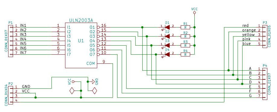
If you gone use several outputs is easier to use a ULN2003 or ULN2803. These are 7 or 8 transistors with the cirresponding R in each base. Don't forget the diode to 12v if you use a mechanical relay, to prevent current spikes that will kill the transistor.
 
Thanks for the input. That really helps me know I'm not crazy looking at the previous schematic. Both your solutions are clear and make sense to me.

Maybe THIS would also work? Plus, get a free stepper motor out of the deal, for some future project. $4 with free shipping.

s-l1600.jpg
 
Alright, so I tried a slight rewire of my setup. Ran one hot leg to the SSR which is pinned directly to the Pi (GPIO 18). Ran the other hot leg directly to the socket for my heating element.

I tried re-running PIDAutotune using both GPIOPWM and GPIOSimple as the type for the actor. Both times it overshot my target temperature and refused to shut off. I checked the light on the SSR and it was off, but continuing to heat anyways. Anyone have advice?

I had a similar problem when first using my system.
On occasion my SSR would "latch" and stay on. Usually after being 100% on for a while, like when bringing mash up to temp.
I found if I killed power to the SSR for a few minutes after I noticed it had 'latched" on sometimes it would go back to working off duty cycle and would be fine for the rest of the mash.
Researching I found most SSR's on the internet are fake, I think mine was a fake Futek.
I purchased some used 40 amp Crydom SSR's on ebay and haven't had a problem since.
When you said the LED light was off on the SSR to me that sounds like the Pi is doing its job.

Cheers!
 

Latest posts

Back
Top