
Gravitysucks
Well-Known Member
That was the first way I tried it, blue wire from the #3 pole of the right side switch block to com(-)gpio #13. Nothing happened when the switch was turned on and was then activated in the UI.The blue wire should go to the - side of the ssr output.
Then I tried it with the blue wire connected to the SSR + terminal (gpio #13) which when set to "relay board" in craftbeerpi reads 12v until you hit the activate button of the craftbeerpi UI at which point it drops to 0v. This didn't seem to work. I tried setting up gpio #13 as gpiosimple which puts 0v on the + terminal when off and 12v when activated but this didn't work either. Not being familiar with how the trigger circuitry of the relay board actually works there is obviously something I'm missing like perhaps the com(-) terminal of that SSR output needs to go to ground? I worked as a marine electrician prior to retiring so I have some familiarity with both high and low voltage systems but this Pi stuff is new ground for me. It's a wonder I haven't fried something yet.
Last edited:


![Craft A Brew - Safale S-04 Dry Yeast - Fermentis - English Ale Dry Yeast - For English and American Ales and Hard Apple Ciders - Ingredients for Home Brewing - Beer Making Supplies - [1 Pack]](https://m.media-amazon.com/images/I/41fVGNh6JfL._SL500_.jpg)


 and got Alexa app "somewhat working" pretty cool! bought a $30 dot on Black Fri just for the brewery.
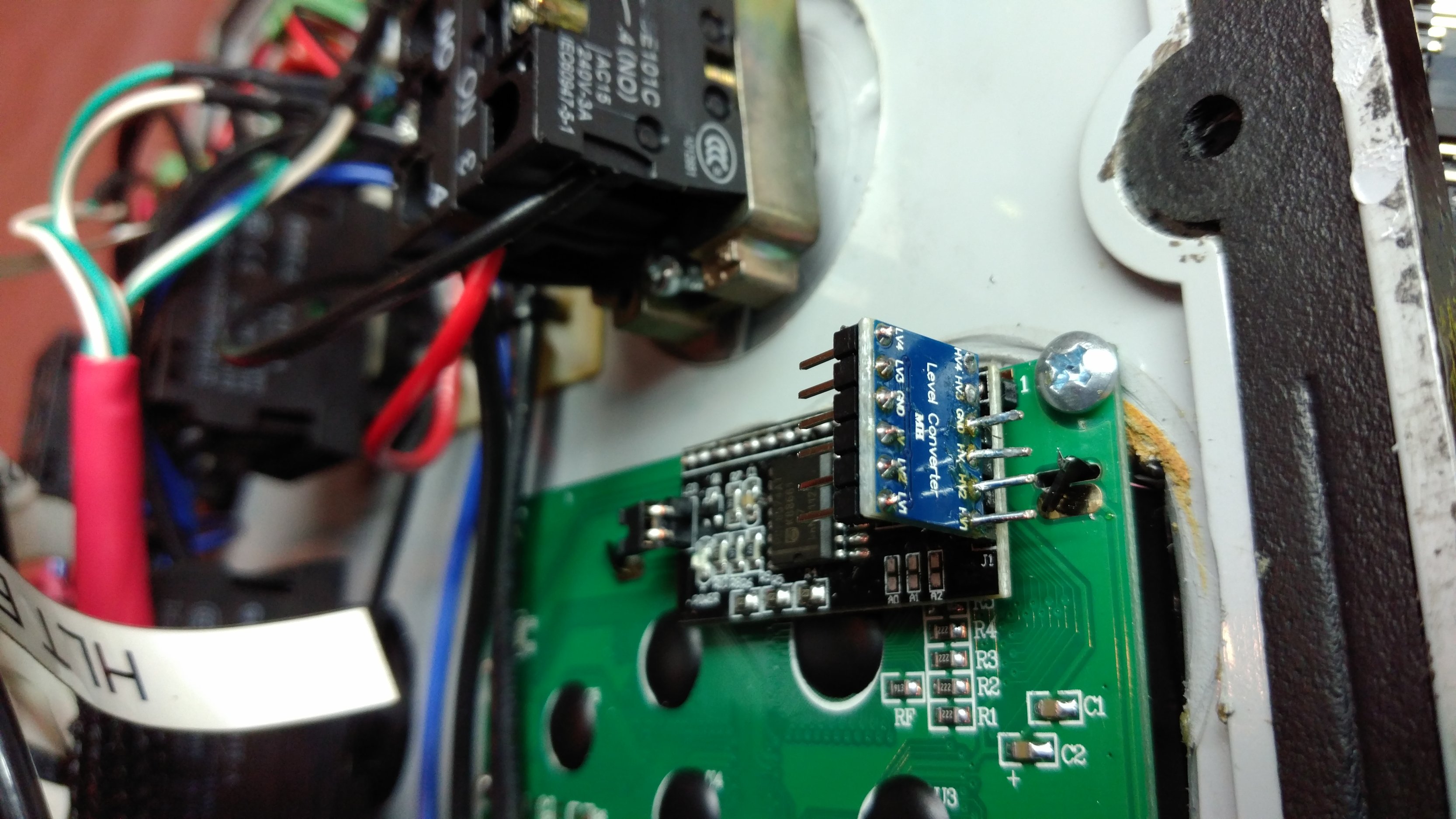
")
