• Please visit and share your knowledge at our sister communities:
  • If you have not, please join our official Homebrewing Facebook Group!

    Homebrewing Facebook Group

Counterflow Chiller Tutorial

Homebrew Talk

Help Support Homebrew Talk:

This site may earn a commission from merchant affiliate links, including eBay, Amazon, and others.
This thread has been very informative, thank you all for your contributions. I have recently moved to 5 gallon all grain after building a mash tun. I've been cooling thus far primitively with a big plastic tub and ice water. I'm over that situation. So on to my questions!

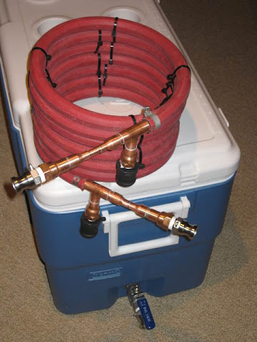
I've looked at a lot of builds and only seen 1 so far that has bare copper wire wrapped around the wort tube creating turbulent flow. Why don't more people do this? Does it make getting the wort tube in the water hose? Does it restrict the amount of water going through the chiller? If so has anyone tried remedying this situation by using a bigger hose? There has to be a reason why everyone doesn't do this. I would appreciate anyone with any experience to shed some light on this for me.

Thanks again!
 
Update on my cfc. I went ahead with tacking bare copper wire around my 15' 3/8 inch od soft copper. It was very difficult to get it in the hose, I had to use a lot of dish soap and elbow grease, in the future I would look for a bigger hose if possible. Since I had the soft copper laying around already I used it, even though it is quite a bit shorter than most people are using.

It works amazingly, I cooled 5.5 gallons of 215 degree wort to 69 degrees using 58 degree tap water using a gravity fed system. I am very happy with the cooling capabilities of such a short hose.
 
Just wanted to add a word of warning based on experience. Three costly mistakes:

  1. I used a "heavy duty" orange hose from Wal-Mart. It tended to collapse on itself and onto the copper tube as I coiled the final assembly
  2. I coiled the hose/tubing in too small a diameter. I used a keg as a form, and between the hose collapsing and the weak spots described below, this significantly diminished the flow rate
  3. Wanting to increase the thermal conduction area of the copper tube and also space it away from the hose, I soldered a length of 14 ga. copper wire to the outside of the tube in a spiral pattern. While this worked to some extent, I believe it created weak spots (particularly where the wire started and ended) that contributed to kinking

Bottom line, it worked pretty well the first time I used it, even with the reduced flow rate. It cooled extremely well. The second time I used it (last week in 24 deg. weather) I had almost no flow and had to raise my kettle up really high to get it to work. I'm pretty sure I kinked it during transport/cleaning/etc.

I was going to give up and buy a Chillzilla but I've reconsidered. My next step is to cut off the hose and copper tubing, use good hose and a larger diameter, and somehow solder everything back together.

Lesson learned: Follow the tutorial closely and you'll be in much better shape. :eek:

I kinked tube is your enemy!
 
I used scrap 3/8" OD copper water pipe for mine, which would have work hardened horribly if I had straightened it out. Some sections needed annealing before it could be worked at all. As I was coiling it back up I could feel it start to kink here and there, but it seems to have turned out OK in the end.

The only slight boo boo I made was forgetting to flux the outside of the coil before attempting to solder the tee assemblies on. I haven't noticed any pinhole leaks so far.

Here it is on top of my MLT. I went with stainless camlocks for the wort connections and polypropylene camlocks for the coolant lines. I think the red hot water hose is slightly niftier than run of the mill heater hose :)

IMG_1162.resized.JPG


Blog post: http://smokedprojects.blogspot.com/2013/02/cool-and-curly-counterflow-chiller.html#
 
I'd have to add a pump to recirculate back into the kettle. Not something I want to do at this point in time.

Still, there is the question of how much time is too long for the kettle to sit there before it's cooled. Any numbers?

I am going to add a spigot to my kettle and have thought about going larger, but then realized that my CFC is only 3/8 so that would probably not do me any good. I can chill my wort more than necessary, but I want to add the ability to chill MORE wort faster. I think the only way to do this is to increase the size of the chiller diameter.

Jamil talks about his "whirlpool chiller" which is a recirculating IC system. I get the idea behind it, but again, it seems like a lot more $$ to spend for a few minutes worth of improvement.


this leads into the question I was going to ask.
is there a mathmatical benifit that you can equate to $$$ spent.
3\8 copper and 5\8 Hose. vs. 1\2 copper and 3\4 hose.
I want to make 2 CF chillers and sell the other but wondered if there was any benifit to going bigger in the grand scheme of most of us only doing 5-10 gallon batches.
love the thread and thanks for all the pics and input. I plan to build system using cam locks.
Cheers!.
 
I used scrap 3/8" OD copper water pipe for mine, which would have work hardened horribly if I had straightened it out. Some sections needed annealing before it could be worked at all. As I was coiling it back up I could feel it start to kink here and there, but it seems to have turned out OK in the end.

The only slight boo boo I made was forgetting to flux the outside of the coil before attempting to solder the tee assemblies on. I haven't noticed any pinhole leaks so far.

Here it is on top of my MLT. I went with stainless camlocks for the wort connections and polypropylene camlocks for the coolant lines. I think the red hot water hose is slightly niftier than run of the mill heater hose :)

IMG_1162.resized.JPG


Blog post: http://smokedprojects.blogspot.com/2013/02/cool-and-curly-counterflow-chiller.html#


:D:drunk::ban:


just what I want to build.....
 
this leads into the question I was going to ask.
is there a mathmatical benifit that you can equate to $$$ spent.
3\8 copper and 5\8 Hose. vs. 1\2 copper and 3\4 hose.
I want to make 2 CF chillers and sell the other but wondered if there was any benifit to going bigger in the grand scheme of most of us only doing 5-10 gallon batches.
love the thread and thanks for all the pics and input. I plan to build system using cam locks.
Cheers!.

I could be wrong, but I think this setup (1/2" copper & 3/4" hose) would increase flow of wort from kettle to fermenter, but would most likely decrease efficiency of the total unit. I dont have the math to follow up my thinking, but logic says the following...
1. the larger the inner circuit the less resistance to flow therefore increased flowrate.
2. by increasing the inner circuit from 3/8 to 1/2 you are increasing the total volume of wort inside the 25foot CFC. Now going from 5/8 to 3/4 will very slightly increase the total volume of the outer circuit, the difference is not as significant total mass as raising the volume of the inner circuit. Essentially you would be using about the same amount of coolant volume inside the CFC to cool a larger amount of wort volume, thus the total efficiency of the chiller would not be as good.
3. With decreased resistance and increased flow rate, your wort would be traveling faster through a less efficient CFC.

Keep in mind, this is all from just logic, and not experience...It may not make that much practical difference, but it might.

If you are set on the 1/2" copper you could make a longer CFC to make up for the inefficiency.

With these things in mind, I have thought about making mine with 3/8" copper and a 3/4" hose. This may be the way to go for people who deal with high ground water temps.

All that said...
Thanks to everyone who contributed to this forum, I have learned a lot. After brewing with my shop owner at the store...and experiencing the difference between cooling times with an IC and a CFC, I'll be building one myself. After talking with him, his experience is that 25' is not enough, but 30' really works well (he has high ground water temps from the city lines). I was going to build 2 25' CFC's and sell one, but he convinced me to buy materials for 3x 30' and sell off the other 2. I had to special order the 100' length of 3/8 copper since no local store carried it, and getting a craftsman rubber hose from Sears. All other parts I was able to pick up from HD or Lowes. (stupid me bought the 1/2-3/8 reducers before thoroughly reviewing this feed, but took them back today and got the right ones.) Total cost was about $215 or about $72 dollars each. I went with 1/2 Brass Tee -->1/2" pipe --> 1/2" MPT adapter --> 1/2' FIP to male and female Garden Hose Thread from my coolant ins and outs so it was a little more expensive. I went with a heavy duty rubber hose too, so that added to the cost, but I wanted more durable than cheap.


The difference between 25' and 30' is going to be negligble, many people have used 50' CFC's and found their efficiency to be barely better than 20-25' ones.
 
Here's my 33' CFC. Going to make some tweaks though. I'm going to put a faucet on the out port for the garden hose so I can regulate the water flow. Also going to add 1/2-1/4 reducer + 1/2 pipe + 1/2 male adapter to the wort in/out for my camlocks.

ForumRunner_20130727_123952.jpg
 
Does anyone know if there is a good reason to not use reclaimed copper refrigerant line from my old AC unit? We got our HVAC system replaced and the copper from the previous AC is just hanging there unused. Should I be concerned about running precious wort through something that once contain freon?
 
Does anyone know if there is a good reason to not use reclaimed copper refrigerant line from my old AC unit? We got our HVAC system replaced and the copper from the previous AC is just hanging there unused. Should I be concerned about running precious wort through something that once contain freon?

Because it has had freon in it.
I would be pissed if someone served me beer made with contaminated equipment.
 
Supposedly freon goes away completely. Just for the record, this was not anything I was considering seriously. It's always better to get the scrap money.
 
I'm not sure about home HVAC but in automotive AC systems oil is mixed with the refrigerant gas to liberate the compressor, it would be impossible to determine if ALL the oil had been flushed from the lines.
 
Supposedly freon goes away completely. Just for the record, this was not anything I was considering seriously. It's always better to get the scrap money.

I'm not trying to smart A$$ but I wouldn't risk any chance introducing bad chemicals in my beer. I would feel bad if someone got sick from drinking it.

Maybe the lubricating oils in the freon can be washed out. Maybe not.
I would scrap it and get some fresh copper.
 
I'm glad this discussion was had on this forum. I read on a distilling forum where a few individuals said yeah go for it.(not to me, just on the thread) I think what started my thought process is someone mentioned using scrap copper they found. Is it really possible to clean the inside of a copper pipe that well? Prob not.
 
Copper is Not that expensive to risk messing up a log brew day and or potentially getting someone sick.
 
I'm glad this discussion was had on this forum. I read on a distilling forum where a few individuals said yeah go for it.(not to me, just on the thread) I think what started my thought process is someone mentioned using scrap copper they found. Is it really possible to clean the inside of a copper pipe that well? Prob not.


If i was looking at saving thousands of dollars, then MAYBE i'd put some weight behind possibly cleaning it.

But your saving $30. Just get 1 less coffee a day and your there in a week.
 
FuzzeWuzze said:
If i was looking at saving thousands of dollars, then MAYBE i'd put some weight behind possibly cleaning it. But your saving $30. Just get 1 less coffee a day and your there in a week.

One less coffee....mmmmmm NOW those are fighting words.
 
Loved Bobby_M's idea and Beer Canuck's "whole works in a bucket" approach. It's 70ish and sunny today which is a lovely day for DIY, but is also a harbinger of impending summer and the mid 70s groundwater temps it brings here in the south. I was worried about reusing the copper from my first homemade immersion wort chiller (already had some kinks started and figured more bending wouldn't do any good on that front). But, it was still plenty fine for a pre-chiller for that dang-near-already-steaming water we get coming out of the tap. Since I planned to put the whole works in a bucket a-la Beer Canuck, why not have that bucket full of ice water and pre chiller? No good reason I could think of.

So, tap water goes into the bottom of the bare coil (red hose) and exits the top of the coil into the counterflow chiller. I'm sure there's a more elegant and/or effective way to do this, but ran the wort out tube through a hole in the bucket and scooged the thing shut with silicone. A hand tubing bender was essential (about $16 at lowes) to make a couple of tight bends to line everything up without kinking. Yes, there's pretty nearly a kink near the top of the pre-chiller. Don't judge me.

Haven't tested with ice water, but 200deg wort in (water for test) comes out 65 with 59deg tap water and valve on the kettle about 2/3 open. Hooked the output to a lawn sprinkler. I've named it Ghostface Chillah...

I'm thinking of adding a thrumometer to the output along with some sort of venturi apparatus. By thrumometer, I mean a cheap stick on fermometer stuck to something suitable.

CCC1.jpg


CCC2.jpg
 
I am using these reducers http://www.amazon.com/gp/product/B000LEHDLY/?tag=skimlinks_replacement-20 but I can only get the copper tubing through the small end of the reducer so that an 1/8 of an inch is sticking out before the whole copper assembly jams. The big end of the reducer slips inside the T fitting, it is the same diameter as the copper pipe. I tried reaming it out with a 3/8" drill bit, and the bit goes clear through the reducer. Any suggestions?
 
Last edited by a moderator:
I finally got the copper tubing through the adapter. Part of the tubing wasn't perfectly round so I cut off part of the tube and with some twisting and extra muscle I got the adapter on far enough. Use a hacksaw or bandsaw to cut the tubing, the tool used to cut copper pipe will just kink the soft copper.
 
Sweet, three posts in a row. Thanks to Bobby M for the design and tutorial. As I mentioned above the reducers that I used slip into the T fitting so I had 2 lengths of copper left over. I needed four 1/2" couplers, which are the same diameter as the T fitting and elbows, to attach the garden hose fittings to the copper pipe and also the second reducer to the threaded copper fitting (http://www.amazon.com/gp/product/B000O1DTRQ/?tag=skimlinks_replacement-20). I also added some Bobby M parts: thermometer, stainless T, and the thermometer compression fitting. I am no expert at soldering, but this was an easy project to finish in an afternoon.
ImageUploadedByHome Brew1397102242.683703.jpgImageUploadedByHome Brew1397102273.050091.jpgImageUploadedByHome Brew1397102320.529453.jpg


Sent from my iPhone using Home Brew
 
Last edited by a moderator:
This thread should be a sticky. Bobby, is a great contributor to the home brew community. He's pretty humble about it which makes him even more appreciable. No way to say to much thanks to Bobby_M.
 
I know this is an old thread but I can't seem to see the photos of how its made. It's just a small blue box with a "?" in it. Just wanted to give a heads up if anyone else is experiencing this.
 
Sweet, three posts in a row. Thanks to Bobby M for the design and tutorial. As I mentioned above the reducers that I used slip into the T fitting so I had 2 lengths of copper left over. I needed four 1/2" couplers, which are the same diameter as the T fitting and elbows, to attach the garden hose fittings to the copper pipe and also the second reducer to the threaded copper fitting (http://www.amazon.com/gp/product/B000O1DTRQ/?tag=skimlinks_replacement-20). I also added some Bobby M parts: thermometer, stainless T, and the thermometer compression fitting. I am no expert at soldering, but this was an easy project to finish in an afternoon.
View attachment 192201View attachment 192202View attachment 192203


Sent from my iPhone using Home Brew

Do you remember where you got that thermowell? I would like to add one to a t but they all seem to long to fit.
 
Last edited by a moderator:
Hey everyone. Just went out and bought almost all of the items. Just wanted to clarify, I saw in another thread that instead of the 1/2 to 1/4 reducers he used 1/2/ to 3/4 reducers. Which of the two would be more advantageous?

Also I can't seem to see any of bobby's pictures of the build. I can see everyone else's pictures on the thread except his? would anyone know where i could view them to make the build go easier?
 
Tutorial images no longer work. I just ordered the parts and now I can't see the tutorial!!
 
Just to balance out all the post whoring, I thought I'd actualy put something a little more substantial together.

This is the cheapest way to put a CFC together and doesn't use any pricy compression fittings. It requires soldering, but you ought to know how to do that already. No? Shame. Here's what we're building:

cfc.jpg


Part list:

(1) 12" x 1/2" copper pipe
(2) 1/2" copper TEEs
(2) 1/2" x 1/4" copper reducers
(1) 25' x 3/8" OD soft copper tubing
(1) 25' x 5/8" ID rubber garden hose (make sure it's rubber. It will be the only one that does NOT say "do not use with hot water".)
(4) hose clamps.


cfc3.jpg


You'll also need some emory cloth (sandpaper), a round wire brush, flux, solder, tubing cutter, and a propane torch.

The first step is to create the end assemblies:
Completely clean the 1/2" copper pipe by sanding it with emory cloth, then cut it into six 2-inch pieces with the tubing cutter. Clean the insides of the Tees and reducers with the round wirebrush. Apply a liberal amount of flux paste and assemble to look like this:


cfc1.jpg


Apply the propane flame and keep it moving but focus mostly on the Tee. Keep testing the temp by removing the flame and touching solder to the joint. If it doesn't flow, apply a little more heat. Don't overheat. You should see the solder being sucked into the joint. A solder joint does not seal due to an apparent bead on the outside of the fitting so don't build it up too much. Once it starts dripping out and falling on the floor, you have more than enough in the joint.

Before moving on, you must drill out the stops inside the reducer fittings with a 3/8" drill bit. There's a nub sticking out inside there that is meant to stop the 3/8 tubing from going all the way through the reducer. This is precisely what we WANT to happen.

Any chance you could fix the images for these? Or are they gone now?
 
Back
Top