Control Panel Wiring Check

Homebrew Talk - Beer, Wine, Mead, & Cider Brewing Discussion Forum

Help Support Homebrew Talk - Beer, Wine, Mead, & Cider Brewing Discussion Forum:

This site may earn a commission from merchant affiliate links, including eBay, Amazon, and others.

SalParadise

Active Member
Joined
Sep 4, 2020
Messages
35
Reaction score
22
Location
Grand Rapids
Hi All!

Long time lurker, first time poster here. First off – the proposed diagram is largely based on the work I’ve found on this forum from user @doug293cz. After spending so much time over the past year pouring over various diagrams, I’ve become irrevocably partial to his – which is why this diagram matches the look and layout of the work he’s done. I feel the need to point this out up front, as I’m not trying to pass these off as diagrams that a well-known forum member has provided – If they look like Doug’s it’s because I shamelessly copied his work and made some minor adjustments to suit my needs. If anyone is bothered by this, please let me know and I’ll adjust the diagram as needed. HUGE thanks to Doug for all the attention he’s given this forum.

A few years back I teamed up with a couple of friends and built out a setup with 30 gallon kettles, which was great for a while - we were all too busy to brew more than once every other month and splitting the batches three ways worked out nicely. However, I quickly realized that we don't always agree on what to brew and the more I brewed, the more often I wanted to brew. So, while we still brew as a group every so often, I found myself brewing 5 gallon batches again. I decided last year I'd like to retire my burners and go full electric. Since then I've spent a fair amount of time reading up on the topic, both here and over at Kal's site and thinking through how'd I'd like the final panel to function. Since outfitting kettles for electric brewing is far cheaper than building a control panel for each system, I thought it might be clever to save some money and design something that would work great on both my small system and the group's larger system.

Over the past week, I spent some time finally putting together a diagram. My plan here isn’t to build this panel all at once, but rather step into things as my budget allows. I’m attempting to begin with the end in mind to avoid having to replace components, wiring, etc. down the road with units rated for the higher amperage. Initially this panel will likely start as an eHERMS system (since I recently scored a deal on Craigslist that was too good to pass up) and grow into something along the lines of this proposed design.
When brewing on the small system, I’ll have 30 amps to play with, so plan on running a single element at a time. On the bigger system, we have 50+ amps available, so I was planning on setting it up for back to back batches. We currently don’t brew back to back batches, but my thought was it might be nice to be able to do so, or to be able to fire a pair of elements in one kettle at the same time to reduce the ramp time for heating 20+ gallons of water.

The eHERMS setup I bought is a 10 gallon Boilermaker with the BoilCoil, HERMS coil and all the fittings. It came with a controller that used an Auber SYL-1512 and a DSPR1. The wiring in the controller had enough red flags that I knew from the time of purchase that I’d be starting over from that end – essentially, I have an enclosure with a heatsink and a few components to get me started.

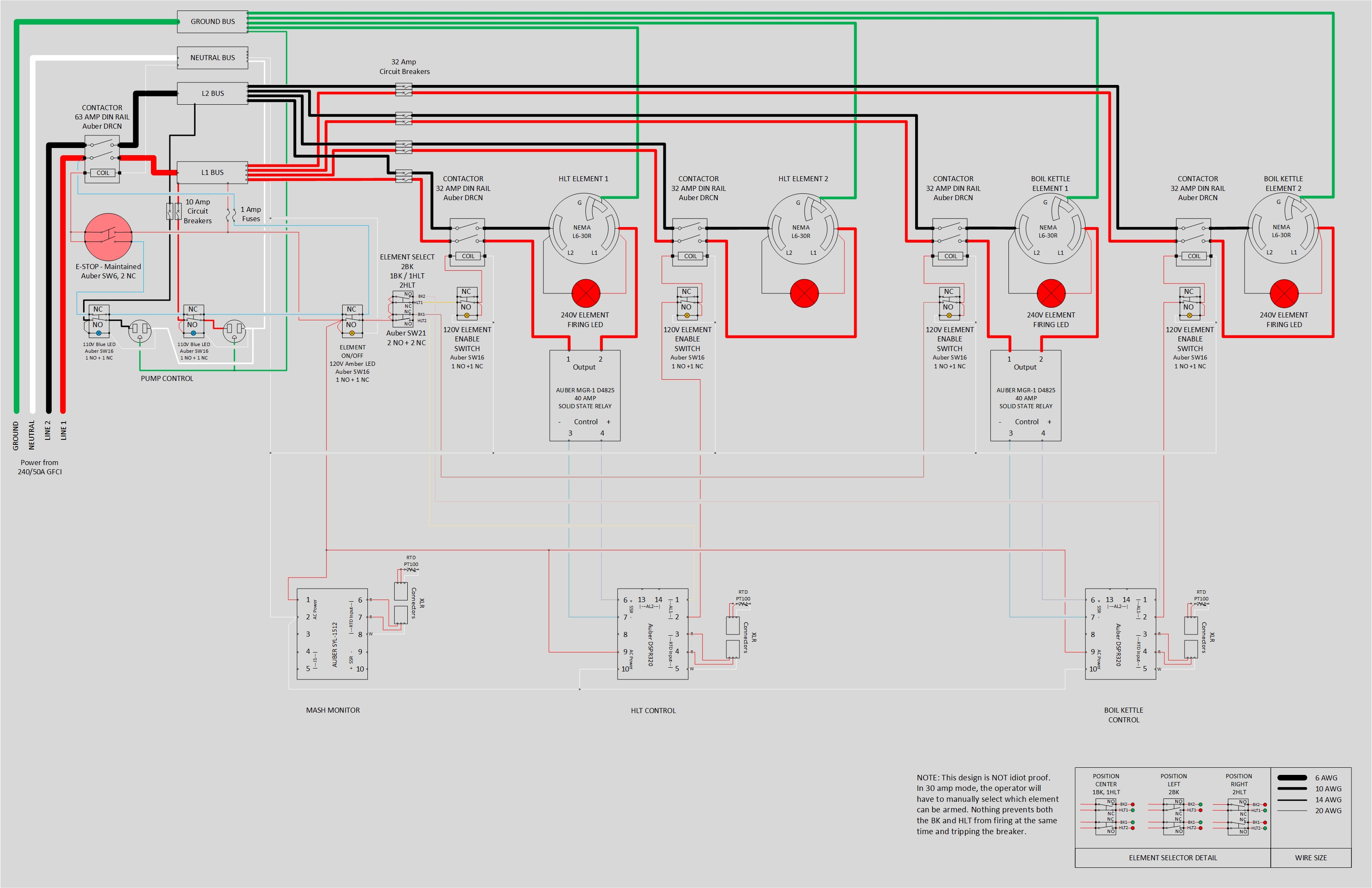
Here’s the diagram I worked out (read: copied and slightly modified). A few notes on the diagram:
  • The element detail in the bottom-right was to help my non-electrical engineer brain reason through how that switch would work.
  • Secondary HLT and BK elements are using a contactor only. This was based on some directions over at Auber’s site. The idea is that these elements will only ever be fired at 100% duty cycle once or twice per brew session to help with the ramp times. The contactors will be controlled by the relay circuit in the DSPR320.
A few questions:
  • Does anyone see anything glaringly wrong with this design?
  • Is there anything I can do better / smarter / cleaner?
  • Assuming I wired this up as shown, is there any reason to split the neutral lines up any more than I have?
  • When powered by 30 amps, the selector switch doesn’t prevent me from doing something silly like firing both the HLT and BK at the same time and tripping a breaker. To overcome this, I’ve added lighted ‘element enable’ switches for BK1 and HLT1. The secondary elements in 30 amp mode will be physically disconnected.
    • This still allows for the possibility that I’ll stupidly arm both elements (turning on both element enable switches at the same time) and trip a breaker – is there a better way to handle this? I played around with trying to add a selector switch to toggle between 30 and 50 amp mode, but quickly wound up stacking a bunch of switch blocks and wiring myself into a corner. On the other hand, if my mistake only leads to tripping a breaker is it even worth worrying about?
    • Should I consider adding element enable switches for the secondary elements? When working in 30 amp mode, the DSPR320 could still pull the contactor down on those elements and feed live power to the unplugged outlets. Part of me feels adding element enable switches on the coil side of this circuit is overkill, but part of me feels having live, unplugged outlets isn’t the smartest thing to do at this amperage.
If you’ve made it this far, thanks for listening to me ramble!

-Sal

ElecBrewControlPanel_v1.1.jpg
 
Pretty good first attempt at a relatively complex design. It does have some issues however.
  • First, it will never power up. There is a mistake in the "safe start" circuit wiring. Rather than the blue wire connecting to the L1 bus after the main power contactor, it needs to connect to L1 upstream of the main power contactor. It should be fused near the point where it connects to the incoming L1 feed.
  • The SW6 "Main Power/E-Stop" switch needs to be 2-NC blocks rather than 2-NO. With 2-NO you have to "hit" the mushroom to close the switches to turn the power on, and pull & twist the mushroom to turn the power off. You want hitting the mushroom to shut things down, and you don't want to have to pull & twist for emergency shut down.
  • The alarm relays on the DSPR320's are incorrectly wired. They should not have a neutral connection at all. Terminal #2 should be connected to the corresponding terminal on the SW21 selector switch.
I am impressed that you got the wiring of the SW21 selector switch correct, which requires understanding how the NC blocks behave on the 3 position switches.

They way you have implemented the three way selector depends on correctly programming the DSPR320 alarm relays in order to prevent turning on three elements when in the two BK or two HLT element positions. This is likely to be an error prone process, but should have no worse consequences than tripping the main breaker if done incorrectly.

Brew on :mug:
 
Pretty good first attempt at a relatively complex design.
Thanks! It helped to have really good source material :thumbsup:

First, it will never power up. There is a mistake in the "safe start" circuit wiring. Rather than the blue wire connecting to the L1 bus after the main power contactor, it needs to connect to L1 upstream of the main power contactor. It should be fused near the point where it connects to the incoming L1 feed.
Well that's embarassing - not sure how I missed that. Thanks for the catch!

The SW6 "Main Power/E-Stop" switch needs to be 2-NC blocks rather than 2-NO. With 2-NO you have to "hit" the mushroom to close the switches to turn the power on, and pull & twist the mushroom to turn the power off. You want hitting the mushroom to shut things down, and you don't want to have to pull & twist for emergency shut down.

Hitting the mushroom to power down is exactly what I was intending. I guess I assumed that the "normal" position was with the button depressed, and in that mode I'd want the contacts open. Good to know its the opposite of what I was thinking, I'll update accordingly.

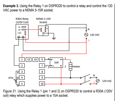
The alarm relays on the DSPR320's are incorrectly wired. They should not have a neutral connection at all. Terminal #2 should be connected to the corresponding terminal on the SW21 selector switch.

I based that wiring on what I found on Auber's site:
AuberRelay.png

Looks to me that with their diagrams they're breaking on the neutral wire. Everywhere else in this diagram and in the others I've studied, they all break on a hot leg. Which, now that I'm thinking about it more makes a lot more sense - after all, when wiring a light switch in a house, you always break the hot leg.

I am impressed that you got the wiring of the SW21 selector switch correct, which requires understanding how the NC blocks behave on the 3 position switches.

Thanks! Sketching up the possible positions helped me wrap my head around it, I left it on the diagram in hopes that it might help others as well.

They way you have implemented the three way selector depends on correctly programming the DSPR320 alarm relays in order to prevent turning on three elements when in the two BK or two HLT element positions. This is likely to be an error prone process, but should have no worse consequences than tripping the main breaker if done incorrectly.

I didn't even consider this scenario - seems so obvious now that you point it out! Agreed that relying on the operator (me, several homebrews in on any given brew day) to remember to adjust the relay programming is certainly going to be error prone. I'll add some illuminated 'element enabled' switches to at least make this a little more obvious. Since I won't acutally be building this design initially, I have more time to research and see if I can come up with a clever way to configure this with a 30 amp / 50 amp selector switch. I'm not sure how many contact blocks a single switch can support before the actuation becomes physically difficult to operate, but I'm guessing I'll run out of depth in my panel once I start stacking more than two pairs anyways.

Regarding the illuminated 'element enable' switches - I drew them up this way, because Auber sells that switch with the option for 1 NC and 1 NO block. Since the NC block isn't even used, would I even need to physically attach it? Without it, will the two position switch feel like it's missing its 'off' detent?

Also, because I want both DSPR320's to always be powered on for programming reasons, are there any concerns about 'dry firing' the SSRs themselves? The contactor will be open, per the 'element enable' switch. Curious if cycling the SSR without any load attached could cause issues like premature failure of the SSR itself.

Here's an updated diagram - Does it look like I've cleaned everything up per your suggestions?

ElecBrewControlPanel_v1.2.jpg
 
Redrew the safe-start interlock to remove a redundant switch from the previous design. Also added a mini 2-in-1 voltmeter/ammeter (Top left near main contactor, Auber MVA-22R).

I'm thinking I should probably add some fuses to the new meter, but do I fuse both legs since it's running 240 volt? Are fuses even necessary for the meter? Other diagrams I've looked at, including this one don't fuse the element firing LEDs at all.

ElecBrewControlPanel_v1.3.jpg
 
Last edited:
...

I based that wiring on what I found on Auber's site:
View attachment 697165
Looks to me that with their diagrams they're breaking on the neutral wire. Everywhere else in this diagram and in the others I've studied, they all break on a hot leg. Which, now that I'm thinking about it more makes a lot more sense - after all, when wiring a light switch in a house, you always break the hot leg.

...
No, they are breaking the hot line. They should have had the wire from terminal 2 of the DSPR to the R30A relay colored red to make things more clear.

Brew on :mug:
 
...

Regarding the illuminated 'element enable' switches - I drew them up this way, because Auber sells that switch with the option for 1 NC and 1 NO block. Since the NC block isn't even used, would I even need to physically attach it? Without it, will the two position switch feel like it's missing its 'off' detent?

Also, because I want both DSPR320's to always be powered on for programming reasons, are there any concerns about 'dry firing' the SSRs themselves? The contactor will be open, per the 'element enable' switch. Curious if cycling the SSR without any load attached could cause issues like premature failure of the SSR itself.

...
I think the switches should operate fine with only one switch block attached. It they do feel odd that way, you can always just mount the unused switch block.

Triggering an SSR with no load attached is not an issue. The control input is electrically isolated from the actual switching element and trigger circuitry. The control input turns on an LED inside the SSR, and the light from that LED is detected by a photodiode which electrically signals the trigger circuit.

Brew on :mug:
 
...

They way you have implemented the three way selector depends on correctly programming the DSPR320 alarm relays in order to prevent turning on three elements when in the two BK or two HLT element positions. This is likely to be an error prone process, but should have no worse consequences than tripping the main breaker if done incorrectly.

Brew on :mug:
The above is incorrect. The way you have the three way selector switch wired does prevent firing more than two elements at a time.

Brew on :mug:
 
Redrew the safe-start interlock to remove a redundant switch from the previous design. Also added a mini 2-in-1 voltmeter/ammeter (Top left near main contactor, Auber MVA-22R).

I'm thinking I should probably add some fuses to the new meter, but do I fuse both legs since it's running 240 volt? Are fuses even necessary for the meter? Other diagrams I've looked at, including this one don't fuse the element firing LEDs at all.

View attachment 698288
This design looks good. I didn't find any obvious errors.

I wouldn't fuse the meter. In case the lead wires short out to something, they should "self fuse" without creating significant collateral damage inside the enclosure. Same with the lead wires for the element firing lights - if they are fine wires. If they are larger wires, they will carry the full 30/50A long enough to trigger the main breaker without starting a fire inside the enclosure.

You can always add fuses to all of these leads if you really want to. If you do, all hots should be fused as they can source current independent of all the other hots. Neutrals don't need fuses, since they cannot source current.

Something to watch out for when you start testing your panel. The element firing lights will light up even when the SSR is not triggered if the corresponding element is unplugged. This is due to the low level off leakage inherent in SSR's.

Brew on :mug:
 
No, they are breaking the hot line. They should have had the wire from terminal 2 of the DSPR to the R30A relay colored red to make things more clear.

Agreed, this would have made it much more clear. Thanks again for the catch!

I think the switches should operate fine with only one switch block attached. It they do feel odd that way, you can always just mount the unused switch block.

Big box 'O parts arrived today - Can confirm the switches don't feel any different with one contact block removed. When I asked that question, I didn't realize that they come with both blocks anyways so my underlying thought of not having to purchase the 'extra' blocks was a moot point anyways.

Triggering an SSR with no load attached is not an issue. The control input is electrically isolated from the actual switching element and trigger circuitry. The control input turns on an LED inside the SSR, and the light from that LED is detected by a photodiode which electrically signals the trigger circuit.

Thanks for the confirmation. Your additional explanation sent me down a 45 minute rabbit trail on youtube learning more about how SSRs operate :D

The above is incorrect. The way you have the three way selector switch wired does prevent firing more than two elements at a time.
Something to watch out for when you start testing your panel. The element firing lights will light up even when the SSR is not triggered if the corresponding element is unplugged. This is due to the low level off leakage inherent in SSR's.

You know, I'd stared at this diagram so many times that when you suggested that the wiring allowed for three elements to fire I didn't even question it. Also, somewhere in the back of my mind was your comment about the 'element firing' LEDs lighting up due to current leakage of the SSR. Adding the additional 'element enable' switches seemed an obvious solution. Having since reviewed the diagram a dozen or more times, I decided the 'element enable' switches on the secondary elements are redundant. As you noted, the initial wiring of the three-way switch prevents three elements from firing. I've left the element enable switches on the primary elements, as at some point in the life of this controller I'll likely be running it at my house on 30 amps and at my buddy's house on 50 amps in back to back mode. Those extra element enable switches were the only way I could sort out how to allow me to build a panel that could either fire one element at a time when running on a 30 amp supply or fire both when 50 amp supply is available.

I wouldn't fuse the meter. In case the lead wires short out to something, they should "self fuse" without creating significant collateral damage inside the enclosure. Same with the lead wires for the element firing lights - if they are fine wires.

Thanks for the peace of mind on this one. I plan on using 18 AWG wire to connect the element firing LEDs, and meter - so no fuses it is.
 
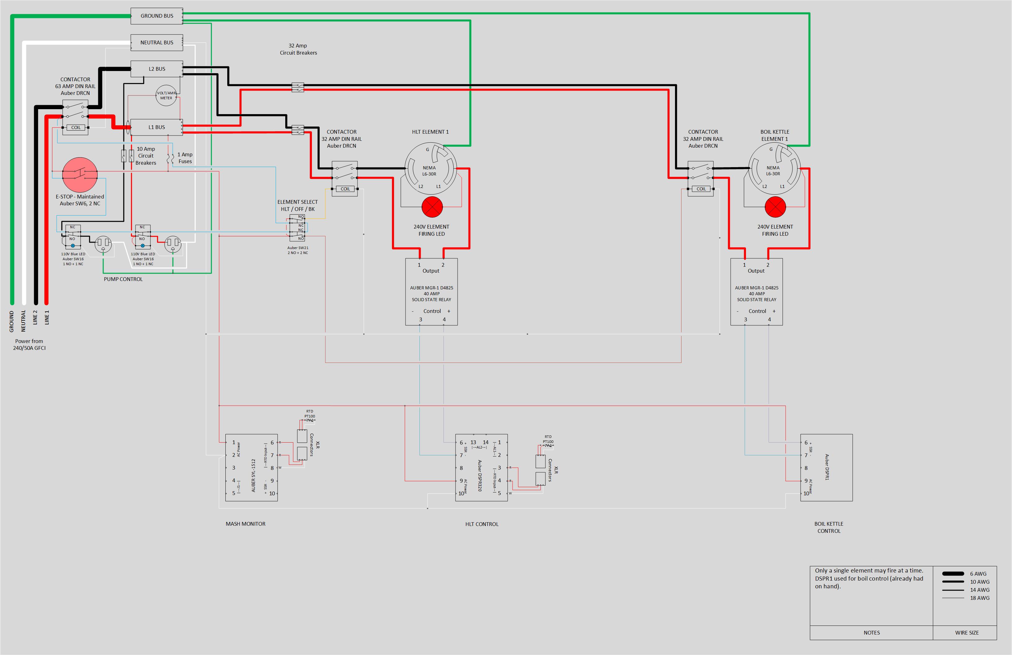
Here are the final diagrams. To meet my initial goal of designing something that could scale as my budget allowed, I've drawn up three diagrams. Essentially, I started with the 4 element diagram and removed components as needed to ensure I wouldn't have to replace anything to achieve the 4 element design;
  • Phase 1 - 2 Elements, 30 amp supply - this is really just a clone of some of the diagrams I found here by @doug293cz
    Phase1.jpg
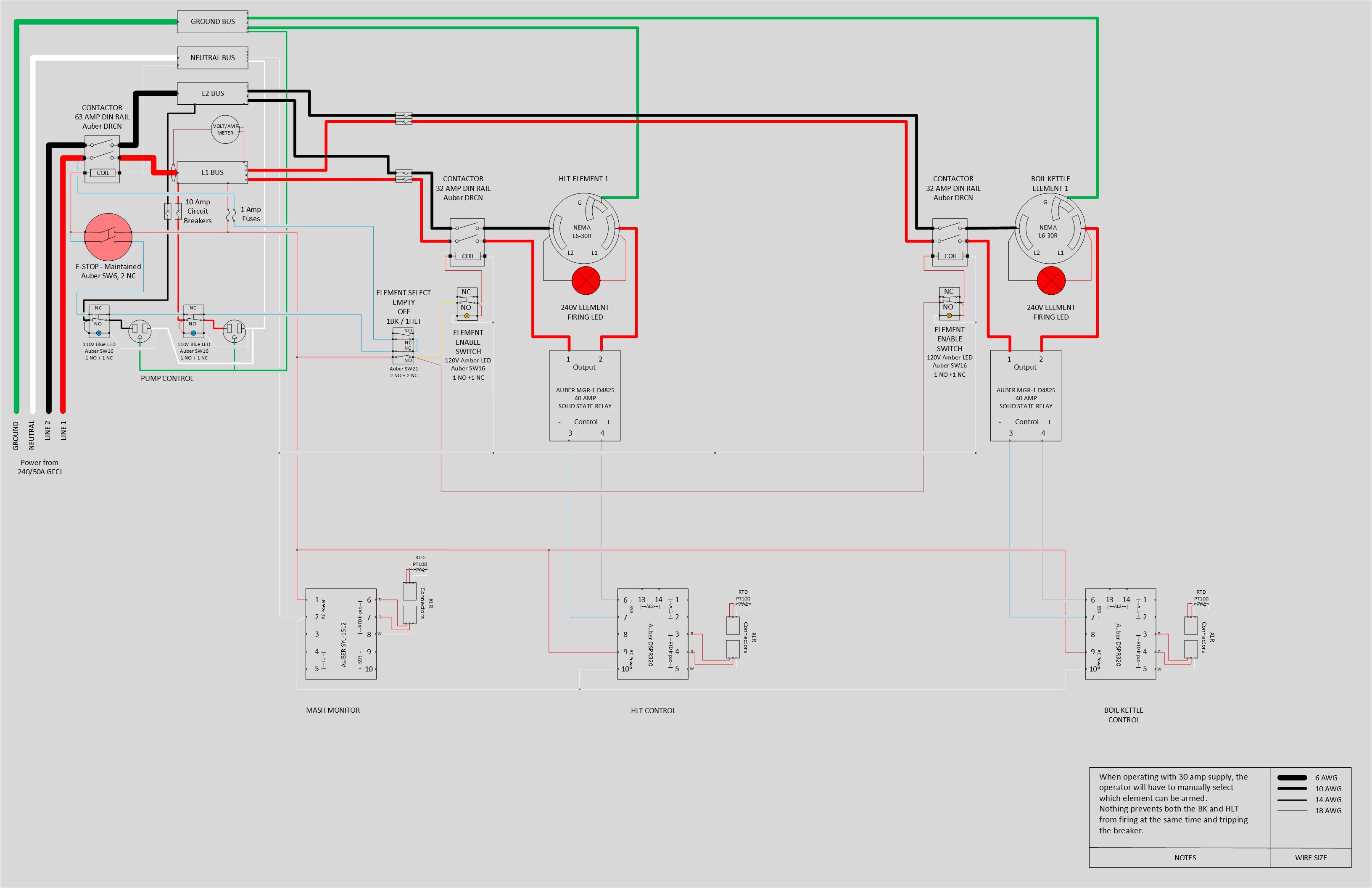
  • Phase 2 - 2 Elements, 30 or 50 amp supply. Ability to run back to back batches when 50 amps are available or run a single element at a time with the element select switches.
    • The element select switch looks a little weird here because it could be replaced by a two-position on/off switch. The three-position switch and contact blocks are used simply because at this point I'll already have them on hand.
      Phase2.jpg
  • Phase 3 - 4 Elements, 50 amp supply. The diagram initially posted, but redrew the safe-start interlock and removed some redundant 'element enable' switches.
    Phase3.jpg

I also spent a ridiculous amount of time drawing up my panel layout. I actually managed to get the full 4 element design crammed into my enclosure (12 x 10 x 8)... at least on paper. The size of the contact blocks on the back of the switches would've made the execution of this plan impossible. Also, while its sure easy to draw with incredible precision, actually cutting the holes with a handheld drill is an entirely different matter. Should I ever make it to building the 4 element design, I'll be buying a new enclosure.

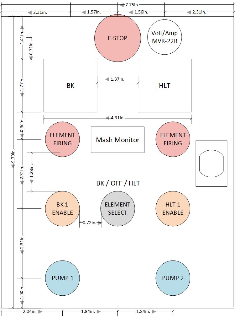
Here's the panel layout I finally settled on for 'phase 2.' I plan on cutting all holes in advance so when I decide to move to back to back batches, I won't have to worry about all the metal shavings making a mess of the inside of my controller. I know the dimensions look super weird but bear in mind that 1. I'm drawing this in Visio (and therefore clearly must hate my life) and 2. I've subtracted the dimension of the gasket from the door to give myself the actual working area to lay everything out on. It's actually drawn on a 1:1 scale to make it easier to check fitment of all the parts.

FrontPanel-Small.jpg


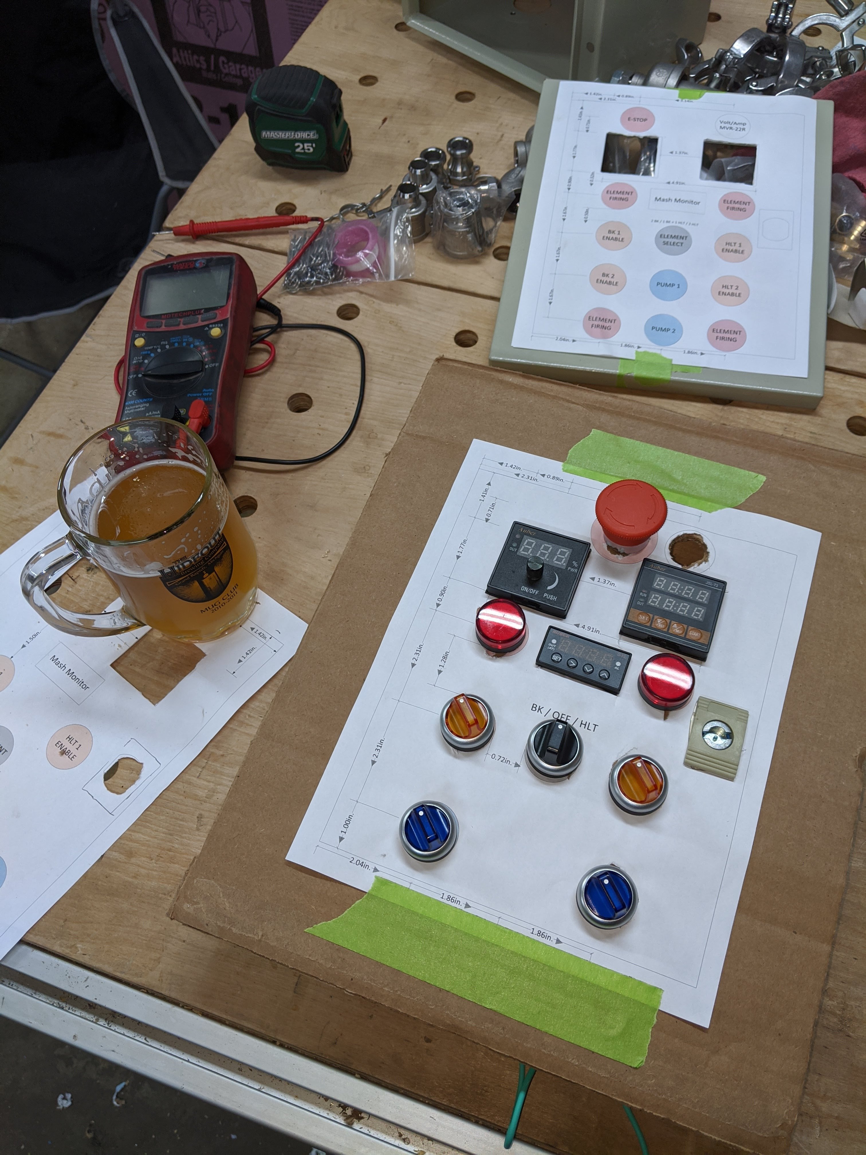
Final step before cutting some holes in the enclosure - Lay it all out on cardboard:

CardboardPanel.jpg
 
Few questions:

Maybe I do not understand how a 220 VAC GFCI works. If you tap off your 220 VAC to make 120 VAC, wouldn't a GFCI see that as a ground fault and trip? As in 15 amps leave L1, 14 amps goes through your heating element and returns through L2, 1 amp splits off at the tap and returns through the neutral.

I see 4 element firing LEDs but your panel shows 2.

When you are running two elements on the HLT or MT, on of the elements is 100% full power or off. How does that work? Do you run at 50% through 100% power. (l1 runs 0-100 + L2 runs 100%) Or you turn off #2 so you can run at 0%-50%. I am deep Auber knowledge. Isis it smart enough to understand and manage the two elements such that they behave as one?
 
Few questions:

Maybe I do not understand how a 220 VAC GFCI works. If you tap off your 220 VAC to make 120 VAC, wouldn't a GFCI see that as a ground fault and trip? As in 15 amps leave L1, 14 amps goes through your heating element and returns through L2, 1 amp splits off at the tap and returns through the neutral.

...
In a 240V split phase w/neutral GFCI, both hots and the neutral wires run thru the current sensing coil. The coil measures any current imbalance among the three wires. If one hot is carrying 15 A flowing to the loads, and the other hot is carrying 14 A flowing from the loads, and the neutral is carrying 1 A flowing from the loads, then you have 15 A going to the loads and 15 A from the loads. Everything is in balance.

Brew on :mug:
 
I see 4 element firing LEDs but your panel shows 2.

Correct, this panel layout corresponds to the 'phase 2' diagram - where I'll actually only have two elements. Fitting everything for all 4 elements in this small enclosure just wasn't practical.

When you are running two elements on the HLT or MT, on of the elements is 100% full power or off. How does that work?

I'll be using Auber's DSPR320 for mash and boil control eventually (phase 1 and 2 diagrams are utilzing some other parts I already had on hand). The relay encoding on the DSPR will take care of driving the secondary elements in the 4 element design. These controllers can be configured to close the contact on the relay (which in turn drives the contactor for the corresponding element) in a number of ways. For prepping the strike water, my plan is to pick a temperature (let's call it T1) slightly below what my typical desired strike temp is (T2) is and program the controller to fire both elements until it reaches T1, then open up the contact for the secondary element and use a single element to bring the temp to T2 and hold until I manually advance to the next step. The idea here was to minimize the need to reprogram the relay contact between brew sessions. Boil profile will be similar, but set to hold temp to just before boiling and sound the alarm when it reaches that set point. In theory this should get my attention to make sure I don't miss my FWH or have any boilovers. We'll see how it all works out in practice once this thing is built. Also, if you give the user's manual a read and have any questions, Auber's support was very responsive and helpful in getting the relay encoding worked out.

The coil measures any current imbalance among the three wires. If one hot is carrying 15 A flowing to the loads, and the other hot is carrying 14 A flowing from the loads, and the neutral is carrying 1 A flowing from the loads, then you have 15 A going to the loads and 15 A from the loads. Everything is in balance.

Since I bought a spa panel that had a neutral and two hots all built into the enclosure, I didn't even think about how it works - thanks for the clear explanation! 👍
 
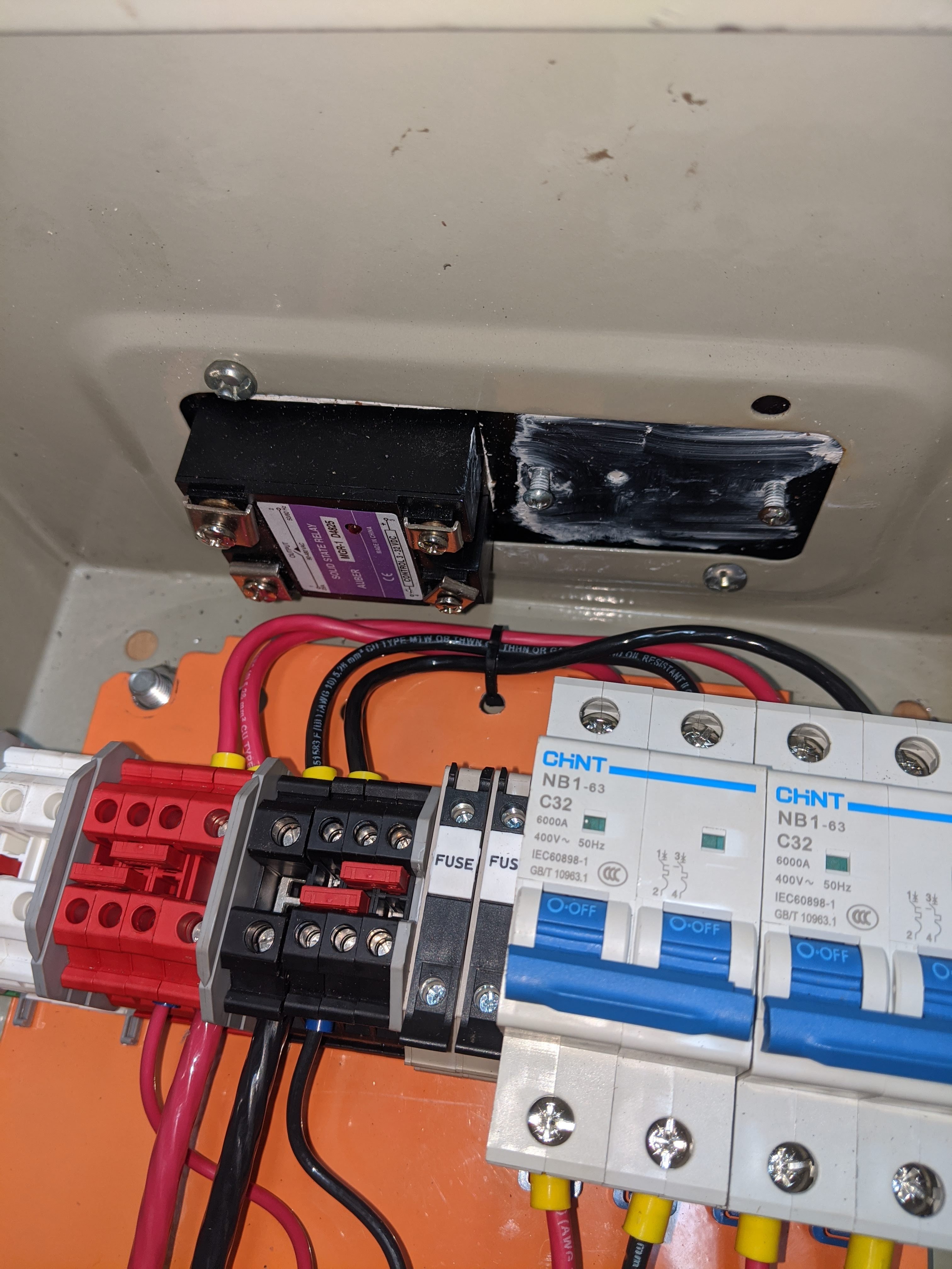
Started wiring things up this evening and am getting concerned about the available space in this smaller enclosure. Anyone know how hot the SSRs will get when the panel is running? They'll be mounted to a heatsink that came with the enclosure (about 7" wide x 5.5" deep x 1.25" tall). Does having these wires (between L1/L2 bus and 32 amp breaker in my diagram concern anyone else?

IMG_20200917_221103.jpg
 
I don't see anything to be concerned about. The heatsink should stay cool enough that you can hold your hand on it when the SSR is operating. You can always add a fan to blow air across the heatsink if it gets too warm. The max thermal dissipation from the SSR should be less than 35W.

Brew on :mug:

Awesome, thanks for giving me the confidence to continue!
 
Last edited:
I agree you should be fine. SSRs are designed so the heatsink side gets hot. If the opposite side got not, there is no way to draw the heat away.

If you wanted to take a suspenders and belt approach, you can use Teflon insulated wire. Make sure you observe rules about minimum wire size.
 
I don't see anything to be concerned about. The heatsink should stay cool enough that you can hold your hand on it when the SSR is operating. .

Not exactly. SSR is based on triacs. And maximum allowed triac's junction temperature usually around 120C (250F). Considering thermal resistance junction-triakc enclosure-SSR hotplate-heatsink we can estimate maximum allowed heatsink temperature around 90C (~190F). It's not recommended to run triac constantly near it's maximum allowed junction temperature and better to keep it at least 20-30C below. So if your heatsink temperature is around 60C (140F) it's absolutely OK.
 
Not exactly. SSR is based on triacs. And maximum allowed triac's junction temperature usually around 120C (250F). Considering thermal resistance junction-triakc enclosure-SSR hotplate-heatsink we can estimate maximum allowed heatsink temperature around 90C (~190F). It's not recommended to run triac constantly near it's maximum allowed junction temperature and better to keep it at least 20-30C below. So if your heatsink temperature is around 60C (140F) it's absolutely OK.
Auber recommends keeping the temp of the SSR base plate below 70°C, so a 60°C heatsink temp (at base, directly opposite center of SSR) sounds about right. (Of course these are all estimates since we don't know all of the thermal resistances.) "Too hot to touch" is about 50°C (122°F), so this seems reasonable for the portions of the heatsink easily reachable with hand/fingers.

I don't think there is any conflict between what we both said.

Brew on :mug:
 
Going into this I was thinking this enclosure would be plenty big enough - if I had to do it all over again, I'd have just completely scrapped the panel I started with and purchased a bigger enclosure. Pretty sure my hands doubled in size as soon as I reached inside my enclosure - it's tight in there.

Mostly all wired up, waiting on a few more components. Realized that the smaller terminal blocks I purchased would likely be overloaded in the way they're wired up now - bigger ones on the way.

Front.jpgBottom.jpgDoor.jpgInside.jpg
 
Last edited:
Powered it up this evening and am pleased to report that all the smoke stayed inside the electronics, where it belongs :thumbsup:

Still waiting on a handful of parts, but hope to be brewing on it by the weekend!
 
Prior to powering everything up for the first time, I went over everything with my multimeter checking all my switches and ensuring I had a path to ground from the kettle body back to the ground pin on the power plug - I'm glad I did - found an issue with how I'd wired up the safe-start interlock. Diagram was correct, but I managed to wire it up wrong initially. Also discovered one of my switch contact blocks wasn't fully actuating so I replaced the block.

Just finished brewing my second batch on the new system and I'm really liking it. Still getting used to all the changed processes in my brew day and fine tuning things. I worked out a no-hose change design now that I've got a second pump and that's been helping keep things a bit cleaner on brew day.

Overall, super glad I made the switch - Thanks to everyone for all the input on getting this project moved from an idea to a reality!

Here's an action shot for those interested. At this point I'm still boiling on propane, but the panel is fully ready for a second element.

BrewDay.jpg
 

Latest posts

Back
Top