
I'm looking for some perspective on this project of mine... I want to rebuild/redesign a control panel that will control every single aspect of my entire brewery. The kicker is that I want to use a PLC to replace the 48 relays I have already in place in the existing control panel. The current control panel has only limited control of certain processes heats HLT, Mash tun, cools glycol, runs all pumps, can be set to initiate at a particular time. I want to integrate a PLC to expand the brewery's function from these above processes, to include a few more processes that will be oulined below. I have my sight set on a Click PLC from automation direct. But have ZERO experience with a plc period and would like to know if this PLC will be able to handle all the steps layed out in the below outline.
First though, a background on the equipment:
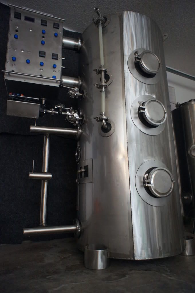
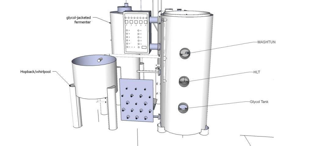
1. Three-tank-combi-tank. MT on top, HLT in middle, glycol tank on bottom.
Looking down into the Mash tun from the top through a cutaway into the HLT...
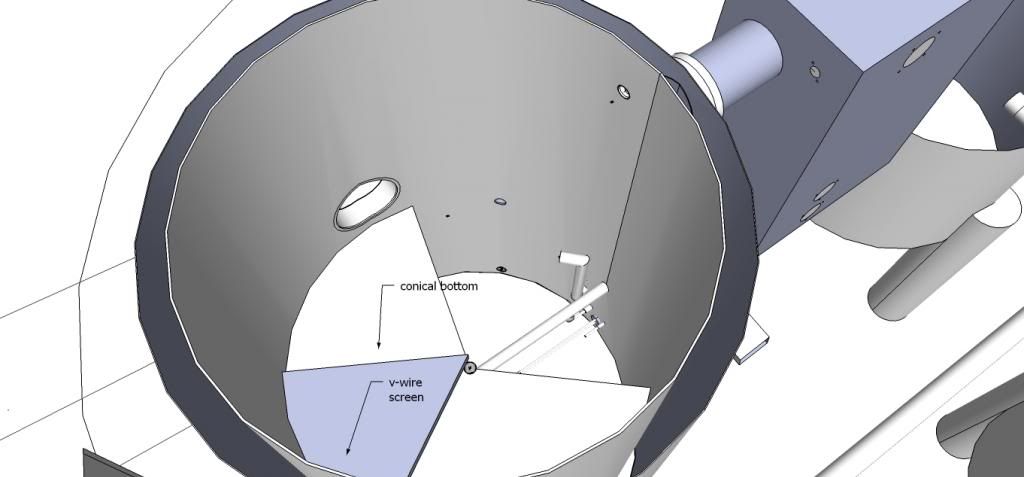
Looking further down into the HLT at the HLT float switch, electric heater element, and temp probe...
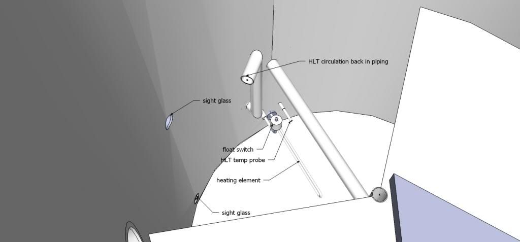
Looking into the HLT from the front...

2. Separate gas boil kettle, whirlpool/hopback, fermenter.
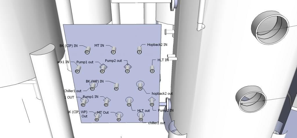
3. Wort/Hot water Flow Control Panel...
4. Electric control panel...
The control Panel.
Auberins 2342 PIDs,
Auberins ASL-51 timer
50 amp SSR for HLT
Switches, indicator lights, indicator buzzer, and various necessary control panel internals.
The control panel will control:
*** two Little Giant 3-md-hc pumps (on the back of the liquid flow panel) that can shuttle wort, hot water, hot wort, CIP cleaner in and out of any piece of equipment.
*** one 5500 watt heating element in HLT
*** one centrifugal pump for circulating glycol in a cooling tank
*** three solenoid valves for directing glycol either to fermenter or to circulate in cooling tank.
*** one 10,000 BTU compressing unit for chilling glycol.
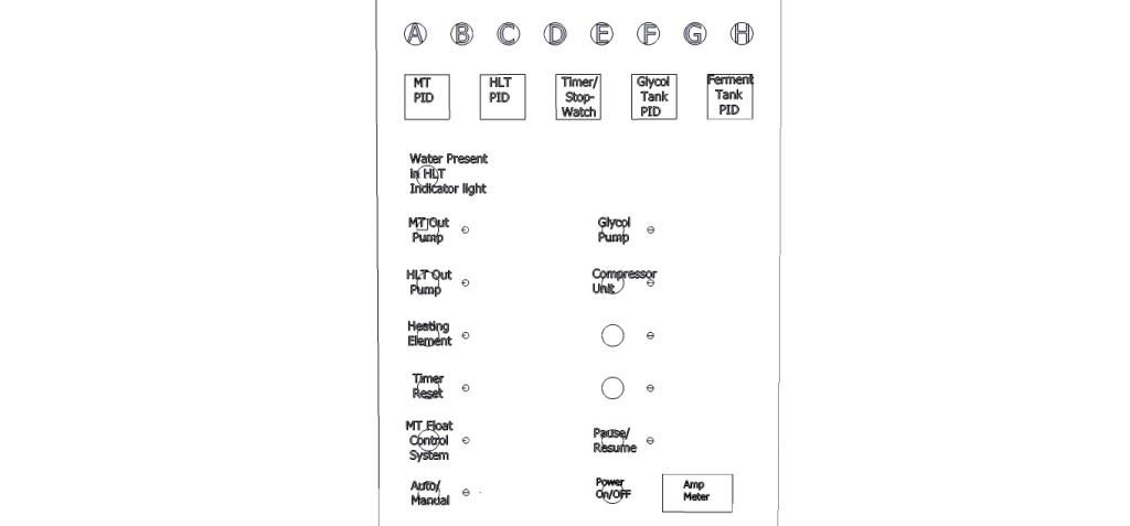
What I'd like for my control panel is seen below, with all the LOGIC steps below that.
Looking at the above picture, to begin the brew day, I'd start off pressing Main Power on. Then press button A (Operate Water tank). The HLT Pid would turn on allowing me to set i to a strike in temperature. An indicator light next to the automatic start vs manual start button would light up suggesting a response. If automatic start is selected, then the timer would allow a countdown to when the entire process starts heating water. Indicator lights next to the HLT out pump will light up suggesting a response. It must be depressed before pump would turn on at the countdown time. The HLT float would prohibit pumps and element to be on if there is no water in the HLT. Pause/Resume indicator light suggesting the pause/resume button can be used to pause pumps and element is enabled... ALL OTHER INDICATOR LIGHTS WILL BE OFF AND THEIR ADJACENT BUTTONS WOULD BE DISABLED. All of this is seen in the outline below... I hope it makes sense... Just want to know if a Click PLC can do all of this for my system...
[ ] = Latching Button
( ) = Momentary Button
{ } = Device
I. [Main Power]
A) (OPERATE WATER TANK)
***arrange piping for***
MT → HLT → HLT out Pump → MT (uni-tank circulation)
i. {HLT PID} turns on
(a) Set HLT strike-in temp to 163 F
ii. {Timer/stopwatch} turns on
(a) Set timer to countdown to begin heating water process at 5:00 AM
iii. {Indicator light} next to [automatic/manual start switch] lights up
(a) Set for automatic or manual start to heat water.
iv. {Indicator light} next to [HLT Out Pump switch] lights up
(a) Set pump ON to begin circulating when process begins.
v. {HLT float} activates & senses if water is or is not present
(a) Water sensed in HLT.
vi. {Indicator light} for Water Present in HLT lights up when water
vii. {Indicator light} next to [Pause/Resume switch] lights up
(a) Allows pause/resume during heating of water tank.
LOGIC for OPERATE WATER TANK:
IF A True, THEN latch A & unlatch B, C, D, G, H
IF i-v True, THEN heating element fires on & off.
IF ii-v True, THEN HLT pump always on for recirculation.
IF vii True, THEN heating element & pump off.
B) (OPERATE MASH & HEAT SPARGE WATER)
***arrange piping for***
MT → MT out pump → MT circulation
HLT → HLT out pump → HLT circulation
i. {HLT PID} & {MT PID} turn on
(a) Set HLT to 168 to prep sparge water temperature.
(b) {MT PID} is just to observe MT temp, will not influence process.
ii. {Timer/Stopwatch} turns on
(a) Works only as a stopwatch to monitor length of mash process.
(b) Set to 60 minute (or length of mash process)
iii. {Indicator light} next to [MT OUT Pump switch] lights up
(a) Set MT OUT Pump switch to ON
(b) Arrange tubing for MT recirculation
iv. {Indicator light} next to [HLT OUT Pump switch] lights up
(a) Set HLT OUT Pump switch to ON
v. {HLT float} activates & senses if water is or is not present
(a) Water sensed in HLT.
vi. {Indicator light} for Water Present in HLT lights up when water
vii. {Indicator light} next to [Heating Element switch] lights up
(a) Set Heating Element Switch to ON
viii. {Indicator light} next to [Pause/Resume switch] lights up
LOGIC FOR OPERATE MASH & HEAT SPARGE WATER
IF B True, THEN Latch B & Unlatch A, C, D, G, H
IF iii True, THEN MT Pump ON
IF iv True, THEN HLT Pump ON
IF i, iv, v, & vii, True THEN Heating Element fires On/Off
If viii True THEN All pumps & heating element OFF.
C) (OPERATE SPARGE AND DRAIN WORT)
***arrange piping for***
MT → MT out pump → Boil Kettle
HLT → HLT out pump → MT
i. {HLT PID} & {MT PID} turn on.
1. {MT PID} controls {heating element}
2. {MT PID} monitors sparge water temperature at the point in the piping just before sparge water enters MT.
3. {HLT PID} just to observe the temperature in the HLT.
ii. {Timer/Stopwatch} turns on.
1. Works only as stopwatch to monitor 60 minute fly-sparge
iii. {Indicator light} next to [MT OUT Pump switch] lights up
1. turn ON to power pump
iv. {Indicator light} next to [HLT OUT Pump switch] lights up
1. Turn ON to power pump to begin sparge process.
2. Throttle back valve on pump to a manageable sparge rate.
v. {Indicator light} next to [MT float control system switch] lights up
1. Turn ON [MT float control system]
(a) IF MT float is in low position, then it temporarily stops {MT OUT pump} to allow constant flow rate of hot water from HLT to fill MT.
(b) IF MT float is in high position, then it starts {MT OUT pump} to drain wort into Boil Kettle.
vi. {Indicator light} for Water Present in HLT lights up when water
vii. {Indicator light} next to [heating element switch] lights up
1. Turn ON
viii. Pause/Stop
1. Turn ON
LOGIC FOR OPERATE SPARGE AND DRAIN WORT
IF C True, THEN Latch C & Unlatch A, B, D, G, H
IF iv True, THEN HLT Sparge Pump ON
IF iii, v(1), v(1)(b) True THEN MT Drain Pump ON
IF i, iv, vi, vii True THEN Heating element fires ON/OFF
If viii, THEN All pumps and heating element OFF
D) Chill Wort /begin heating HLT water for cleanup observe chiller-out temps, hop back temps, bk temps, cooling water temp through manual temperature guages, not PIDs.
***Orient pipes BK → whirlpool → Chiller → whirlpool
i. MT out pump & HLT out pump connected to chiller and whirlpool at flow control panel
ii. {Indicator light} next to [MT OUT Pump switch] lights up
1. turn ON to power pump to pump hot wort out of whirlpool through chiller #1 back into whirlpool.
iii. {Indicator light} next to [HLT OUT Pump switch] lights up
1. Turn ON to power pump to pump hot wort out of whirlpool through chiller #2 back into whirlpool.
iv. {HLT PID} turn on.
1. {HLT PID} controls {heating element}
v. {Indicator light} for Water Present in HLT lights up when water
vi. {Indicator light} next to [heating element switch] lights up
1. Turn ON
vii. Pause/Stop
LOGIC FOR CHILL WORT/begin heating CIP water
IF D True, THEN Latch D & Unlatch A, B, C, G, H
IF ii True, THEN MT Out pump turns ON
IF iii True, THEN HLT Out pump turns ON
IF iv, v, vi, True THEN Heating element fires ON/OFF
If vii, THEN All pumps and heating element OFF
E) Chill Glycol Tank
i. {Glycol Tank PID} turns on
1. {Glycol Tank PID} controls {glycol compressor unit}
(a) set Glycol Tank PID to 25 degrees F.
ii. {Indicator light} next to [Glycol Pump] lights up
1. turn ON to power pump to circulate glycol from bottom of tank to top of tank (condensing unit cooling coils found inside tank)
iii. {Indicator light} next to [pause/resume] lights up
LOGIC FOR CHILL GLYCOL TANK
IF E True, THEN Latch E & Unlatch F
IF ii True, THEN Glycol Pump ON
IF i and ii True, THEN Compressor unit ON
IF iii True, THEN Pumps & Compressor OFF
F) Chill Fermentation Tank
i. {Glycol Tank PID} and {Fermenter PID} turn on
1. {Glycol Tank PID} controls {glycol compressor unit}
(a) set Glycol Tank PID to 25 degrees F.
2. {Fermenter PID} controls glycol pump and two solenoid valves that redirect glycol to fermenter.
(a) Set Fermenter PID to 65 degrees F.
ii. {Indicator light} next to [Glycol Pump] lights up
1. turn ON to power pump to direct glycol from bottom of tank
iii. {Indicator light} next to [pause/resume] lights up
LOGIC FOR CHILL GLYCOL TANK
IF F True, THEN Latch F & Unlatch E
IF i(1.) and ii True, THEN Compressor and pump ON
IF i(2.) and ii True, THEN Compressor unit, pump, both solenoids ON.
IF iii True, THEN Pumps, solenoids & Compressor OFF
G) CIP
i. All PIDs on Timer ON
ii. PID and Pump auto for HLT heating, Timer maybe for clean for a certain duration
iii.
H) Observe
i. All PIDs On
ii. Timer on as stopwatch.
II. POWER OFF
******************* SO MY BIG QUESTION is will a Click PLC do all of this? What's my next step?
First though, a background on the equipment:
1. Three-tank-combi-tank. MT on top, HLT in middle, glycol tank on bottom.


Looking down into the Mash tun from the top through a cutaway into the HLT...

Looking further down into the HLT at the HLT float switch, electric heater element, and temp probe...

Looking into the HLT from the front...

2. Separate gas boil kettle, whirlpool/hopback, fermenter.
3. Wort/Hot water Flow Control Panel...

4. Electric control panel...

The control Panel.
Auberins 2342 PIDs,
Auberins ASL-51 timer
50 amp SSR for HLT
Switches, indicator lights, indicator buzzer, and various necessary control panel internals.
The control panel will control:
*** two Little Giant 3-md-hc pumps (on the back of the liquid flow panel) that can shuttle wort, hot water, hot wort, CIP cleaner in and out of any piece of equipment.
*** one 5500 watt heating element in HLT
*** one centrifugal pump for circulating glycol in a cooling tank
*** three solenoid valves for directing glycol either to fermenter or to circulate in cooling tank.
*** one 10,000 BTU compressing unit for chilling glycol.
What I'd like for my control panel is seen below, with all the LOGIC steps below that.
Looking at the above picture, to begin the brew day, I'd start off pressing Main Power on. Then press button A (Operate Water tank). The HLT Pid would turn on allowing me to set i to a strike in temperature. An indicator light next to the automatic start vs manual start button would light up suggesting a response. If automatic start is selected, then the timer would allow a countdown to when the entire process starts heating water. Indicator lights next to the HLT out pump will light up suggesting a response. It must be depressed before pump would turn on at the countdown time. The HLT float would prohibit pumps and element to be on if there is no water in the HLT. Pause/Resume indicator light suggesting the pause/resume button can be used to pause pumps and element is enabled... ALL OTHER INDICATOR LIGHTS WILL BE OFF AND THEIR ADJACENT BUTTONS WOULD BE DISABLED. All of this is seen in the outline below... I hope it makes sense... Just want to know if a Click PLC can do all of this for my system...
[ ] = Latching Button
( ) = Momentary Button
{ } = Device
I. [Main Power]
A) (OPERATE WATER TANK)
***arrange piping for***
MT → HLT → HLT out Pump → MT (uni-tank circulation)
i. {HLT PID} turns on
(a) Set HLT strike-in temp to 163 F
ii. {Timer/stopwatch} turns on
(a) Set timer to countdown to begin heating water process at 5:00 AM
iii. {Indicator light} next to [automatic/manual start switch] lights up
(a) Set for automatic or manual start to heat water.
iv. {Indicator light} next to [HLT Out Pump switch] lights up
(a) Set pump ON to begin circulating when process begins.
v. {HLT float} activates & senses if water is or is not present
(a) Water sensed in HLT.
vi. {Indicator light} for Water Present in HLT lights up when water
vii. {Indicator light} next to [Pause/Resume switch] lights up
(a) Allows pause/resume during heating of water tank.
LOGIC for OPERATE WATER TANK:
IF A True, THEN latch A & unlatch B, C, D, G, H
IF i-v True, THEN heating element fires on & off.
IF ii-v True, THEN HLT pump always on for recirculation.
IF vii True, THEN heating element & pump off.
B) (OPERATE MASH & HEAT SPARGE WATER)
***arrange piping for***
MT → MT out pump → MT circulation
HLT → HLT out pump → HLT circulation
i. {HLT PID} & {MT PID} turn on
(a) Set HLT to 168 to prep sparge water temperature.
(b) {MT PID} is just to observe MT temp, will not influence process.
ii. {Timer/Stopwatch} turns on
(a) Works only as a stopwatch to monitor length of mash process.
(b) Set to 60 minute (or length of mash process)
iii. {Indicator light} next to [MT OUT Pump switch] lights up
(a) Set MT OUT Pump switch to ON
(b) Arrange tubing for MT recirculation
iv. {Indicator light} next to [HLT OUT Pump switch] lights up
(a) Set HLT OUT Pump switch to ON
v. {HLT float} activates & senses if water is or is not present
(a) Water sensed in HLT.
vi. {Indicator light} for Water Present in HLT lights up when water
vii. {Indicator light} next to [Heating Element switch] lights up
(a) Set Heating Element Switch to ON
viii. {Indicator light} next to [Pause/Resume switch] lights up
LOGIC FOR OPERATE MASH & HEAT SPARGE WATER
IF B True, THEN Latch B & Unlatch A, C, D, G, H
IF iii True, THEN MT Pump ON
IF iv True, THEN HLT Pump ON
IF i, iv, v, & vii, True THEN Heating Element fires On/Off
If viii True THEN All pumps & heating element OFF.
C) (OPERATE SPARGE AND DRAIN WORT)
***arrange piping for***
MT → MT out pump → Boil Kettle
HLT → HLT out pump → MT
i. {HLT PID} & {MT PID} turn on.
1. {MT PID} controls {heating element}
2. {MT PID} monitors sparge water temperature at the point in the piping just before sparge water enters MT.
3. {HLT PID} just to observe the temperature in the HLT.
ii. {Timer/Stopwatch} turns on.
1. Works only as stopwatch to monitor 60 minute fly-sparge
iii. {Indicator light} next to [MT OUT Pump switch] lights up
1. turn ON to power pump
iv. {Indicator light} next to [HLT OUT Pump switch] lights up
1. Turn ON to power pump to begin sparge process.
2. Throttle back valve on pump to a manageable sparge rate.
v. {Indicator light} next to [MT float control system switch] lights up
1. Turn ON [MT float control system]
(a) IF MT float is in low position, then it temporarily stops {MT OUT pump} to allow constant flow rate of hot water from HLT to fill MT.
(b) IF MT float is in high position, then it starts {MT OUT pump} to drain wort into Boil Kettle.
vi. {Indicator light} for Water Present in HLT lights up when water
vii. {Indicator light} next to [heating element switch] lights up
1. Turn ON
viii. Pause/Stop
1. Turn ON
LOGIC FOR OPERATE SPARGE AND DRAIN WORT
IF C True, THEN Latch C & Unlatch A, B, D, G, H
IF iv True, THEN HLT Sparge Pump ON
IF iii, v(1), v(1)(b) True THEN MT Drain Pump ON
IF i, iv, vi, vii True THEN Heating element fires ON/OFF
If viii, THEN All pumps and heating element OFF
D) Chill Wort /begin heating HLT water for cleanup observe chiller-out temps, hop back temps, bk temps, cooling water temp through manual temperature guages, not PIDs.
***Orient pipes BK → whirlpool → Chiller → whirlpool
i. MT out pump & HLT out pump connected to chiller and whirlpool at flow control panel
ii. {Indicator light} next to [MT OUT Pump switch] lights up
1. turn ON to power pump to pump hot wort out of whirlpool through chiller #1 back into whirlpool.
iii. {Indicator light} next to [HLT OUT Pump switch] lights up
1. Turn ON to power pump to pump hot wort out of whirlpool through chiller #2 back into whirlpool.
iv. {HLT PID} turn on.
1. {HLT PID} controls {heating element}
v. {Indicator light} for Water Present in HLT lights up when water
vi. {Indicator light} next to [heating element switch] lights up
1. Turn ON
vii. Pause/Stop
LOGIC FOR CHILL WORT/begin heating CIP water
IF D True, THEN Latch D & Unlatch A, B, C, G, H
IF ii True, THEN MT Out pump turns ON
IF iii True, THEN HLT Out pump turns ON
IF iv, v, vi, True THEN Heating element fires ON/OFF
If vii, THEN All pumps and heating element OFF
E) Chill Glycol Tank
i. {Glycol Tank PID} turns on
1. {Glycol Tank PID} controls {glycol compressor unit}
(a) set Glycol Tank PID to 25 degrees F.
ii. {Indicator light} next to [Glycol Pump] lights up
1. turn ON to power pump to circulate glycol from bottom of tank to top of tank (condensing unit cooling coils found inside tank)
iii. {Indicator light} next to [pause/resume] lights up
LOGIC FOR CHILL GLYCOL TANK
IF E True, THEN Latch E & Unlatch F
IF ii True, THEN Glycol Pump ON
IF i and ii True, THEN Compressor unit ON
IF iii True, THEN Pumps & Compressor OFF
F) Chill Fermentation Tank
i. {Glycol Tank PID} and {Fermenter PID} turn on
1. {Glycol Tank PID} controls {glycol compressor unit}
(a) set Glycol Tank PID to 25 degrees F.
2. {Fermenter PID} controls glycol pump and two solenoid valves that redirect glycol to fermenter.
(a) Set Fermenter PID to 65 degrees F.
ii. {Indicator light} next to [Glycol Pump] lights up
1. turn ON to power pump to direct glycol from bottom of tank
iii. {Indicator light} next to [pause/resume] lights up
LOGIC FOR CHILL GLYCOL TANK
IF F True, THEN Latch F & Unlatch E
IF i(1.) and ii True, THEN Compressor and pump ON
IF i(2.) and ii True, THEN Compressor unit, pump, both solenoids ON.
IF iii True, THEN Pumps, solenoids & Compressor OFF
G) CIP
i. All PIDs on Timer ON
ii. PID and Pump auto for HLT heating, Timer maybe for clean for a certain duration
iii.
H) Observe
i. All PIDs On
ii. Timer on as stopwatch.
II. POWER OFF
******************* SO MY BIG QUESTION is will a Click PLC do all of this? What's my next step?

