BruControl: Brewery control & automation software

Homebrew Talk - Beer, Wine, Mead, & Cider Brewing Discussion Forum

Help Support Homebrew Talk - Beer, Wine, Mead, & Cider Brewing Discussion Forum:

This site may earn a commission from merchant affiliate links, including eBay, Amazon, and others.
Can something like a Glycol Pump be a Hysteresis element?

From my testing, any output can be driven by a hysteresis element. Just keep in mind that you can't have the pump digital output element enabled at the same time as when it's under hysteresis control.
 
Thanks. The pump will only be used to cool the fermentor. When I had it set up with the BCS, I had a 1 degree F swing that seemed to work. I am likely getting a Spike CF 30 with a cooling coil so it may be different. I have a Brewers Hardware on order since February and may give up on it
 
I’m still not fully tracking you. I don’t know what you mean about going on long walkabouts…

Bottom line is if the application loses communication with the interface, the interface will hold its mode. When the communication restores, the interface will be updated with any changes that were made in application in the interim.

If an interface loses power, it will of course lose its state but it will get restored immediately upon reconnection with the application. If you lose both power to the interface AND communication permanently, then of course the interface modes won’t be updated. This is where a LiPo battery can help. And of course, for fermentation, if you lose power, your cooling won’t be happening anyway, unless you have a generator or beefy UPS backup.

It’s not possible (nor practical In a homebrewing application) to make it 100% hardened against failure. Even if you get the application, communication, and power right, there is always a gremlin ready to mess your **** up. Glycol can take on water and freeze, a compressor can fail, etc.

Hysteresis and other device elements don’t know (or care) what they are connected to - so you can certainly use it to run a pump.
 
Long walkabouts: I am going to Durango Co for two weeks at Christmas. I am going to Egypt for 5 weeks begining Feb 4. After I get back, I am going to take my grandchildren skiing again in Durango for a week. I am out of town on a regular basis for weeks.

I am not worried about a hard system, I just like the fact that the interface will continue.

We do have power outages (I am slightly rural), but power is normally restored quickly (I am on the same part of the grid as our local emegency services).

Unfortunately, power outages do cause connection and reconnection issues with my routers and extenders. About 1 time in 5, I totally loose my internet and have to manually reset a breaker in their box (the technician showed me how as it takes days to get them to come and flip a switch) when I loose power.

I was just curious as to what will happen. Not asking for anything to be done, but just to better understand the benefits and limitaions (and planning for backup procedurures like a diacytel rest on a lager if I lose a timer).

When I had the BCS, I used bistable relays as Digital Inputs where I set them when I started the rest, when the rest started, when the rest finished, and where the lager temp was reached. That way, if I was away, the rest might take up apx where it was. I am planning on using Globals for those logics.

That is the reason I requested the date diff function. I might want to reset a timer based on the date diff if I lost power to my BruControl computer. I do have UPS and Lipo for my system but not for all the routers.
 
On the topic of network connection vs dongle, one issue I have thought about is if BruControl decides to call it quits. Would we be out the money and all of the time we have put into the solution? This is where a dongle might be preferred until we could move to another solution. They could also leave the license server up for a while as well, but that would not be in my control, understanding we would not get any more development or changes. Something to think about.
 
So its just like any other software that has been written, licensed, and sold... ever?

Sorry for the tongue in cheek, but my point is what is your expectation? No software life cycle lasts forever. From the licensing side, having spent a good portion of my career removing hardware keys/dongles from industrial environments due to *cough* reliability issues *cough*, its my opinion that they are at best a band-aid and at worst a production stopper. Could they work in the event that BrunDog is done with the project, maybe, but it would be far easier to simply issue a perpetual software license key from the license server that is already running.
My point is this software has to have a connection to a server every 30 days, then become unusable if it does not. if I want to use the same version of office for 10 years I can.
 
I was in the same with customers. I had some pay phone software that I had written and had software license key and my clients were worried about it, Like most things, it was eventually killed by me for the one or two clients still using it as the pay phone industry was dead except in Jails (mostly federal) and Colorado (you have to have a payphone at a gas station for 24/7 operations without an antendent). I did give those still using a perpetual software license key. We all know of Brewing Projects that have died on the vine. With a vibrant comunity, maybe an open source if @BrunDog ever quits!

Beyond a doubt, this is the best brewing software available as it allows you to control the flow. I am sure the big brewers have excellent $$$ software, but a logic change might require a visit (at $$$) from a software engineer where we can effect it with a Script Change!
 
Good discussion. We honestly have thought about the situation for if we were to cease supporting it. First off, ain’t gonna happen for the foreseeable future. We have a functional contract with our users and have every intention on holding up our end of that deal. Second, the easy solution would be to keep the license server running, for several years which we would commit to doing.

That said, I’m sure everyone is wondering where the latest updates are. The truth is my developer partner has had so many busy life events (young family etc) that he hasn’t been able to dedicate the time needed to get updates done recently, so we are bringing in another developer partner. He’s reviewed the code and we hope to get at least a minor update out very soon.
 
Any one using the Pressure Sensor? I have ordered a 50 gal Spike BK to use as an Electric HLT. I had a Sensor port added and am thinking of getting the 100 mb Pressure Sensor for Stike and Sparge transfers.
 
I use volume sensors and they work fine, however my preference and opinion is that a flow meter is more accurate for vessel to vessel transfers.
 
That’s probably true… I personally love having the real-time display of the volume. I’ve had good success with volume though do admit they vary a bit with increasing temperature. I use it on my personal rig for electronic auto-sparging. Fly-sparge water in is checked for flow to achieve 1 qpm, then the MT volume is watched - if it creeps up, the proportional valve to the BK is opened a tad, if it creeps down, the valve to the BK is closed a tad.
 
For sure real time feedback is great, and making it actionable is even better. For example, I have found it useful to leverage the level sensors as an interlock check of sorts with the flow meter to make sure a vessel is filled to a certain amount before enabling a heating element, greatly reducing the chances of a dry fire.
 
I do not need to be super acurate, When we brew, we use a dowel stick with 1 gal marks on it for the strike. For Batch Sparge we use the TLAR method. We just add water to when the grain bed looks like it is floating. We use a sight gauge on the brew kettle for that volume. I have both flow meters and the pressure port so I will have both once I get the preesure sensor. I have also thought about load sensors. The load sensor for the Mash Tun. The pressure sensor on the electric HLT. My Mash Tun has no heating (Modified HERMS heating for the wort). That way we can leave the stick on the wall and be more repeatable. I gave up on Brewers Hardware getting my HLT and ordered one from Spike.
 
I love BruControl, I really do... but again, somehow at 3am, the damn windows pc that was set to 'notify to install, notify to restart' via gpedit.msc actually restarted due to an update and my ferment overshot temp by ten degrees........ and I cannot have it run on hysteresis because my mega controls the chiller and an ESP32 controls the Tilt temps and the RTD's. whenever I connect an RTD to my mega (which has spi ethernet), the mega locks up, as I have posted a few times...
1636553910367.png
 
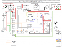
After integrating Brucontrol into my current setup (fermenters with glycol cooling) and reading this entire thread (OK, I skipped a few pages and skimmed a lot), I am contemplating building a new system from scratch and am looking for some design ideas/plans. I would like to build an automated RIMS based system for 5gal batches. I have a 30amp service already, so would like to stick with that if possible. I would also like CIP. Does anyone have a plumbing diagram of a model system that I can use as a starting point? Typically, I do a piss-poor job of planning and end up regretting it, so this time I am going to try to plan everything before I start spending money.
 
After integrating Brucontrol into my current setup (fermenters with glycol cooling) and reading this entire thread (OK, I skipped a few pages and skimmed a lot), I am contemplating building a new system from scratch and am looking for some design ideas/plans. I would like to build an automated RIMS based system for 5gal batches. I have a 30amp service already, so would like to stick with that if possible. I would also like CIP. Does anyone have a plumbing diagram of a model system that I can use as a starting point? Typically, I do a piss-poor job of planning and end up regretting it, so this time I am going to try to plan everything before I start spending money.
I just updated my post with new control panel and plumbing diagrams for a 30A RIMS setup with CIP. The electrical wiring assumes using the ProductivityOpen hardware (which is hopefully coming soon to BruControl, fingers crossed) but you should be able to merge in the Grand Central wiring from my older diagram.
 
I just updated my post with new control panel and plumbing diagrams for a 30A RIMS setup with CIP. The electrical wiring assumes using the ProductivityOpen hardware (which is hopefully coming soon to BruControl, fingers crossed) but you should be able to merge in the Grand Central wiring from my older diagram.
This is great, thanks.
 
I've got a strange problem that I think may be a grounding issue. Each time I turn off something that is using 240V (i.e. pump) my PC monitor (same circuit) briefly turns off then on, as does BruControl. All my temp sensors reset etc. I've followed the recommended wiring in the BruControl website with a couple of small changes (nothing major). Any ideas what could be causing this/ how to fix it?
 
This seems like a great system, especially like the Uniflex and how it can be configured. I have a desktop computer but think an all-in-one or laptop would be more appropriate as having the computer in another room controlling the brewing system over wi-fi, while possible, is probably not wise. Are there minimum computer specs for the BruControl software such that it runs smooth, doesn't feel bogged down or laggy, etc...? (i.e. both the editor and the created control panel)
 
Last edited:
Finally getting close to building my first controller and looking for input. I had little to no clue how to a) read a schematic or b) use draw.io so excuse the primitive design. I realize some of my wire colors and size may be off slightly but at this point I'm mostly just trying to make sure I have my connections right.

This build is a 240/30A setup with a proportional SSR for a single 5500w element (HLT/BK) and an AC Dimmer for a PWM Mark II pump. At this point I haven't specified the pins on the ESP32, that's next as soon as I can find a stencil.
 

Attachments

Thanks I'll look into this. Any recommendations for varistor (MOV) values, and do I need to change the R/C values for 240V?
Would need more motor information before a recommendation could be made. Motor voltage (240v), max current draw, frequency. I'm using Quencharc RC snubbers on 120v pumps with good success.
 

Attachments

  • Quencharc_QRL.pdf
    177.8 KB · Views: 17
Last edited:
Finally getting close to building my first controller and looking for input. I had little to no clue how to a) read a schematic or b) use draw.io so excuse the primitive design. I realize some of my wire colors and size may be off slightly but at this point I'm mostly just trying to make sure I have my connections right.

This build is a 240/30A setup with a proportional SSR for a single 5500w element (HLT/BK) and an AC Dimmer for a PWM Mark II pump. At this point I haven't specified the pins on the ESP32, that's next as soon as I can find a stencil.

Overall looks pretty good, but some notes below:
  • All of your relay connections should be moved to the normally open contact so that their default state is off and they will fail open rather than closed.
  • Looks like you're missing the AC connections to power the 5V and 12V power supplies.
  • You're PWM/Analog AOut and AGND should be swapped; you want the ground to connect to the side of the diode icon with the bar; think of current flowing from + to - in the direction of the triangle.
  • Should the ACLoad- and ACIn- of the PWM Dimmer be tied together? I've never used one before so I'm not sure but something you may want to double check on. It may need to be separated the way your + connections are.
  • The fuse in series with the red AC line is redundant as the other fuse will cover that loop of the circuit.
  • You'll want either a smaller amp breaker or fuses in line with the other AC lines that go out to the relays.
  • I know you said you still have to work on exact pins for the ESP32 but don't forget about power connection to the device.
 
Would be nice to have a none funtioning copy of the program that you could write scripts with and then transfer to the "working" PC. I travel and would like to be able to script while I am away (in some places with no or very bad internet so a remote connection would not work,)
 
Would be nice to have a none funtioning copy of the program that you could write scripts with and then transfer to the "working" PC. I travel and would like to be able to script while I am away (in some places with no or very bad internet so a remote connection would not work,)

You can do this now. An un-activated copy will still run scripts. You aren't connected to live hardware anyway, so activation isn't needed.
 
Overall looks pretty good, but some notes below:
  • All of your relay connections should be moved to the normally open contact so that their default state is off and they will fail open rather than closed.
  • Looks like you're missing the AC connections to power the 5V and 12V power supplies.
  • You're PWM/Analog AOut and AGND should be swapped; you want the ground to connect to the side of the diode icon with the bar; think of current flowing from + to - in the direction of the triangle.
  • Should the ACLoad- and ACIn- of the PWM Dimmer be tied together? I've never used one before so I'm not sure but something you may want to double check on. It may need to be separated the way your + connections are.
  • The fuse in series with the red AC line is redundant as the other fuse will cover that loop of the circuit.
  • You'll want either a smaller amp breaker or fuses in line with the other AC lines that go out to the relays.
  • I know you said you still have to work on exact pins for the ESP32 but don't forget about power connection to the device.

I'll add... what is the "Dimmer". It is not that easy to regulate AC at current... just make sure the part is suited for the application.
 
Overall looks pretty good, but some notes below:
  • All of your relay connections should be moved to the normally open contact so that their default state is off and they will fail open rather than closed.
  • Looks like you're missing the AC connections to power the 5V and 12V power supplies.
  • You're PWM/Analog AOut and AGND should be swapped; you want the ground to connect to the side of the diode icon with the bar; think of current flowing from + to - in the direction of the triangle.
  • Should the ACLoad- and ACIn- of the PWM Dimmer be tied together? I've never used one before so I'm not sure but something you may want to double check on. It may need to be separated the way your + connections are.
  • The fuse in series with the red AC line is redundant as the other fuse will cover that loop of the circuit.
  • You'll want either a smaller amp breaker or fuses in line with the other AC lines that go out to the relays.
  • I know you said you still have to work on exact pins for the ESP32 but don't forget about power connection to the device.

Thanks so much for taking the time to review my schematic.

I meant to have those relays be NO and I'll add those AC connections for the PS and the 5v for the ESP.

I'll have to check with others how they're wiring those dimmers...I thought both of those go to ground but could be wrong. This was in one of the reviews on the product page...

On the low voltage side you have your 5v/3.3v, ground, and PWM signal inputs, on the high voltage side you have an AC input and AC load, both with their respective lables (Live and Neutral).

To answer @BrunDog, these boards have been used to control mark II pumps successfully.

The extra fuse was something I just forgot to remove from the original schematic since I cut out the other pieces that deemed it necessary.

Thanks for the reminder on the other breaker...I think that got lost when I was trying to rearrange everything to make room for the relay board.
 
Last edited:
Trying to solve an issue with Thermistors. I use the TF-4 board connected to a 5VDC PS (not MEGA). The MEGA AREF is also connected to the 5VDC PS. I have 5 sensors (MF51E103E3950). After a period of time (weeks), the sensors become so inaccurate that they have to be replaced. I cannot figure out what is causing the sensors to fail. Any ideas for troubleshooting?
 
Trying to solve an issue with Thermistors. I use the TF-4 board connected to a 5VDC PS (not MEGA). The MEGA AREF is also connected to the 5VDC PS. I have 5 sensors (MF51E103E3950). After a period of time (weeks), the sensors become so inaccurate that they have to be replaced. I cannot figure out what is causing the sensors to fail. Any ideas for troubleshooting?

Hmmm. Makes no sense. Is everything grounded together? Any pictures you can share?

Also, the thermistors use basically no power... you can use the MEGA's power very safely.
 
Hmmm. Makes no sense. Is everything grounded together? Any pictures you can share?

Also, the thermistors use basically no power... you can use the MEGA's power very safely.

T-Block 100-105 5VDC
T-Block 1-10 5VDC/12VDC Ground
T-Block 20-29 12VDC

TF-4 power is T-Block 102 (+) and T-Block 9 (-)

T-Block 100 goes to MEGA AREF (purple wire)
 

Attachments

  • DC_Pic.jpg
    DC_Pic.jpg
    204.9 KB · Views: 22
Just received my Brucontrol Uniflex V2 (HUGE shoutout to @BrunDog ....I can already tell this system is going to totally rock!). I am outfitting a spike solo to be ~90% automated utilizing ~8 bidirectional 24V valves. Will post pics post-Uniflex integration :). Question for the group as I am getting setup....

Context: I am using an external 24V 100W power supply to lower current limits on the Uniflex V2 (vs. using the integrated 12V supplied by the Uniflex). I'm familiar with Brucontrol wiring as I custom built a fermentation controller with 10-15 different sensors+controllers but trying to understand the Uniflex v2 documentation for this initial setup....

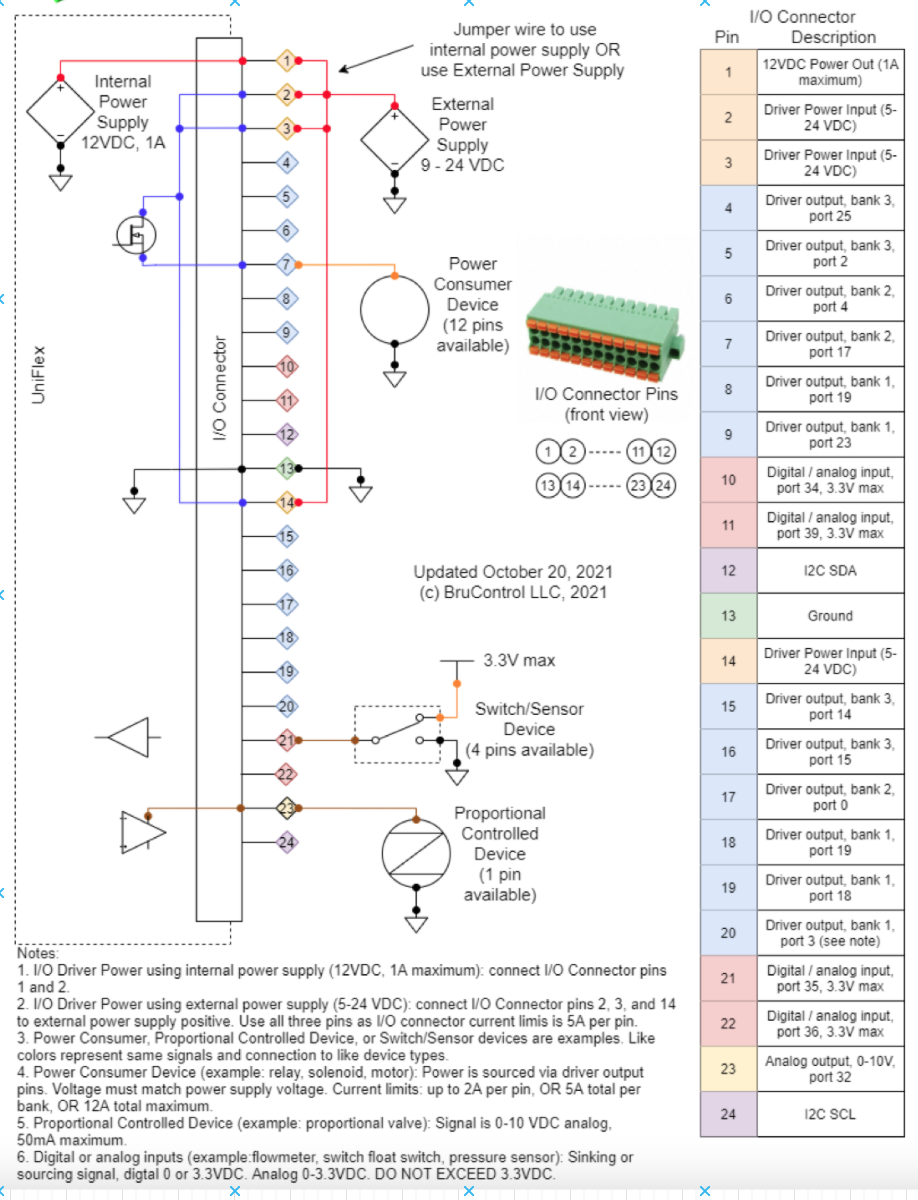
Question for the group on wiring an external PSU + my 8x 24V valves to the Uniflex v2: The Uniflex manual states"I/O Driver power using external power supply 5-24 VDC: Connect I/o Connector pins 2,3, and 14 to external power supply POSITIVE. Use all three pins as I/O connector current limits is 5A per pin". Based on this, can you please take a look at my wiring diagram (attached below) and let me know if I have the respective wiring correct for the PSU and 1x valve (as an example)? A few thoughts:
  • PSU ground does not appear to need wiring to the Uniflex...ONLY the positive line of the 24V PSU being wired to pins 2, 3, 14. Let me know if this is an incorrect assumption.
  • Not fully understanding why I need to provide 24V power to the uniflex as I was initially thinking I could wire the 24V PSU directly to the valves via DIN terminal block and only use the digital output pins of the Uniflex wired to the VALVE driver wire (1-wire) for the valves. In this situation I was planning to wire valve + and - direct to the 24V PSU without connecting the PSU to the Uniflex. Again, not following why I need to wire the 24V PSU to the Uniflex...
  • All 8 valves are CR3 03 wiring configuration if this is necessary for context (CR3 03 diagram here)
Also providing a screenshot with context of the Uniflex V2 schematic with footnotes.

Any help would be greatly appreciated so I can get running with my first brew :)

Thank you!

Screen Shot 2021-11-26 at 12.44.56 PM.png


Screen Shot 2021-11-26 at 12.45.14 PM.png
 
Back
Top