BruControl: Brewery control & automation software

Homebrew Talk - Beer, Wine, Mead, & Cider Brewing Discussion Forum

Help Support Homebrew Talk - Beer, Wine, Mead, & Cider Brewing Discussion Forum:

This site may earn a commission from merchant affiliate links, including eBay, Amazon, and others.
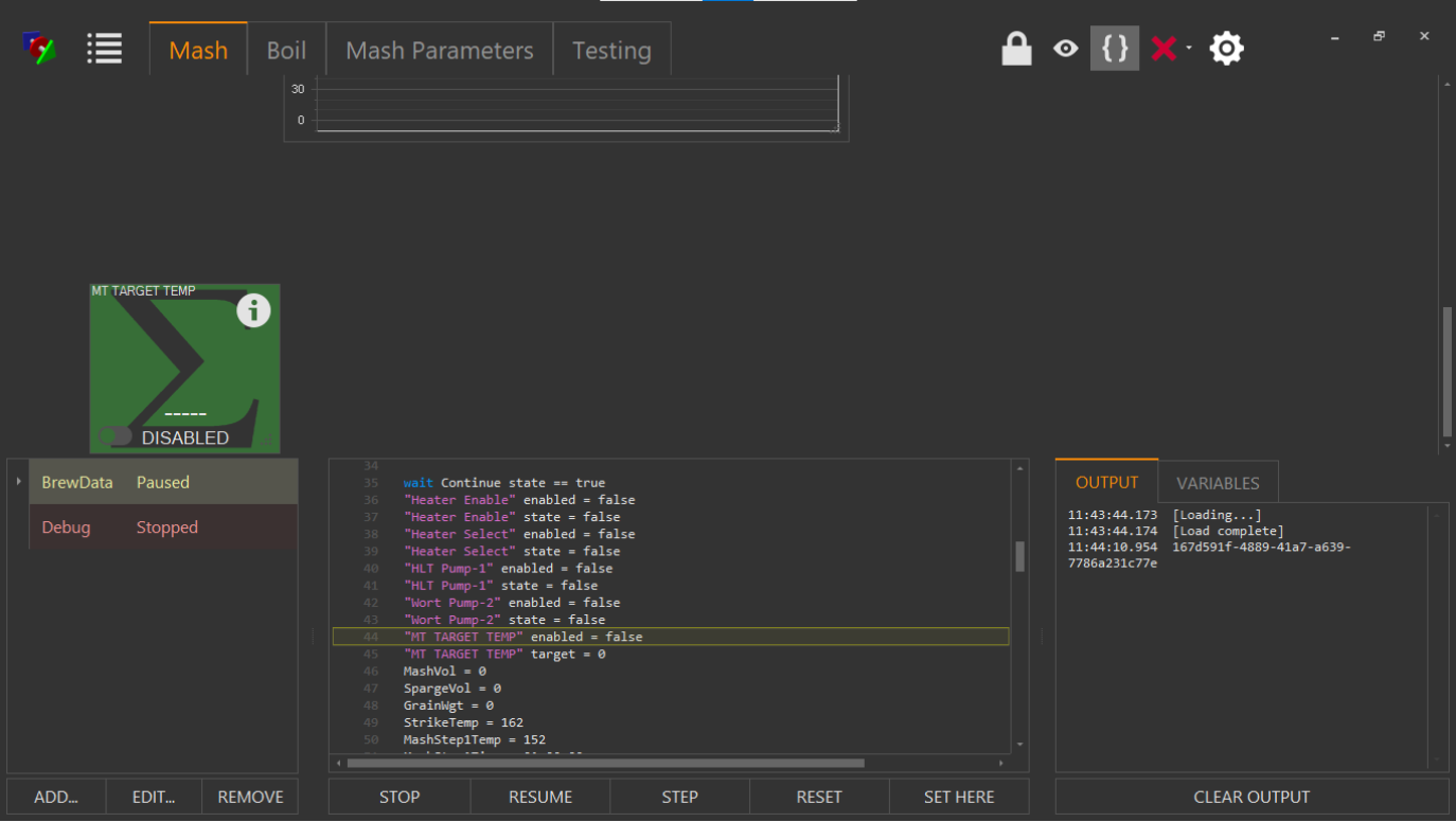
Plan on brewing on Sunday but will be entirely manual (no scripts - still working on that). A couple comments on added features:
  • Love the ability to enable/disable elements directly from the workspace
  • The new line code (...\n...) for strings now works as documented
 
Started a build on a 50A control system, which will be called the UniCon. This control enclosure will be the "standard" type box and will include a bunch of automation capability including lots of digital I/O, analog inputs, analog outputs, etc. Its control foundation will be a UniShield, and will show how it can be leveraged using universal connectivity to accommodate a user's expansion into more automation over time.

This build will be documented in a video series along the way. Here is the first video in this series. Happy to take any comments and questions as this is built!


I've been working through my schematic of the build based on the template supplied by Brucontrol and while most of the elements are on the template, I was wondering if you have a "library" of design elements you could supply like the UniShield UM-1 and the 8-pin aviation connectors that you use in your sample. I'm not that great at graphics and none of the libraries I found had these elements available. Since this is a "must do" it would be extremely helpful to have an element with the correct pin labels available in designing this. So far, I have been unable to change the pin labels on the Mega 2560 element you supplied. Perhaps there is a trick to this I need to discover? Thanks in advance.
 
Here is a little script for those using 1-wire sensors, and need to reset the bus for some reason (e.g. un-plug and re-plug). This script leverages the new direct command 'tx'. This script disables a 1-wire sensor, pauses resets the bus, pauses, then enables the sensor. Adjust names as needed if you use this.

Code:
"Temp 1" enabled = false
sleep 1000
tx "Interface" "%3"
sleep 1000
"Temp 1" enabled = true
stop "Script 1"
 
Is there a script property for the new appearance attribute "Display Name" ?

In fact is there any documentation for:
Added: Automatic Lock
Added: Direct script command
Added: Switch to disable log files (default)
Added: String text line feed
Added: Element Display Name (alias) field
Added: Script running status available in another script
Added: Dual Throw output (pending FW 45K)
Added: Device Element Enable Switch
Added: Choice of 3 or no Alarm sounds, plus script control
Added: Element location and size in properties
Added: Use PWM (if available) in PID and Deadband (pending FW 45K)
Added: Direct command (to interface) via script
Added: Script window height in settings

What I am looking for is any script commands or a practical explanation, if you have one.
 
We'll publish the updated manual when v1.2 is formally released. I think many of these are probably self explanatory but I'm happy to detail any until then.

But yes. The property is 'displayname', as shocking as that likely isn't.

Code:
new string text
text = "Temp 1" displayname
print text
sleep 1000
stop "Script 20"

Edit: Also, using this property, you can create an attention-getter at the element level. For example:

Code:
[loop]
"Temp 1" displayname = "Watch me"
sleep 1000
"Temp 1" displayname = "CLOSELY!"
sleep 1000
goto loop
stop "Script 20"

ezgif.com-video-to-gif.gif
 
Last edited:
Request 1: Lock on the Position and size of an Element that is tied to an attribute of the Element: Cannot resize or move Element if locked on the Element even when the Application is unlocked. I want to set the size and location and NOT be able to change it without unlocking the Element itself.

Request 2: I personally would not use and would not want the Enable Slide Switch on any Element. I control the Element "Enable" via script and would NOT want to be able to change on the fly. It is a Safety Issue for me as I have people "helping" Brew and I do not want them to be able to Enable anything on a Screen at anytime. When Brewing, the Workspace Lock Icon is "On" so no one can manipulate and Element unless I have it enabled. With this new feature, someone could dry fire an Element very easily but being six fingered (of which I am Guilty). Maybe another property of "Enable Switch Visible" as an attribute of an Element. A Global Setting to not display the Enable Switch in Settings would work for me.

Sorry... I'm not following #1.

For #2, the enable switch is controllable via that Element's settings. You can control whether it is visible always, never, or aligned with User Control.
 
Sorry... I'm not following #1.

For #2, the enable switch is controllable via that Element's settings. You can control whether it is visible always, never, or aligned with User Control.
#1

I have several places where I stack Elements on Top of One Another and use the Visibility as to which one is displayed in that specific area of a workspace.

For example, I have a Timer Element and a Global Element in the Upper Right of my Workspace. They are the same size and position. Depending on what is happening, I switch between the Global Element or the Timer Element being displayed.

The issue is that sometimes the Elements seem to move or resize on their own (I am sure I am doing something that causes the move and I think when I resize the script Window is when I notice it.)

I just want to "set in concrete" both position and size ( until I take out a jack hammer via an attribute to unlock position and size.)
Size and Position.png
Size and Position2.png
 
By placing the "Enabled Switch" on an Element, you have caused issues when I have my "Name" aligned Bottom, especially Bottom Left.

Since I can set to "Never", that is moot point for me, but should be documented that Bottom Alignment can be affected but the Enable Switch.
 
Last edited:
When I Click the X in the Upper Right, the application disappears. I do not get the Disable App Dialog. Right now, I do not have any Interfaces connected which may be causing the issue of the App not shutting down properly. The app disappears from the screen, but it still running (Task Manager).
 
Had a solid brewday today, no issues to speak of. I'm of the opposite opinion of oakbarn regarding the enable/disable element switch. Initially I didn't think it would be that useful (so I hid its appearance on all my elements), but I found that I used it quite a bit on my flowmeters to be able to reset quickly without unlocking the application.
 
When I Click the X in the Upper Right, the application disappears. I do not get the Disable App Dialog. Right now, I do not have any Interfaces connected which may be causing the issue of the App not shutting down properly. The app disappears from the screen, but it still running (Task Manager).
If you don't have active devices, I don't think you will get the popup. I just tried it on mine and it gave me the normal "what do you want to do" dialog box.
 
I suspected it might have been something to do with the lack of an interface connection. i have two EtherMega's from ROBOTSHOP on back order. They are more robust and also $$ compared to the Robodyn ones. I guess I need to order another UM-1 as well.

I see that you have both the Mega and a Grand Central. Why would I choose the Grand Central?
 
The Grand Central would be more future proof, as the mega will eventually hit it's memory limit as the firmware features/packages expand. It's a big step if you already are working with 5v logic though, as the Grand Central is 3.3v.
 
I'm still trying to resolve some issues with my WiFi card and SPI bus and am making good progress but still having a few intermittent connectivity problems which are looking more and more like they are power related rather than network related. I switched the source voltage for my RP-3 and RTD amplifiers over to the the MEGA's 5v source (rather than my Mean Well 5v power supply) and tied the RP-3 ground back to the MEGA as well and this greatly improved performance. I've confirmed my RTD's are shielded, twisted and grounded at the panel and all my grounds are tied together. I'm powering the MEGA directly from a Mean Well 12v power supply and relying on the MEGA's voltage regulator to step it down to the proper voltage(s). Today I checked the voltages on both the 12v power supply and the MEGA's 5v pin. The 12v supply was pretty much nuts on but the 5v pin on the MEGA was slightly low at 4.8v. Not sure how critical that voltage is but when I adjusted the 12v power supply down to about 10.3v (as low as it would go), the voltage on the MEGA's 5v pin came up to 4.9 volts. Just wondering if this is normal and how critical it is and whether or not this could be causing the WiFi shield drop the signal (due to low voltage or poor voltage regulation)?
 
It is indeed better to run the power supply into the MEGA at a lower voltage. This is because the MEGA has a linear regulator, which is not efficient and dumps excess voltage as heat. So less voltage differential, the cooler it runs.

I doubt that will solve the intermittent issues you are having. Can you show us (or email brucontrol) pics of your panel? Perhaps we might see something.
 
I may have found a bug in the software...build 9.
I was using the "Appearance" tab of the "Button" properties to try to resize and relocate the element on the workspace. I was able to enter new values for "size" (height & width) and "location" (X & Y) but there was no change after clicking "Apply" or "OK". The changes did take place after closing the software and restarting BC.
 
The issue is that sometimes the Elements seem to move or resize on their own (I am sure I am doing something that causes the move and I think when I resize the script Window is when I notice it.)

I've noticed this as well when working on a script in Build 9; some of the elements seem to get relocated or rearranged in the workspace when switching between the script window and the workspace.
 
The Grand Central would be more future proof, as the mega will eventually hit it's memory limit as the firmware features/packages expand. It's a big step if you already are working with 5v logic though, as the Grand Central is 3.3v.
As someone who is currently designing a system, I've read the threads I can find about the GC in this forum, and it seems that if you start with a Mega2560 Unishield and then later migrate to a GC on that shield you eliminate a lot of the headaches that the GC potentially presents at present with FW bugs and 3.3 vs 5 V logic when implemented in Brucontrol. (I'm assuming that you can swap out one board for another on the Unishield and it is just a matter or reassigning pins for specific functions) However, I would appreciate your opinion (and anyone elses) as a user of both boards in Brucontrol as to the current state of the art. Thanks in advance.
 
I’m biased so take my response as such. Yes, you can swap the MEGA for the GC on the UniShield. They are nearly pin compatible and we can help you switch over without re-writing all your devices.

I don’t *think* GC firmware is buggy but I’ll defer to the users on that one. The last issue I’m aware of was analog inputs 8-15, which was addressed in the last FW release.

My only hesitation with the GC right now is the 3.3V architecture and potential noise sensitivity as a result.

On the UniCon build, we haven’t settled yet which one it will be. Since there will be a 5V pin and power supply... it will likely be a MEGA. But maybe we just send it with a GC. Will likely depend on who adds it to their brewery.
 
As someone who is currently designing a system, I've read the threads I can find about the GC in this forum, and it seems that if you start with a Mega2560 Unishield and then later migrate to a GC on that shield you eliminate a lot of the headaches that the GC potentially presents at present with FW bugs and 3.3 vs 5 V logic when implemented in Brucontrol. (I'm assuming that you can swap out one board for another on the Unishield and it is just a matter or reassigning pins for specific functions) However, I would appreciate your opinion (and anyone elses) as a user of both boards in Brucontrol as to the current state of the art. Thanks in advance.

I don't have a GC or a UniShield as neither were available when I built my controls. I do however, have plenty of ESP32/8266 devices which run on 3.3v logic. If I were building a new system, with the options available to me now, I would likely go with a GC UniShield. The big gotcha regarding the 3.3v logic is most sensors are either 0-5v, 0-10v, or 4-20ma. The 0-5v will work natively with the MEGA, but would require a voltage divider circuit to work with the GC. Similarly, 0-10v or 4-20ma would also require a voltage divider or inline resistor, respectively, to work with either the MEGA or GC. When the time comes to retrofit my controls for 3.3v logic, it will be a bit of work to get it done, but if you start from scratch that way, it'll be much less headache moving forward.
 
I understand the difference in the control signal voltage being either 3.3 v or 5 v. What I do not understand is how this would affect a sensor.
As an example, a proportional SSR type device that is 0-5v. Am I right in assuming the 3.3 will not work? Can you add something to make it work. Would a UM 1 with a 5 v bank work if using a GC and a 0-5v proportional device?
 
The highest voltage the board can send or receive is 3.3v. If a sensor (input device) is a 5v logic, as it approaches the top (or bottom) of its range, it will overvolt the board. With an output like a proportional SSR that is expecting 0-5v, the 3.3v max output will work, but the SSR will never be directed to provide full power. To go from a 5v sensor to 3.3v board, you could use a simple voltage divider. To go from 3.3v to 5v logic device, I think the best bet would be a level shifter (I don't have any of these so I could very well be mistaken).

Edit: After I thought about it for a second, you could also build analog amplifier circuit to convert the PWM to a voltage. You could also just buy the 4 channel analog amp from BC.
 
OK. If using a Grand Central (or other 3.3v Interface ) for proportional Control, use an Analog Amplifier (AA-2) . I had built it that way using a Mega regardless before my fire.

Other 3.3 V Considerations?
What about Flow Meters?
One Wire Probes?
10KNTC Probe (with a TF-3)?
RTD 100 Probe (with RP-1)?
Volume Sensor?
4-20Ma Analog Sensor?
I understand using Active Low with Relay Boards for PUMPs, VALVEs, SSRs and Other devices that are simple ON/Off.

I am thinking that a UM-1 with a Grand Central would be fine for a Valve Controller Interface. I am thinking of mostly CR-5 SS Ball Valves so I may have an intervening relay board regardless (Use the NC to Close the Valve and the NO to Open the Valve.

And finally, any suggestions for a Proportional Ball Valve. It could be from 1" to 1/2 " Brass or SS as it would be for cooling water.
 
OK. If using a Grand Central (or other 3.3v Interface ) for proportional Control, use an Analog Amplifier (AA-2) . I had built it that way using a Mega regardless before my fire.

Other 3.3 V Considerations?
What about Flow Meters
One Wire Probes?
10KNTC Probe (with a TF-3)?
RTD 100 Probe (with RP-1)?
Volume Sensor?
4-20Ma Analog Sensor?
I understand using Active Low with Relay Boards for PUMPs, VALVEs, SSRs and Other devices that are simple ON/Off.

I am thinking that a UM-1 with a Grand Central would be fine for a Valve Controller Interface. I am thinking of mostly CR-5 SS Ball Valves so I may have an intervening relay board regardless (Use the NC to Close the Valve and the NO to Open the Valve.

And finally, any suggestions for a Proportional Ball Valve. It could be from 1" to 1/2 " Brass or SS as it would be for cooling water.

For flowmeters (assuming the 5V pulse hall effect type), analog sensors, or anything with a 5V output, you would need a resistor to divide the voltage. All three probes will work natively on 3.3V. The TF-3/4 would use 3.3V for the VCC input.

With the new “Dual-Throw” option in digital outputs, a UniShield (or any high voltage output driver for that matter) could drive devices normally needing a DT relay. Each output does use two pins, but with ~45 of them, who cares that much. For example, there are no relays in the UniCon. Death to relays!
 
I figured the Autolock feature. It simply Locks the Workspace after the selected time. You can use the LOCK Icon to unlock and then it will re LOCK after the selected time.

What is the

"Added: Direct script command" ?

What does it do and how do you use it?
 
Ref: 5005: Direct Command

The "TX" command "% 3" will reset the Bus. I am assuming this is the one wire Bus. Does this take care of the issue with one wire sensor order? I have not used one wire but am thinking it may be the way to go with my new build. I was concerned with the one wire issues with internal order.

Ref: 4072:
When the 1-wire bus initializes, BC enumerates the bus via probe hardware address and assigns them to the interface in some order (ascending/descending not sure). This means you can't really swap out probes on the bus without reordering everything. There have been several requests for static ordering, but Brundog will have to speak to that."

Does this "fix" this issue?
 
No.

We are re-writing some of the FW to improve some efficiencies and add some future pathways. In that, we'll change the 1W protocol such that the sensor is established by address rather than index. We need to build in to BC a tool to poll the addresses on the bus, then give the user the pulldown in the device element properties.
 
Any screen grabs of these behaviors would help. Either way, we’ll address it.

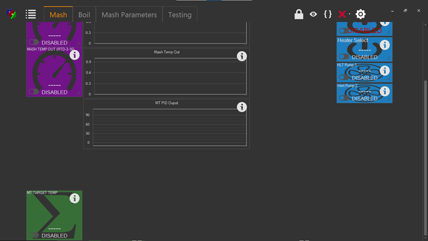
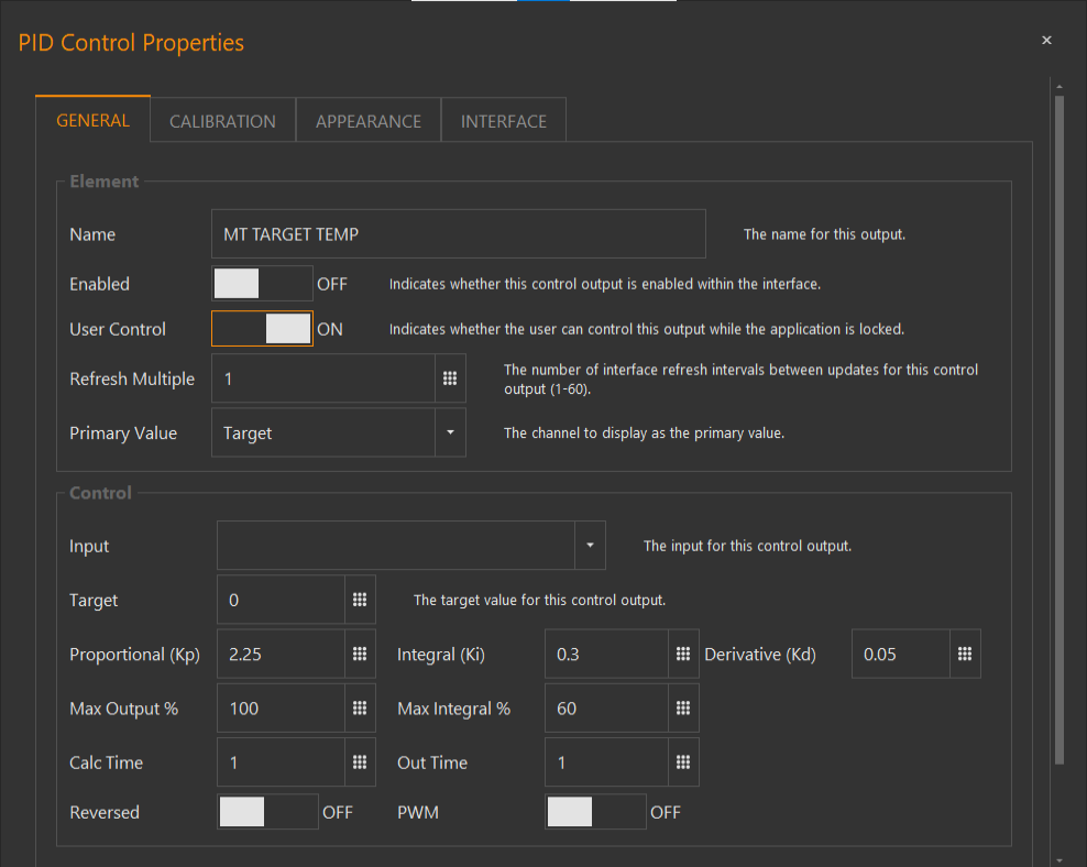
A before and after screen shot. The PID element changed position after I changed the "Input Control" to a different RTD in the "General" tab of the element properties. Only happens when I have the script window open and it is repeatable.

1594659756909.png


1594659784666.png
 
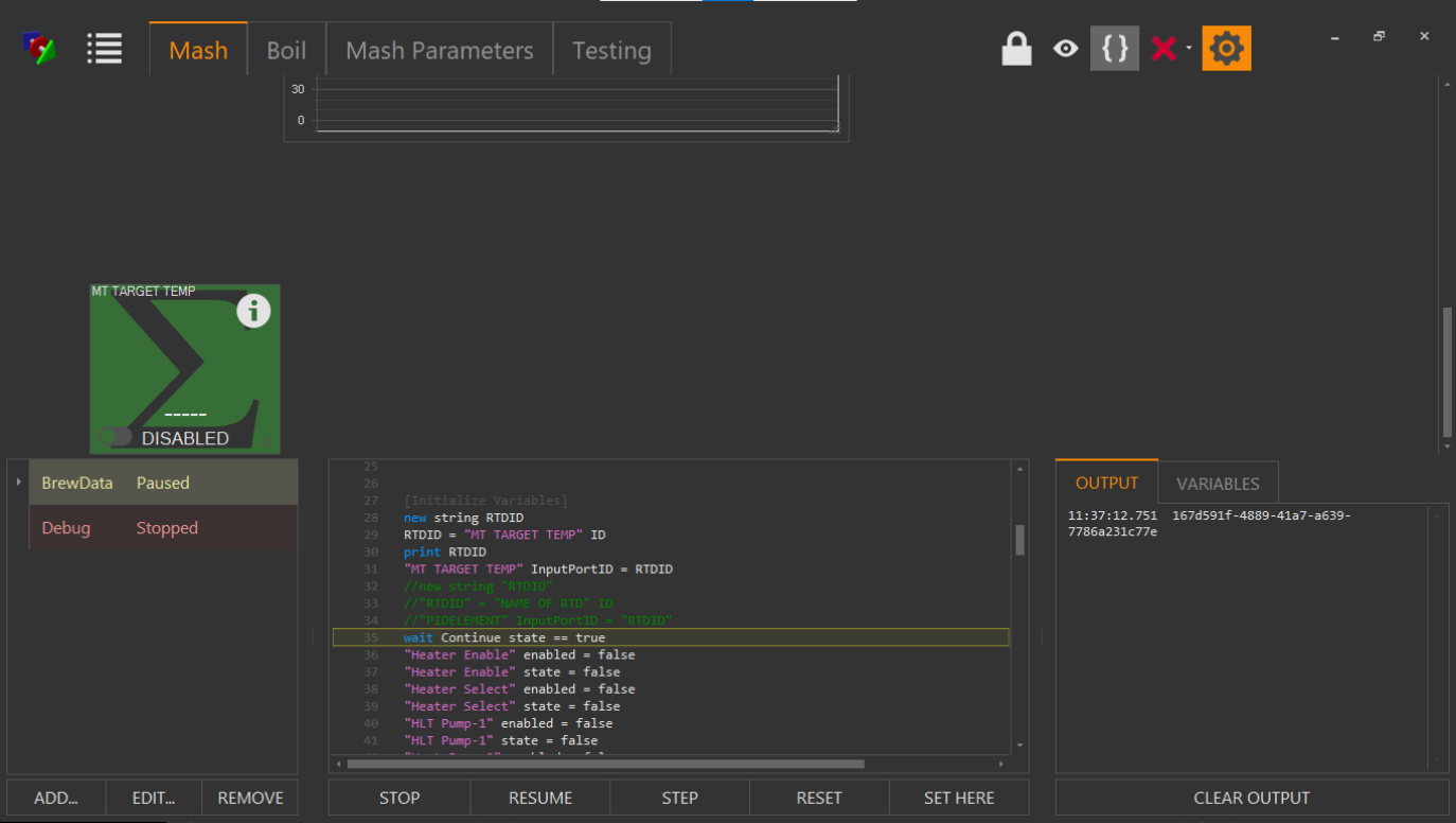
Something went wrong! I'm sure it was a scripting error on my part that caused BC (build 9) to crash but now I need help to correct a problem. I was trying to change the InputPortID using a script and now for some reason the input control is blank in the PID properties (unfortunately I deleted my original scripting error or I would have posted it). Now with the correct script I'm able to capture the new InputPortID (print RTDID) but it does not write the new portID to the PID using the script. It appears that the PID element has been deleted from the database (but still appears in the workspace) and stepping through the script past line 43 causes BC to crash. (I've stopped stepping through the script here since I don't want to crash BC again.) My intuition is to delete the PID and create a new one but I thought I would pass this on before doing anything that might cause a problem.


1594665533943.png


1594665572683.png


1594666043338.png
 
Yes, delete the PID Device Element and re-create it. BC should never crash with an exception and we want to squash those issues immediately. If you do manage to capture the crash, please do. It looks like in your script you are trying to assign the PID's input port with the ID of the PID device element, not the ID of a probe. That would never work. You would want the ID of the temp probe that feeds it.

If recreating the PID Device Element doesn't work, you will need to restore from a previous configuration.
 
A before and after screen shot. The PID element changed position after I changed the "Input Control" to a different RTD in the "General" tab of the element properties. Only happens when I have the script window open and it is repeatable.

View attachment 689280

View attachment 689281

Thank you for reporting this! I was able to recreate this and we will fix it. Bottom line is that when the script window overlaps elements, it causes scroll bars to become available, then when you scroll to see those covered elements, and they are "OK'd" (no change is even necessary), the absolute X,Y position is re-used rather than the relative position.
 
Back
Top