BruControl: Brewery control & automation software

Homebrew Talk - Beer, Wine, Mead, & Cider Brewing Discussion Forum

Help Support Homebrew Talk - Beer, Wine, Mead, & Cider Brewing Discussion Forum:

This site may earn a commission from merchant affiliate links, including eBay, Amazon, and others.
@swimIan I see at least 3 1 wire temp sensors in the pic. Do you by chance have more? Like 5? My serial started shutting down at 5 1wire.
 
When it comes time to update interface firmware, do you need to serially connect up to perform the update, or can you do it via network? I was thinking about putting some 8266 modules in some harder to reach places, but would think twice if I had to physically access them to do updates.
 
When it comes time to update interface firmware, do you need to serially connect up to perform the update, or can you do it via network? I was thinking about putting some 8266 modules in some harder to reach places, but would think twice if I had to physically access them to do updates.

Yes. Usb to PC with firmware. Until OTA happens (not sure about if that is even a thing for brucontrol).
 
Micro Motions I see on Ebay are $$$$$$$. Brass is not my favorite either but who wants to live forever? My water meter at the front of my property is brass. The connections on my hot water heater are brass. Bras or Plastic, pick you poison.
My concern with brass is beer brewing specific. Beer (wort) is slightly acidic, which is what causes the concern for me when using brass.

I have no concern at all using brass with culinary water.
 
littlewashintonbrewery,
You are correct that brass can contain lead, but many states, such as my state, Maryland, no longer allows lead to be in brass. Oakburn, if you wish to use brass, just make sure the brass does not contain lead. It will be stated on the product. If from overseas, I would think twice. Admittedly, I used U.S. made brass to brew for over 20 years, but I did update my brewing equipment, and did switch to SS for any acidic processes.
 
Hysteresis question/issue:

I'm trying to script an override timer to reset a hysteresis value if a timer runs past a certain time. When I issue a "Hysteresis Device" value = 0 to stop the device, it stops, then it comes back on during the next refresh cycle to the interface. I was hoping it would adhere to the On Delay time set, but it only appears to do that if the target temperature is met. It also does this if I issue a "Hysteresis Device" Enabled = 0 command then re-enable it. Is this a bug or intended operation?

Edit: After further testing, issuing "Hysteresis Device" value = 0 does not appear to do anything while the device is in use. While the screen says the device goes off then back on, the relay itself doesn't change state.
 
Last edited:
Well, I bought the flow meters. Look decent quality and the manufacturer said food safe, but they are Chinese. I only plan to use them to flow Mash and Strike water only from my Huge HLT. It does not have a sight tube one it and neither does my Mash Tun, I use a marked stick to measure volume before the Mash and just judge the Sparge based on look. I was going to add a Sight Gauge to the Huge HLT, but I am thinking volume sensor now. The issue is where to mount the sensor. If on the bottom, the water level could be as much as 28 inches above the sensor. Side mounted would be more like 24 inches if I mounted low. It is a 75 gal tank.

So water only and no Wort.

They are also G12 so I got some converters to NPT off amazon (also brass). Have mounted my new Enclosure and started to do a little additional wiring. I bought a 16 port dumb ethernet switch. I plan to have one Arduino Mega in my Cold Room where we ferment. One will be in the Main Brewery area. They may be connected via Serial or Ethernet. I am wiring for both.The one in the Cold room will be ethernet as that is hard to do any wiring even though I have done 100s of miles of pulling cables over the years. It is just a little difficult for that location.
 
fwiw, "Lead Free" doesn't actually mean "Zero Lead".
For example, this is a summary of the Maryland law effective as of 2012, which is basically a federal regulation adopted two years in advance.

"The Environmental Protection Agency (EPA) will require all plumbing products to meet NSF/ANSI Standard 61 Annex G (NSF 61-G) effective January 1 2014. NSF 61-G is a standard to limit the weighted average lead content of plumbing products to ≤ 0.25% for any plumbing that delivers potable (drinkable) water.

The state of Maryland’s Department of Labor, Licensing, and Regulation has decided to amend the current plumbing code to enforce NSF 61-G two years in advance.

Starting on January 1, 2012, all plumbing systems under the Maryland State Board of Plumbing’s code delivering potable water will be required to meet NSF 61-G."


So while one could debate whether "0.25% average by weight" lead content is deleterious to anyone's health it's still non-zero...

Cheers!
 
PID question: When does the I term start accumulating? Initial ramping or just before set point or only after reaching set point?
 
Hysteresis question/issue:

I'm trying to script an override timer to reset a hysteresis value if a timer runs past a certain time. When I issue a "Hysteresis Device" value = 0 to stop the device, it stops, then it comes back on during the next refresh cycle to the interface. I was hoping it would adhere to the On Delay time set, but it only appears to do that if the target temperature is met. It also does this if I issue a "Hysteresis Device" Enabled = 0 command then re-enable it. Is this a bug or intended operation?

Edit: After further testing, issuing "Hysteresis Device" value = 0 does not appear to do anything while the device is in use. While the screen says the device goes off then back on, the relay itself doesn't change state.

The Hysteresis value property is read only as it is determined by the interface. Yes you can temporarily override it via your script but it will only reflect in the device element, not in the actual device. Enabled property will enable or disable the device, which will turn it off completely. This is all intended operation.

What are you trying to do? When you say “reset a Hysteresis value” - what does that mean? IMO you should just change the ON setpoint and the offset.

If you are looking for some type of custom Hysteresis, you might be better off scripting your own using a standard digital output.
 
PID question: When does the I term start accumulating? Initial ramping or just before set point or only after reaching set point?

Functionally, it starts immediately, though always lags one calculation cycle. If you want to see it accumulate, you can turn on the debug to level two (via serial terminal) and it will report the error components.

In terms of concepts: Proportional looks at the difference between the target and the current measurement. Integral looks at the same difference but adds it up over time. These two combined are what we need to successfully heat our kettles (D doesn’t attribute much). For example, if you just had P (relatively low coefficient) the heat going in would not match the heat leaving, and you would get a steady state temp under your target. Add a little I and that error builds enough over time to allow the heat to increase to achieve the target.

Hope that helps!
 
The Hysteresis value property is read only as it is determined by the interface. Yes you can temporarily override it via your script but it will only reflect in the device element, not in the actual device. Enabled property will enable or disable the device, which will turn it off completely. This is all intended operation.

What are you trying to do? When you say “reset a Hysteresis value” - what does that mean? IMO you should just change the ON setpoint and the offset.

If you are looking for some type of custom Hysteresis, you might be better off scripting your own using a standard digital output.

Thanks for the confirmation. I'm scripting out a failure process when a fridge doesn't meet a setpoint in a desired amount of time. I wanted it to try to cycle (using the ondelay) 2-3 times running no more than an hour or so, and if it doesn't meet the setpoint shut the device down and raise an alarm. I can roll my own code with no issue, was just hoping to save some time and leverage an existing element. I also decided last night that I wanted a "make" time to trigger and a minimum run time, so I've already started down that path.

Thanks,
Joe

Edit: Also, good idea about changing the setpoint, that allowed me to do what I wanted. Didn't realize the "Hysterersis" Value was read only, hence my issue.
 
Last edited:
Yeah we probably should document that better. Technically you can write the value in the element, but as you noted, as soon as BC polls the interface, it will be updated again.

In the User Manual:
Hysteresis
o InputPortID (number)
o Target (number)
o OnOffset (number)
o OnDelay (number)
o Value (true/false)

Are these all just "read only"?
 
I was able to write to Target, OnOffset, and OnDelay. Didn't try InputPortID. Writing the Value makes the element visually change state, but on the next poll cycle will go back to whatever state the device is really in.
 
Is a variable with value of zero equivalent to false?

new bool x
x = True
if x == 1
print x
endif
No error thrown!

x is true. you must assign a boolean value (0,1, True, False) {x = Boolean Only}
You can evaluate x == only with a a boolean value (0,1, True, False)

It appears that 0 = False and 1 = True and you could use either in Scripts.

If you use a non boolean value in either statement, an error is thrown:

[ERROR: '2' is not a valid boolean value]
 
I was able to write to Target, OnOffset, and OnDelay. Didn't try InputPortID. Writing the Value makes the element visually change state, but on the next poll cycle will go back to whatever state the device is really in.
Thanks! I am trying to figure out the Scripting Code and what it will (or will not) do.
I am writing some simple Scripts to test most of what the User Manual says it will do.

I would be trying it as soon as I have mine wired. I have used a BCS in the Past and have changed the Target and the Swing (offset). I would think that InputPortID would have to be R/O. I think the Value would be of little use since it changes every cycle. Not sure how the PortID is important either.
 
Not sure how the PortID is important either.

If you can change it, I could see it being useful to change the interface ID without having to rebuild the device. Otherwise, I guess you could read all the values from your devices to create an "as built" wiring diagram?
 
One thing I do think is needed is to be able to somehow change the Device Interface of a Device Element. One potential issue I could see in the future if you have to replace an Arduino because it got fried. Since I am so new to this, I just might not understand enough. I was trying to figure out loading different configurations and while doing so, it looks like if you change out a physical Arduino for a different one, you have lost any Device Element and get a Fatal Error in BruControl, even if "named" the same. It looks like the Device Interface attribute of a Device Element is somehow tied to the physical device somehow.
 
One thing I do think is needed is to be able to somehow change the Device Interface of a Device Element. One potential issue I could see in the future if you have to replace an Arduino because it got fried. Since I am so new to this, I just might not understand enough. I was trying to figure out loading different configurations and while doing so, it looks like if you change out a physical Arduino for a different one, you have lost any Device Element and get a Fatal Error in BruControl, even if "named" the same. It looks like the Device Interface attribute of a Device Element is somehow tied to the physical device somehow.
This might be a difference between serial and Ethernet interfaces. AFAIK you can swap out an Ethernet device for another as long as the IP address doesn't change.
 
In the User Manual:
Hysteresis
o InputPortID (number)
o Target (number)
o OnOffset (number)
o OnDelay (number)
o Value (true/false)

Are these all just "read only"?

As a general rule, if it’s a field in the element you can enter data into, its read and write. If not, it’s read only. So for the above, the first 4 are R/W and the last is RO.
 
new bool x
x = True
if x == 1
print x
endif
No error thrown!

x is true. you must assign a boolean value (0,1, True, False) {x = Boolean Only}
You can evaluate x == only with a a boolean value (0,1, True, False)

It appears that 0 = False and 1 = True and you could use either in Scripts.

If you use a non boolean value in either statement, an error is thrown:

[ERROR: '2' is not a valid boolean value]

Yes, we gave the flexibility of true, false, on, off, 1, and 0 to be interchangeable.
 
Thanks! I am trying to figure out the Scripting Code and what it will (or will not) do.
I am writing some simple Scripts to test most of what the User Manual says it will do.

I would be trying it as soon as I have mine wired. I have used a BCS in the Past and have changed the Target and the Swing (offset). I would think that InputPortID would have to be R/O. I think the Value would be of little use since it changes every cycle. Not sure how the PortID is important either.

InputPortID gives you the ability to change the source of a Hysteresis or PID input. For example, you could have a Fermenter refrigerator drive off of a probe in the refrigerator, then switch it to a probe in the fermenter itself (I’m honestly not sure why you would, but you can!). If you can switch it manually, we give you the ability to switch it in your script, too.
 
One thing I do think is needed is to be able to somehow change the Device Interface of a Device Element. One potential issue I could see in the future if you have to replace an Arduino because it got fried. Since I am so new to this, I just might not understand enough. I was trying to figure out loading different configurations and while doing so, it looks like if you change out a physical Arduino for a different one, you have lost any Device Element and get a Fatal Error in BruControl, even if "named" the same. It looks like the Device Interface attribute of a Device Element is somehow tied to the physical device somehow.

You should have no problem swapping physical interfaces. Network can be different between Ethernet or WiFi as long as the IP and interface type are the same. Loading different configs should not cause any issues.

You cannot tell a particular device element to be on a different interface - we just don’t have the cross-check in place to make sure it’s compatible, but that is something we could do in the future.
 
OK. As I said, I do not know enough yet. What about swapping out a Serial Interface with a different Physical Device? I am reading through this thread from the beginning. On page 6 so far. Slow going.
 
Hey @BrunDog and others--I'm working on refining my brew day script after my first brew, specifically attempting to use my mash kettle volume sensor to detect a grainbed restriction/stuck mash situation and adjusting the proportional valve on the other side of the pump to compensate. BrunDog has this in his script in an "automash" loop that checks the mash volume and adjusts the valve if it is above or below a specified range relative to the original mash volume.

Unlike BrunDog's mash volume sensor, mine is mounted to the side of my mash tun, above the false bottom. Is there any way to use a pressure sensor located there to detect a sticking mash? I was talking it over with my friend, and he was of the opinion that if the mash starts sticking and the pump pulls a small vacuum under the false bottom, the pressure above the false bottom will remain more or less the same, thus rendering the pressure sensor, as currently located, fairly useless for detecting a stuck mash. Have any others used a pressure sensor (or flowmeter--I have one of those too) to detect mash problems and automatically adjust their recirculating pump flow in response?

Thanks!
So, unfortunately in my brew day yesterday, I had the opportunity to further investigate this question, as my mash was sticking horribly due to an overaggressive crush. I made some interesting (to me, anyway) observations. As predicted by my friend, @RiverCityBrewer, and @BrunDog, once the mash stuck, the pressure/volume reading read the full volume of the mash. However, prior to the mash sticking, and I surmise as the mash bed was compacting, the volume measurement did drop. And relatively predictably, if the volume measurement got too low, the next thing that happened was that the flow would drop and I'd end up over the mash tun stirring the grains off the false bottom before restarting recirculation. Based on my observations, I think the automash logic might actually work for me to prevent a stuck mash by slowing the flow as it detects the bed beginning to compact!

The constantly sticking mash made for a long brew day, but, hey, I might have made some observations that will help reduce them in the future!
 
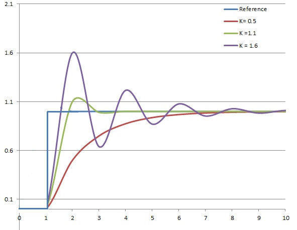
Man!! This guy is good! Yes @smort, you are correct. We clamped the integral from zero to max, not negative max to positive max. This means that the integral error will stop at zero if the input is “past” the target. We did this knowing our applications are unidirectionally biases (meaning our kettles heat up actively by the element but have no mechanism to actively cool).

But in truth, a real control system (like a flexible arm on a gear drive positioning a mass into a a specific location) would need the integrator to work in both directions. This makes for a more aggressive system and tuning potentially trickier.

That said, do you want the integrator to work negatively? It will probably make overshoots undershoot more, but if the consensus is desired, it’s a simple switch in the FW. I suppose we could make it a setting in the element properties but that would probably add a lot of user confusion.

Anyway... nothing to see here. Carry on!


I ran my still for 13 hours today turning unhopped beer into malt whiskey, 11 hours of that it I was trying to get the PID tuning right on my reflux condenser cooling valve, the BC PID seems to not like cooling for the reasons mentioned, I would really appreciate the ability for the integrator to work the other direction, I think it is causing my issues, and the lag might be a factor also.....

And a funny thing, if I ran with Ki and Kd set to zero and tinkered with just Kp, i could get it to do pretty small oscillations, but they were not centered over the set point, they oscillating above and below an imaginary line about 5 degrees below the setpoint... I understand that integral takes care of steady state error, but this seemed like the algorithm was scared to get close to the setpoint, every time it got close, it did an about face and went the other direction... wierd... I could have taken a hundred screenshots with different unexplained situations..

Side question: I started to put in very small Ki, it seemed to not do anything and then all of a sudden it would add far too much... my question is.. if i put in 0.005, it shows as 0.01 when i click away, and if i put in .004, it shows 0... I guess that the question is: "Is .01 the smallest non-zero value we can use?" is it reading the .005 or is it rounding it up to 0.01?
 
Last edited:
doing some tests today with a script running trough some PID values of Kp 0.1 to .30:
(orange line shows how 'closed' the valve is.. the top clipped area is 75% PWM, which translates to 7.5v, which is just before where the valve actually starts flowing. when the orange line goes down, it is allowing more cooling water. the setpoint is 160, which it never reaches(well at least with my range of P values so far...)
BruControl Cooling PID Kp .1-.25.png


This is not moving it fast enough, so stopped it at .25 and I re wrote the script from .10 to 5.0


I have had a funny error show up:
BruControl Cooling PID error.png


No issues in the normal script log. I am more aware of what fixes it now, at first I was flustered. I first reset the arduino, then the script, then reset BC fully before realizing that just disabling/re-enabling the PID fixed it. I will load v.44J on the mega later today.. not sure what version of 44 is on it now
 
Last edited:
OK, ran the script stepping Kp from .10 to 3.0.. Interested in what Kp others would use, I am thinking 0.9 and doing a similar trial with Kd, then finally Ki....

BruControl Cooling PID Kp .1-3.0.png


general question: I never overshot the setpoint of 160... with my Sestos, even with a tiny Ki, I could way overshoot by adding too much Kp..
 
I ran my still for 13 hours today turning unhopped beer into malt whiskey, 11 hours of that it I was trying to get the PID tuning right on my reflux condenser cooling valve, the BC PID seems to not like cooling for the reasons mentioned, I would really appreciate the ability for the integrator to work the other direction, I think it is causing my issues, and the lag might be a factor also.....

And a funny thing, if I ran with Ki and Kd set to zero and tinkered with just Kp, i could get it to do pretty small oscillations, but they were not centered over the set point, they oscillating above and below an imaginary line about 5 degrees below the setpoint... I understand that integral takes care of steady state error, but this seemed like the algorithm was scared to get close to the setpoint, every time it got close, it did an about face and went the other direction... wierd... I could have taken a hundred screenshots with different unexplained situations..

Side question: I started to put in very small Ki, it seemed to not do anything and then all of a sudden it would add far too much... my question is.. if i put in 0.005, it shows as 0.01 when i click away, and if i put in .004, it shows 0... I guess that the question is: "Is .01 the smallest non-zero value we can use?" is it reading the .005 or is it rounding it up to 0.01?

We’ve changed the integrator direction a couple of times. I can’t remember how it’s currently set in 44J but it will not really matter unless the temp is above the target for a while.

Your “funny thing” is not funny at all - this is normal operation. As you increase Kp the imaginary line will move up and so will the oscillations. Think about it - you have a unidirectional system - you are heating only, not heating and cooling. And that input (heat) is escaping. So as the temp climbs, at some point the proportional error gets small enough that the heat escaping exceeds the heat being added. You cannot have a scenario where zero power input will hold your desired temp (insulate the vessel well and this gets better). This is why the integrator is needed to hit your target. See the dynamic graphic under “tuning” here and you will see Kp alone will not achieve the setpoint: https://en.m.wikipedia.org/wiki/PID_controller#Ziegler–Nichols_method

I’m not sure the minimal input offhand but these numbers are really small anyway. I’m not sure how going from 0.005 to 0.01 is adding way too much. Keep in mind we have limited resolution so there does need to be some steps.
 
doing some tests today with a script running trough some PID values of Kp 0.1 to .30:
(orange line shows how 'closed' the valve is.. the top clipped area is 75% PWM, which translates to 7.5v, which is just before where the valve actually starts flowing. when the orange line goes down, it is allowing more cooling water. the setpoint is 160, which it never reaches(well at least with my range of P values so far...)
View attachment 615685

This is not moving it fast enough, so stopped it at .25 and I re wrote the script from .10 to 5.0


I have had a funny error show up:
View attachment 615686

No issues in the normal script log. I am more aware of what fixes it now, at first I was flustered. I first reset the arduino, then the script, then reset BC fully before realizing that just disabling/re-enabling the PID fixed it. I will load v.44J on the mega later today.. not sure what version of 44 is on it now

It’s tough for me to debug this without familiarity of the hardware. Just thinking about your comment above “just before where it actually starts flowing”... bottom line is if you don’t have a good linear range of your controlled device (driven by the output), it will be very difficult for the PID to control the system. The Kp alone relies on a proportional output to follow the input - if the valve is not linear and wide-ranged, non-custom software cannot fix it.
 
I understand approaching if Kp is too small, but it *should* overshoot with a large Kp, correct? The thing is, my temp *never* gets above target, that is shown in the graphs. set point is 160, it never, not one time reached 160, not overshot, not ever...

again, I understand what the integral function is, it integrates, or adds up the error over time and uses that in the control loop to reach the target... I completely understand how Integral works... I really do... Look at the graph in post 1957 again, the swings *decrease* as Kp goes up and it slowly approaches the setpoint... every PID I have ever worked with could overshoot with just Kp..


Here is the wiki page, showing the result of increasing Kp(they call it K), while holding the D and I constant.. I am unable to get anything but the red line


PID_varyingP.jpg
 
Back
Top