BruControl: Brewery control & automation software

Homebrew Talk - Beer, Wine, Mead, & Cider Brewing Discussion Forum

Help Support Homebrew Talk - Beer, Wine, Mead, & Cider Brewing Discussion Forum:

This site may earn a commission from merchant affiliate links, including eBay, Amazon, and others.
OK, here is Kp at the chosen 0.9 value and stepping up Kd, I chose 1.0, but after waiting about 5 minutes, it looked more like what 0.2 gave... I had tried setting the max to 80% because the valve, even though it has a keyhole profile insert, still flowed a trickle at 75... that was a bad idea, you can see that leaving the trickle in made it much more stable...(look at the smoothness of the graph when the orange line is clipped at 75). I may have to start all over with the Kp trials and using 80% max...


BruControl Cooling PID Kd .01-4.0.png


Alos, the analog output going haywire seems to be tied with me switching contactors on and off, they are 24vac, so should not need a diode, but will look at suppressors, I have a couple, will get a couple more and make sure I have one on each.....
 
Last edited:
No, not necessarily. Heated systems very often will not overshoot (though not sure this is what you are doing). Overshooting will occur when their is a lag between the output and the input - that is the point of PID. If your sensor was immediately measuring the temperature of the heated liquid, there would never be a lag because there is no storage or windup of energy (not like a spring for example). Therefore no overshoot because as the temp is achieved, the error approaches zero, and zero times any output will be zero output.

I guess I am trying to understand what the issue is. We should not want overshooting or oscillation. Are you able to achieve the output you want?

Regarding your comment... "every PID I have ever worked with could overshoot with just Kp", I would need to challenge this. If you have performed a drop-in replacement with BC versus the previous PID, then the result should be the same as there is no funny math here.

Perhaps you can explain (or send pics) of your control system? It doesn't sound like we are controlling heat, but cooling, but via a non-linear valve? Please explain in more detail so I can help debug what you are trying to achieve.
 
OK, here is Kp at the chosen 0.9 value and stepping up Kd, I chose 1.0, but after waiting about 5 minutes, it looked more like what 0.2 gave... I had tried setting the max to 80% because the velve, even though it has a keyhole profile insert, still flowed a trickle at 75... that was a bad idea, you can see that leaving the trickle in made it much more stable...(look at the smoothness of the graph when the orange line is clipped at 75). I may have to start all over with the Kp trials and using 80% max...


View attachment 615730


Alos, the analog output going haywire seems to be tied with me switching contactors on and off, they are 24vac, so should not need a diode, but will look at suppressors, I have a couple, will get a couple more and make sure I have one on each.....

With all due respect... I have no idea what is represented here. I don't know what RC is etc. Please explain the hardware, etc. so I can help.
 
OK, that is fair... maybe look at the .gif at https://en.wikipedia.org/wiki/PID_controller#Ziegler–Nichols_method

When the animated image first starts, Ki and Kd are zero and as they raise Kp you see they get overshoot... this is not the behavior I observed as shown in post 1957... I also expect more dampening as as I increase Kd, but I see small jumps, then huge jumps as much as 25% of scale in a single cycle, which the D should eliminate if Kd is reasonably big, (then again, maybe I am not setting D high enough. Can we get the actual ranges of useful or valid numbers added to the manual, obviously 0 is a minimum, so the smallest non-zero number that is recognized and acted on)... I think the next step is that I will have to hook up a computer via serial to enable the debugging to see the actual calculations
 
Functionally, it starts immediately, though always lags one calculation cycle. If you want to see it accumulate, you can turn on the debug to level two (via serial terminal) and it will report the error components.

is this the “%1&14;”? I am guessing we run InterfaceSetup.bat , select 2 for network setup, select the com port, and click enter to start Termite and then enter the %1&14; I will try to run my setup again on Thursday and take some PID debugging notes to share along side of the graphs. Since it is a bit of an ordeal to get my setup running. I like to plan ahead and have a few test scripts ready with much larger Kp and Kd and then Ki.

Since termite does not give us the ability to filter things like wireshark does, a quick search shows that wireshark can monitor USB serial interfaces via usbmon or USBPcap, so that may be the ticket... but may take some research, but it sure would be nice to weed out the temp sensor messages that I imagine will flood in...
 
OK, that is fair... maybe look at the .gif at https://en.wikipedia.org/wiki/PID_controller#Ziegler–Nichols_method

When the animated image first starts, Ki and Kd are zero and as they raise Kp you see they get overshoot... this is not the behavior I observed as shown in post 1957... I also expect more dampening as as I increase Kd, but I see small jumps, then huge jumps as much as 25% of scale in a single cycle, which the D should eliminate if Kd is reasonably big, (then again, maybe I am not setting D high enough. Can we get the actual ranges of useful or valid numbers added to the manual, obviously 0 is a minimum, so the smallest non-zero number that is recognized and acted on)... I think the next step is that I will have to hook up a computer via serial to enable the debugging to see the actual calculations

Again, heated systems like in brewing (I don’t know much about the distillation process) may not overshoot. The GIF we both quoted is a general control systems which have repeatable input/output differentiations based upon time. In a basic heated system, when the heat turns off, if the liquid is circulated/mixed well enough, the temperature WILL NOT increase - hence no overshoot. You seem to want it to overshoot but trust less is better.

Once again, it’s tough for me to know how your system performs without understanding the hardware.

I think the dialog says the input range but if not we’ll document it.
 
is this the “%1&14;”? I am guessing we run InterfaceSetup.bat , select 2 for network setup, select the com port, and click enter to start Termite and then enter the %1&14; I will try to run my setup again on Thursday and take some PID debugging notes to share along side of the graphs. Since it is a bit of an ordeal to get my setup running. I like to plan ahead and have a few test scripts ready with much larger Kp and Kd and then Ki.

Since termite does not give us the ability to filter things like wireshark does, a quick search shows that wireshark can monitor USB serial interfaces via usbmon or USBPcap, so that may be the ticket... but may take some research, but it sure would be nice to weed out the temp sensor messages that I imagine will flood in...

Yes, correct on the setup.

Regarding the “flood”, you are right. You will get both sensor and PID data. You want to disable anything else so you don’t get overwhelmed.

You know... quick thought. Perhaps PID is not the algorithm you should be using. Perhaps a simple Hysteresis or “approach logic” script which simply increases or decreases the output over time if the temp is outside of a defined window.
 
My hardware is a flow controlled cooling device. Think of it as a wort chiller and you have very cold water and are metering the flow to get a proper wort output temp... the PID as implemented is cooling the wort below the target, and as soon as the valve starts to close and gets near the target, the PID freaks out and opens flow really, really quickly, as in closed to full open in a second or two, and cools the whole chiller down and the hot wort takes a while to heat it back up... the PID reacts, but by this time, it is too late, and an oscillation happens far, far below the setpoint..


a little overshoot is completely normal. A lot of it, no, but a little is ok..... I am not saying I desire it, I am saying that it is something that is in every PID system when you increase P... I think it shows there is something else going on, a clamping to zero or something like that...

I guess what frustrates me is that with just Kp, (Ki and Kd at 0), the output signal that is rising, suddenly stops 10-15 degrees before the setpoint and starts decreasing... wouldn't a strictly P system not start unless it overshot? i can understand it if it stopped increasing.


My Sestos PID's do a spectacular job of hovering within 0.1 degrees of the target, and it can do that with a pretty wide range of acceptable range of constants... But they also have a 'heating' or 'cooling' setting... which may configure other back-end stuff like 'clamping' differently... I am awaiting some PG16 connectors for my valve cabling and I will wire up the valve to the box in a manner that I can quickly disconnect the valve form the mega and connect to the Sestos Box to control it, and then also connect the sestos PID box to the mega so that the BC interface can monitor the Sestos PID 0-10v output and graph it...
 
It seems we are stuck on the overshoot hamster wheel... I’m going to jump off. That said, if you are getting the result you want with dedicated PIDs and are not getting the same or better with BC, then we are obligated to get you right. Please email us and I’ll try to help offline rather than this thread (we’ll report back!)
 
PID Tuning takes a lot of home made whisky. Unfortunately, by the time you start to figure it out, too much whisky! Manual PID tunning is difficult. There are people who have a whole life time career doing PID Tuning and some companies exist that do nothing but. But I have a simpler question.

There are 3 items you can set with an SPI Sensor. (RTD)

Refresh Multiple Default = 1
Average Weight Default = 25
Poll Rate Default = 500

Are the defaults good for most RTD sensors?

Why would you want to change them from the defaults?

I read about Current Reading at Average Weight 100% in the User Manual so I know about that.

I would assume if there was a calibration issue, you would use the calibration dialog and not these.
 
Refresh multiple is the "per number" of cycles that the sensor is polled during interface refreshes. So, if the interface refresh interval is 2 (seconds) and the refresh multiple is 2, then 2x2 = 4, so the sensor will be polled every 4 seconds (aka every other interface refresh). We default both to 1 second but if you don't need that level of update rate, it can reduce network traffic (not that its much to start with). You can leave this as default without concern.

Average Weight is how much a new reading gets averaged into the existing reading. Lower number reduces aberrant jumping around but also makes the response to rapid changes slower. 25% (default) means each new reading * 0.25 is added to the existing value * 0.75. This default is good for RTD but you could also make it a bit lower, say 20 or 15%, for slow changing systems. I would refrain from setting this at 100% per the manual.

Poll Rate is the frequency internal to the interface that the sensor is read. This is different than the Refresh, where the value goes from the interface to BruControl. 500ms means it is read 2x per second (and each new value is averaged in per above). Theoretically, as you decrease his (poll faster), you would decrease the average weight too. But again, this default is good.

Yes, calibrate via that dialog. And have fun and drink more whiskey!
 
Ok A Script Question'

In your sample

new string Status

...

Status = "Ready to Start"


What is "Status" variable doing. I did a search and all you do is

Status = "Some String"

Does this have to do with the Variable Element?
 
Ok A Script Question'

In your sample

new string Status

...

Status = "Ready to Start"


What is "Status" variable doing. I did a search and all you do is

Status = "Some String"

Does this have to do with the Variable Element?


It is just a string, and likely used to display the current status to the screen or to a display. I use this as a similar item to naming a state in the controller we used to use.

I use:
Code:
new string CurrentState
...
CurrentState = "Heating Up"

to get it to display, you would create a variable in the workspace:
Name: Current State
Script: <put the script that defines this variable here>
Variable: CurrentState <<-- notice no space, but above does have one for readability on the screen... this one must match the one in the script exactly.
 
new string CurrentState
CurrentState = "Heating Up"
print CurrentState
stop "CurrentState_Script"


How do I get it to display is what I do not understand:

attached is a copy of my variable
variable display.png
 
new string CurrentState
CurrentState = "Heating Up"
print CurrentState
stop "CurrentState_Script"

View attachment 615899

Remove the print CurrentState and stop "CurrentState_Script" lines. You'll also need some loop logic in there or the script will throw an exception. If the script is not running the variable will just display "--------".

Try creating a counter increments by one every second.

[setup]
new string CurrentState
new value Counter
CurrentState = "OFF"
Counter = 0

[loop]
sleep 1000
Counter += 1

if Counter == 5
goto State1
endif

if Counter == 30
goto State2
endif

else
goto loop

[State1]
CurrentState = "Heating Up"
goto loop

[State2]
CurrentState = "Shutting Down"
goto loop

Had to change slightly:

[setup]
new string CurrentState
new value Counter
CurrentState = "OFF"
Counter = 0
[loop]
sleep 1000
Counter += 1
if Counter == 5
goto State1
else
goto loop
endif
if Counter == 30
goto State2
else
goto loop
endif
// else statement moved to between if and endif
[State1]
CurrentState = "Heating Up"
goto loop
[State2]
CurrentState = "Shutting Down"
goto loop


How did the Variable Element Know what to display?

It worked fine. What I was missing were three important pieces of information.
1. Script Variable Name placed in Variable Name Box on the Variable Properties Dialog: Not that apparent until it was.
2. Script Name where 1 above is declared and manipulated in Script Field. Easy to figure
3. Script MUST be running. I had no idea.

Part of the issue is the name of the Element. It is named Variable. I thought that this was like a script Variable that you were somehow declaring when you created it. I was trying to figure out how to set the type and how to use in a script. It is NOT a Variable but an Element that displays the value of a normal script Variable in a named enumerated Script WHILE that script is running.

Unfortunately, the User Manual is a little thin on the Variable Element.

I was creating a Wish List and something like this was #1 on my list. I can now use this instead. It answers a lot of the other questions I had about having the same Element on different Workspaces.

As an example, I can use this to display the Value of a Button or I can use it to tell me if a Pump is On or Off, regardless of which Workspace the Pump Digital Out is on.

It gives no control but you could use a button for that if needed.

It is a Display of Variable Value Element where the Display is set by a variable in a Running Script.

Varianle Propertires new.png
 
I agree the documentation could stand for some improvement. Things will get both clearer and more confusing with v1.1...

“Variables” will be those variables used in scripts only. They are local to the script and only in place while it is running.

“Inspectors” will be the new name of variable elements. These “inspect” the value of a script variable.

“Globals” are unique elements which contain values (or dates, text, etc.). They are permanent (they are stored in the configuration file) and are accessible across scripts.

Now, on the topic of the release candidate (beta), we were prepared to release it but a tester reported an element font size change upon start-up, so we are investigating that. Once we get clarity, we’ll post it up.
 
looking forward to v1.1. I am writing my first production script to fill vessels. On the BCS I had a Process and will have a Workspace on Brucontrol.


Since I understand the Variable Element, I was able to display a graphic of my white pump on or off. (Using Visibility Property and 2 Variable Elements with different background images stacked on top of each other)

I have 2 immediate questions.

1. Why Enable or Not. I understand "how" and what "SomeDeviceElement" Enable = True does, I just do not understand why you would not most of your Devices enabled on Startup.

I was writing a script to do so, but before I continue, I need to understand why you would NOT want Device Elements Enabled.

Memory issues?
Stack issues?
Overhead?

Basically by making the Value False, the On Screen Element cannot be manipulated On or Off. I can understand that reason. Are there other "whys". Generally I would have a Pump Workspace where I could Manually control a Pump with its Device Digital Out Element. I would want them enabled. On other workspaces I would have Variable Elements to display the State of the Pump and a Button to control if needed.

my start of the enable with an autostart Script "Enabler"

// Enable lots of Widgets
[Pump]
"Red Pump" Enabled = True
"White Pump" Enabled = True
"Blue Pump" Enabled = True
"Green Pump" Enabled = True
"Yellow Pump" Enabled = True
stop Enabler

That Brings up the second question.

Is a [Section] specific to a script. In other words, can I have a section named [Pump] in Script 1 and again in Script 2?
 
There is no reasons why you can't have all devices enabled at all times, including at startup.
I have all but 3 of mine enabled at all times. The 3 that are not are my heating elements. They are disabled by default, so I can't accidentally turn the element on (dry fire). There is zero reason for me to use these elements outside of a script, ( I do nothing manually) so it was an easy way to do it for me.

Sections within scripts are specific to the script. You can't name 2 sections the same in script, but you can have the same sections across scripts.
 
Device Elements are “running” when they are enabled. Maybe that’s ok, maybe not. For example, a PID Control Element is probably not something you want enabled unless you are actively using it during that part of your process. Digital Output Elements are typically on or off, so maybe you don’t care if they are enabled but passively off. For those, I guess the risk of turning them on unexpectedly is higher (user accidentally changing state), but that’s your call.

Device Elements which read data such as temperature sensors or analog inputs do require more overhead, and while that shouldn’t matter, I do think it’s good general practice to reduce overhead whenever possible and free up CPU, storage, etc. resources.

I have seen some users combine enabled devices with visibility via their scripts, so when a device is disabled, it’s not cluttering if the workspace as an”dead” element. Again, your call. We try to take away rules and rigidity and let you build it as you want it. Like Burger King.

Oh, I do suggest that in script sections where you enable digital out devices like your colored pump example above, that you set the state first. You wouldn’t necessarily want them to restore their last ON state unexpectedly during a startup. I personally set all my device element states and statuses via a singular script (called “Brewery Reset”. I call this script manually and at the end of certain other scripts. Sometimes automation can so what it is supposed to do but not what you are expecting following unknown states (like a restart).

Yes, sections, like variables, are local to the script they reside in, so duplication is ok. Keep in mind that Elements are universal, so these names cannot be duplicated.
 
Last edited:
Exactly what I needed to know. My thoughts exactly. I would only enable my heating elements just before using them in a script. I guess I can stick all the heating elements on a separate workspace and just call when needed in a script. I would use the Variable Element trick to see the State.
 
I agree the documentation could stand for some improvement. Things will get both clearer and more confusing with v1.1...

“Variables” will be those variables used in scripts only. They are local to the script and only in place while it is running.

“Inspectors” will be the new name of variable elements. These “inspect” the value of a script variable.

“Globals” are unique elements which contain values (or dates, text, etc.). They are permanent (they are stored in the configuration file) and are accessible across scripts.

Now, on the topic of the release candidate (beta), we were prepared to release it but a tester reported an element font size change upon start-up, so we are investigating that. Once we get clarity, we’ll post it up.


The layout looks like this:

yhhn1Jo.png


As Brun says they change a bit.. A global looks like this:

EdNIZsz.png


I use this for instance, on my main brewery status screen, that way I can get a heads up display at what scripts are running, or any out put of variables, across all scripts and workspaces. In code you reference this almost as a device element. Where as you declare the "value" you want there.

f7K51lc.png


The inspectors are more the traditional only can inspect 1 script/variable.
(also you can see the output of "Input Recipe Parameters" in the status bar, from above)
da491KB.png
 
I did discover that Enable on a PID, PWM, Hysteresis and Duty Cycle Enable is the On Off switch for them already. For those, you would only want to enable = true to turn on.

Now that I can see the State of a Device Element (with the Variable Element) and control with a Button on more than a single workspace, I will likely build Workspace that are specific to part of a Brew Day rather than using only one. Just divide and conquer.
 
some errata:

Page 65 User Manual Improvement

Section

Sections Code is grouped into named sections. A section heading is declared using square braces. Sections are "script" specific and must be unique only within the same script. The same Section name can be reused in other scripts.

A ‘goto’ command is used to jump execution to a specific section.
[Loop]
Example: goto Loop

If a section name has a space in it, the ‘goto’ call to that section must be named with quotes.
[My Loop]
Example: goto "My Loop"

Error Warning:
No Section may be placed within an if-endif statement. Error thrown: [ERROR: 'end' statement without preceding conditional]

Not Allowed:
[Startup]
if x = y
[workspace1]
// Section Not Allowed Here!
.. do something
endif

No Section may be placed within an if-else- endif statement. Error thrown: [ERROR: 'else' statement without preceding 'if']

Not Allowed:
[Startup]
if x = y
[workspace1]
// Section Not Allowed Here!
.. do something
else
[workspace2]
// or Section Not Allowed Here!
.. do something
endif
 
I noticed an issue last night while setting up my glycol system on a ESP8266 NodeMCU using FW 43. I setup a hysteresis with a target of 40 and On Offset of 5 looking at a one wire temp sensor in the bath. I calibrated the probe and put a 1.7 degree linear offset on the probe. The hysteresis logic seems to look at the uncalibrated reading when evaluating its On or Off call. Can anyone confirm this?
 
Button Not working
I have the following code

// Water Workspace
[Enabled]
"Firehose_FM" Enabled = True //Port 2 Counter
"Big Mac_FM" Enabled = True // Port 3 Counter
"Firehose Valve" Enabled = True // Port 26 Out
"Big Mac Valve" Enabled = True // Port 30 Out
"Brewery Float" Enabled = True // Port 39 In
"Big Mac Float" Enabled = True // Port 46 In
"Fermentor Float" Enabled = True // Port 49 In
[White Pump Control]
new bool VbX1
VbX1 = "White Pump BTN" State // Control of White Pump on Pump Workspace
print VbX1
if VbX1 == True
"White Pump" State = True
else
"White Pump" State = False
endif
goto "White Pump Control"

If I just test with a switch, it works fine. It looks like the Button is not changing states when clicked.
 
You need to reset the button state in the script. The button is false until it is pressed, then it is true until you reset it's state back to false again.

Play with this code and you'll see what I mean

[setup]
"Button" State = False

[loop]
sleep 1000
wait "Button" state == true
if "Button" state == true
print "Button Pressed"
else
print "Button Not Pressed"
endif
goto loop


If you move the Button State = False to inside the loop, you'll be able to advance the loop only on the button press. If you leave it as is, it will wait until you hit the button the first time then stay true forever.

Hope that helps,

Joe
 
Modified
"White Pump BTN" state = False
[White Pump Control]
sleep 1000
wait "White Pump BTN" state == true
if "White Pump BTN" state == true
"White Pump" State = True
else
"White Pump" State = False
endif
goto "White Pump Control"


The Button turns the Pump On but not off.

I think I will stick to switches because I can see that the switch is on or off. Not having any visual indication of the button state makes it hard to troubleshoot. The switch is on/off. I do not know what type of control a button has, but it is not the same action as a switch. It may be just on off, but it does not seem to toggle in the code when you are trying to read it. The code first post above works fine just switching the control to a switch element vs a button.


It seems buttons are one change until reset somehow.
 
I believe your observation about button vs switch is correct. Pg 72 has a blurb about it at the bottom of the page.

I think for your use case here, a switch is a better choice. I am using a button as a way to advance my script after I've performed an action like adding grain, hops, etc.
 
I noticed an issue last night while setting up my glycol system on a ESP8266 NodeMCU using FW 43. I setup a hysteresis with a target of 40 and On Offset of 5 looking at a one wire temp sensor in the bath. I calibrated the probe and put a 1.7 degree linear offset on the probe. The hysteresis logic seems to look at the uncalibrated reading when evaluating its On or Off call. Can anyone confirm this?

This is correct. You cannot calibrate a 1-wire because the temp is determined by the probe, not calculated by the software (like thermistors or RTD).

I could see where you would want to display a different temp then is coming in, but still PIDs, etc will not follow suit.
 
Modified
"White Pump BTN" state = False
[White Pump Control]
sleep 1000
wait "White Pump BTN" state == true
if "White Pump BTN" state == true
"White Pump" State = True
else
"White Pump" State = False
endif
goto "White Pump Control"


The Button turns the Pump On but not off.

I think I will stick to switches because I can see that the switch is on or off. Not having any visual indication of the button state makes it hard to troubleshoot. The switch is on/off. I do not know what type of control a button has, but it is not the same action as a switch. It may be just on off, but it does not seem to toggle in the code when you are trying to read it. The code first post above works fine just switching the control to a switch element vs a button.


It seems buttons are one change until reset somehow.

This code will not work in both directions because you have an if evaluating the same as the wait preceding it. You need “toggling” to take place (wait for on, then wait for off).
 
Ok I think it is a one way button.

Internal Logic of the Button

If "Button" == False
Left Click = Button to True
end if

There is no method to click the button to False.

It is "on" until you reset it via script. It is totally different than a switch which can be toggled True to False

You CANNOT Toggle it Manually Off but ONLY reset to False via Coding.

The only manual thing you can do is Click "On" if it is Off.
 
This is correct. You cannot calibrate a 1-wire because the temp is determined by the probe, not calculated by the software (like thermistors or RTD).

I could see where you would want to display a different temp then is coming in, but still PIDs, etc will not follow suit.

Thanks for the clarification, I figured that the linear offset was handled at the HMI level but not pushed down to the processor. Having never used a one-wire before, I just wanted to spot check to make sure I wasn't crazy.

Thanks,
Joe
 
Ok I think it is a one way button.

Internal Logic of the Button

If "Button" == False
Left Click = Button to True
end if

There is no method to click the button to False.

It is "on" until you reset it via script. It is totally different than a switch which can be toggled True to False

You CANNOT Toggle it Manually Off but ONLY reset to False via Coding.

The only manual thing you can do is Click "On" if it is Off.

The button state is latched (like a ballpoint pen), not momentary (like a doorbell). Therefore, don't rely on the button to do the work - rely on the script. For example:

Code:
[loop]
"Button" State = false
wait "Button" state == true
if "Digital Out" state == ON
"Digital Out" state = off
else
"Digital Out" state = on
endif
sleep 100
goto loop

Here the script waits on a button press, inverts the output's state, and starts all over again. The sleep isn't technically required but could de-bounce button presses.
 
Last edited:
I got it: Orwellian: War = Peace False= True


// Water Workspace
"White Pump BTN" State = false
[White Pump ControlOn]
sleep 100
wait "White Pump BTN" state == true // Wait till Button Clicked
if "White Pump BTN" state == true
"White Pump" State = True // Turn on the White Pump
"White Pump BTN" State = false // Reset Button to false
goto "White Pump ControlOff"
endif
[White Pump ControlOff]
sleep 100
wait "White Pump BTN" state == true // Wait till Button Clicked
if "White Pump BTN" state == true
"White Pump" State = False // Turn oof the White Pump
"White Pump BTN" State = false // Reset Button to false
goto "White Pump ControlOn"
endif


It now acts like a toggle. Click the Button, The pump turns on. Click the Button again, the Pump Turns Off.
 
I believe your observation about button vs switch is correct. Pg 72 has a blurb about it at the bottom of the page.

I think for your use case here, a switch is a better choice. I am using a button as a way to advance my script after I've performed an action like adding grain, hops, etc.

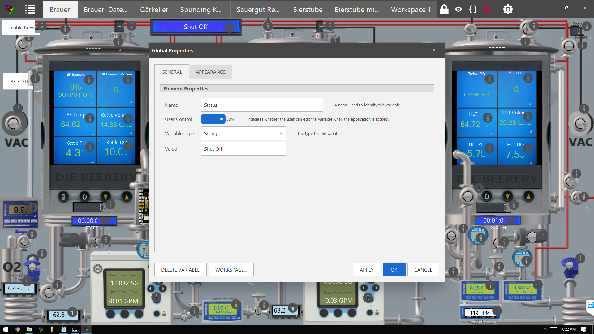
what is should read:

Buttons

buttons.png


Buttons have a State property which can be read or written.

Read:

New bool x

x = “Button 1” State

Set:

“Button 1” State = False

A Button may also be Left Clicked or Touch Screened to turn from Off (False) to On (True)

{One Way: False to True Only!}

The State of the Button is not apparent unless you use an Environmental Appearance Theme like “Pumpkin”.

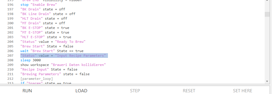
You can use the read State Property in a Wait or if-endif Statement to do something when the button is click to True. You must use Script Code to turn any Button back to False. Once set to true by a Click, it will stay True until a Script reset:

"The Button" State = false

This code makes the button act like a Toggle:

"The Button" State = false
[Pump1 ControlOn] // Pump on when Button On Section
sleep 100 // Prevents accidental double click of Button
wait "The Button" state == true // Wait till Button Clicked
if "The Button” state == true
"Pump 1" State = True // Turn on the Pump
"The Button" State = false // Reset Button to false
goto " Pump1 ControlOff"
endif
[Pump1 ControlOff]
sleep 100 // Prevents accidental double click of Button
wait "The Button" state == true // Wait till Button Clicked
if "The Button" state == true
" Pump 1" State = False // Turn off the Pump
"The Button" State = false // Reset Button to false
goto " Pump1 ControlOn"
endif


Switches

switches.png


Switches have a State property which can be read or written.

Read:

New bool x

x = “Switch 1” State

Set:

“Switch 1” State = False

A Switch has a slide bar that you may click or Slide from Off (False) to On (True) then Back to Off (False). The Bar Changes Color when it is “On”

You can use the read State Property in an if-endif Statement to do something when the switch is slide to True or False.


if "The Switch” state == true
"Pump 1" State = True // Turn on the Pump
else
"Pump 1" State = False // Turn off the Pump
endif
 
Thanks, we'll review ways to make the manual clearer. Also, I accidentally reversed latched and momentary above - now fixed it.

Also, @oakbarn, your script isn’t quite right as you wouldn’t check the state of the button immediate after waiting on it - it will always resolve to a true. In my script above, after the wait, the digital output device’s state is checked in order to invert it.
 
Last edited:
covering several topics in the last few posts:

I have a bootup script that starts when BC starts, it enables all the temp sensors and non-hazardous items. It also monitors a switch and a button. The switch acts as a safety that must be switched before the button press will start the process script. (the order and timing of setting and checking may look weird to those familiar, but I tried a bunch of variants and this one worked pretty good). the switch will be either replaced or paired with a physical momentary lever and the button with a green button with a guard. hold the lever, press the switch and stuff starts happening...

The continuous loop also monitors the state of the script and sets a digital out called 'Running' to either true or false, this is displayed in the HMI and lights up a pole light to show the script is running, If I pause the script for some reason (tweaking or troubleshooting) the fact that the script is running or not is very noticable, which is great when your state changes, actions, and safeties run in that script... It would probably be best to put some safeties in the continually running script also....


Code:
[initialize]
// ensure script is stopped on powerup
stop "Still Run Script"
stop "Timer 1"
stop "Total Runtime"
reset "Timer 1"
reset "Total Runtime"
// ensure switch is off
"Switch 1" State = false
"Bain Marie" Enabled = true
"Boiler Temp" Enabled = true
"Vapor Temp 1" Enabled = true
"Vapor Temp 2" Enabled = true
"Vapor Temp 3" Enabled = true
"PC Water IN" Enabled = true
"PC Water OUT" Enabled = true
"PC HX Return" Enabled = true
"RC Water IN" Enabled = true
"RC Internal" Enabled = true
"Running" Enabled = true

[start]
// ensure button is off
"Start Still Run" State = false
sleep 100
if "Switch 1" State == true
 if "Start Still Run" State == true
  "Switch 1" State = false
  start "Still Run Script"
 endif
endif
if "Still Run Script" State != running
"Running" State = off
endif
if "Still Run Script" State == running
"Running" State = on
endif
//"Start Still Run" State = false .
goto start
 
OK... been promising long enough, time to stop with words and get down to actions. BruControl v1.1 Release Candidate has been posted on the download page. Licensed users will receive an email with the direct link.

Please read the Release Candidate Notes and follow the directions - especially the backup instructions! Also, please email any issues rather than post them in this thread.
 
Back
Top