BruControl: Brewery control & automation software

Homebrew Talk - Beer, Wine, Mead, & Cider Brewing Discussion Forum

Help Support Homebrew Talk - Beer, Wine, Mead, & Cider Brewing Discussion Forum:

This site may earn a commission from merchant affiliate links, including eBay, Amazon, and others.
Obviously something is not connecting. The probable terminals are the 2x3 header. You should check that you have it through the correct holes and that it is fully seating on the MEGA's pins (that central 6 pin "ICSP header"). I wish you had sent me the screw shield - I could have debugged the whole thing!

I will check again but I was able to slide the header up and down on the pins from nearly unseated to fully seated with the screw shield on, so I believe they are in place properly. Can the shield be grounding out these pins in some fashion if there was a defect? I could check for continuity as well perhaps. Yeah, I didn't know at the time that it was the screw shield that was the variable. Once I used V44 firmware, it flashed and configured just fine and worked but once installed in the cabinet with the shield, nothing. That being said, the fact that the ethernet shield powers up, shows connectivity and activity lights, does that jive with a pin problem on the 2x3 header?

Update. I checked continuity of the 2x3 header and I get all six pins passing properly from the controller, through the screw shield, through the ethernet shield and to the stacking pins on the top of the ethernet shield. That to me confirms that the header is installed properly. The pins are also aligned properly through the screw shield such that the ethernet shield is installed in the proper locations on the screw shield (pins and headers align).
 
Last edited:
https://www.adafruit.com/product/3382
says "Power the METRO M4 with 7-9V polarity protected DC "

But https://learn.adafruit.com/adafruit-metro-m4-express-featuring-atsamd51?view=all

says "The DC Jack is a 5.5mm/2.1mm center-positive DC connector, which is the most common available. Provide about 6V-12V here to power the Metro."


Can we run it on 12v or not?

same question with the grand central...


that name... LOL... anyone remember this?
0
9e1b23126a4636d468879090337e304c.png

That voltage regulator has a max input of 20V, so yes you can power it with 12V.
 
It looks like the M4 uses the same three terminal linear regulator to get from the barrel connector input to 5VDC as was used on the UNO. Linear regulators are basically toasters - they turn excess voltage into heat - so the larger the differential from IN to OUT the hotter the regulator will run.

While that regulator is touted as handling 7 to 12V input as used on the Uno, my experience with the Uno-class boards is 7.5V is inadequate for designs sporting additional loads - like an LCD, wifi/BT adapter, relay module, etc - while 12V results in excessive power dissipation at the regulator. 9V is the sweet spot...

Cheers!
 
I will check again but I was able to slide the header up and down on the pins from nearly unseated to fully seated with the screw shield on, so I believe they are in place properly. Can the shield be grounding out these pins in some fashion if there was a defect? I could check for continuity as well perhaps. Yeah, I didn't know at the time that it was the screw shield that was the variable. Once I used V44 firmware, it flashed and configured just fine and worked but once installed in the cabinet with the shield, nothing. That being said, the fact that the ethernet shield powers up, shows connectivity and activity lights, does that jive with a pin problem on the 2x3 header?

Update. I checked continuity of the 2x3 header and I get all six pins passing properly from the controller, through the screw shield, through the ethernet shield and to the stacking pins on the top of the ethernet shield. That to me confirms that the header is installed properly. The pins are also aligned properly through the screw shield such that the ethernet shield is installed in the proper locations on the screw shield (pins and headers align).

It might be difficult to check proper continuity when there are other circuits involved, and this may not rule out short circuits. It is possible that the terminals in the headers are broken and not connecting too. Obviously it worked when we sent it out, but something has changed along the way. I think the E/F firmware versions may have confused the issue.

If you like, return the whole assembly and I'll either fix it or replace the screw shield. Alternatively, buy a screw shield and replace it yourself.
 
It looks like the M4 uses the same three terminal linear regulator to get from the barrel connector input to 5VDC as was used on the UNO. Linear regulators are basically toasters - they turn excess voltage into heat - so the larger the differential from IN to OUT the hotter the regulator will run.

While that regulator is touted as handling 7 to 12V input as used on the Uno, my experience with the Uno-class boards is 7.5V is inadequate for designs sporting additional loads - like an LCD, wifi/BT adapter, relay module, etc - while 12V results in excessive power dissipation at the regulator. 9V is the sweet spot...

Cheers!

power dissipated by the regulator is I = W / (Vin-Vout)

My sunfounder mega has the markings RAK 117-5, and not sure what that is, but from reading, I think the regulator can dissipate 2W, so I = 2 / (Vin-Vout)

– 12 V Power Supply: I = 2 / (12-5) = 2 / 7 = 285mA

– 9V Power Supply: I = 2 / (9-5) = 2/4 = 500mA

– 7 V Power Supply: I = 2 / (7-5) = 2/2 = 1A


I guess we will have to see the specs on the next gen board's power regulator IC's, and see what current I am drawing, but most of my loads are high impedance with just a couple SSR's connected directly.. I am pretty sure I am under 100mA
 
It might be difficult to check proper continuity when there are other circuits involved, and this may not rule out short circuits. It is possible that the terminals in the headers are broken and not connecting too. Obviously it worked when we sent it out, but something has changed along the way. I think the E/F firmware versions may have confused the issue.

If you like, return the whole assembly and I'll either fix it or replace the screw shield. Alternatively, buy a screw shield and replace it yourself.

Yeah I have made the decision to simply use the serial connection at the moment and just move on. I can use that and it has worked perfectly so far. At some point I need to move forward and get this thing done so I can move on to plumbing, scripting, testing, and brewing :). I might mess around with a new screw shield but you need not worry about this, I'm sure everything worked properly when you sent it out. There are always a lot of variables such that I can't say with confidence that I have fully identified them all. No worries there.

During the day, I'm used to working with more "industrial" systems, like DeltaV, Wonderware, and some other proprietary control systems. I'm not an automation guy but I do get in under the hood on occasion. I mean I get it, these Arduino controllers are only $20 but the controllers and shields are all a bit "looser" in their standards and I am simply not used to that. Stupid simple stuff just works in those environments partially because of those tighter standards but it is also glacially slow to evolve.

I look forward to the next release and the integration the White Box Labs tentacle for pH/DO and of the Tilt hydrometer.
 
Absolutely correct and fair comments. These $15 boards will not give you industrial level control. You can get it (or in the direction), but pay more... for example: https://www.industrialshields.com/shop/category/ethernet-plc-1

That said, we are dabbling with hardware. A few posts up we showed some proto work as proof of concept. We've updated the design and will post up some looks again soon. Need to test it, but this could fit the bill, with a reasonable price point.


I have looked at those but I wasn't exactly sure if the firmware would work on it. Is it just a MEGA 2560 R3 with shields and other things already on it more or less? If so, it kind of feels like old tech with a new wrapper. You would still have the limited memory for example. I do look forward to the stuff you are working on and perhaps it would be a nice upgrade path at some point for folks with the MEGA 2560.

So much of the Arduino marketplace is either discontinued or out of stock, etc. I find that odd and a little concerning with regards to the health of ecosystem but I'm not really plugged in so I may just not be aware enough.

In any event, the flexibility of this stuff and the low cost, even with the frustrating stuff, the pain in the ass 3.3v vs. 5v logic, is still the best thing out there in my opinion. Like you, I was a BCS 460 user but was frankly tired of the lack of flexibility.
 
^That^ board evidently uses a switching power supply for the 5V rail. You can see the big inductor just to the right of the 2-screw header.

power dissipated by the regulator is I = W / (Vin-Vout)[...]

PD = ((VIN − VOUT) × IL ) + (VIN × IG)

But the actual limit for the LM117 and similar LDO regs is a function of how well the regulator is thermally managed which can be problematic for a SOT package...

Cheers!
 
^That^ board evidently uses a switching power supply for the 5V rail. You can see the big inductor just to the right of the 2-screw header.


PD = ((VIN − VOUT) × IL ) + (VIN × IG)

But the actual limit for the LM117 and similar LDO regs is a function of how well the regulator is thermally managed which can be problematic for a SOT package...

Cheers!

different calculation, you are calculating watts, I was calculating milliamps from watts...

Edit: here is a GREAT read:
Feeding power to Arduino: the ultimate guide
 
it probably provides protection for inputs and outputs as well, along with being able to be powered by 24VDC..

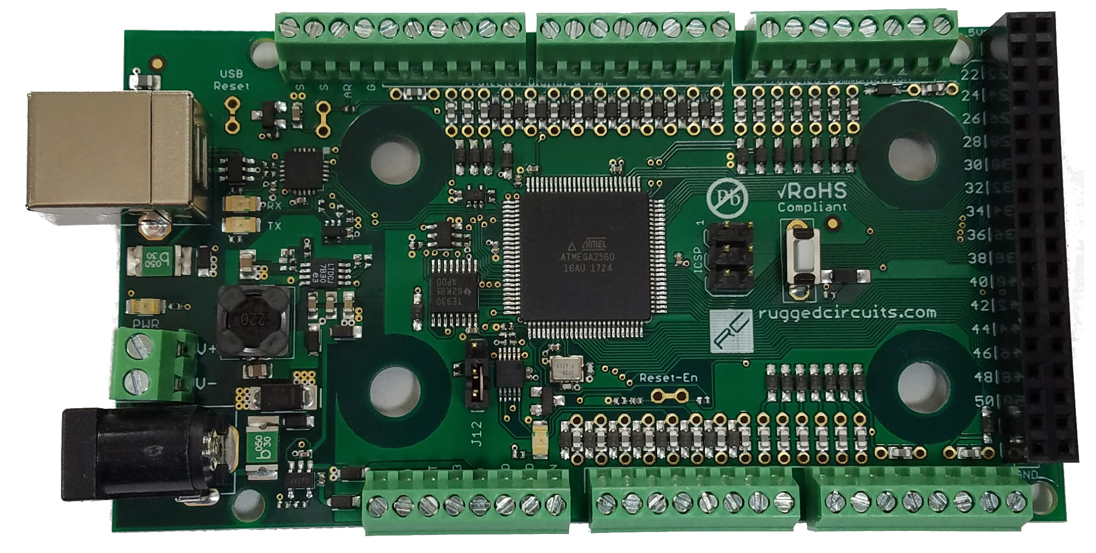
There are some less expensive options made in the US, but hey do not have the true 0-10V inputs and outputs and the nice PLC type case https://www.rugged-circuits.com/microcontroller-boards/rugged-mega-st-screw-terminal
MEGA+ST.png


I found that one after coming across this good read: https://www.rugged-circuits.com/10-ways-to-destroy-an-arduino/

Oh I like the look of some of those. So any of these 2560 based cards will work with V44 firmware?
 
Well I got one of these RobotDyn MEGA 2560 w/built in ethernet today. The controller flashes normally and network setup worked perfectly (v.44 "FR" firmware). The caveat is that the firmware doesn't seem to be working quite right with the ethernet portion of it. The card just by itself, powered by either USB or 12 VDC to Vin, and there is no ethernet "link" or "activity" lights illuminated on either the controller card or my switch (on the UniFi Switch 24 POE-250W itself or in the UniFi controller). It looks like some work may be needed to get it working. The serial connection works fine however, with just the limited testing I have done thus far.
 
Check the specs to see if it is connected to the SPI bus onboard. If not... then not.

It says it is.

"W5500 Ethernet
WizNet W5500 is a TCP/IP embedded LAN Ethernet controller. It provides TCP/IP Stack, 10BaseT/100BaseTX Ethernet with full or half-duplex, MAC and PHY. W5500 is using a highly efficient SPI protocol, with 80 MHz clocks for high-speed connectivity to Atmega2560."
 
Please try v43 but F only, not FR.

There does not appear to be an improvement but as per before, I cannot get any response in Termite when I try to setup the network settings of the controller with v43 firmware. So v43 F is not getting a response in Termite but v44 F does and works as expected. Neither has any response from the ethernet port on the controller. No link or activity.
 
Well, with all due respect, you haven't had much luck communicating, which leads me to continue to believe something is wonky with your computer or drivers. Also, I wouldn't give much credence to the indicator lights. Blink or no blink - we care about communication.

That said, try v44 again, and when you go into network setup, enable DHCP. Disconnect, then reconnect the connection (using the button in Termite). This will reset the interface. Now enable debug mode (%1&14;) and see if it reports a proper IP address.

If it does, ping it from a computer. If that works, connect BruControl.
 
Indeed I have not had total success with ethernet thus far but I do get v44 firmware to work all the time on two of the SunFounder MEGA controllers with an ethernet shield. By that I mean the same switch, cables, power supply, etc. (granted, sans screw shield). I should have been clearer in that my report of a lack of connectivity was also based on confirmation from my switch that no communication had been established between the controller and the switch and also the output of some debugging (%1&14; ). With DHCP set in the v44 firmware, it gets no IP address (0.0.0.0) after disconnection/reconnection/resetting power (the previous SunFounder MEGA with the shield does get an IP, again sans the screw shield). The DHCP server (UniFi Security Gateway 4P) is not handing out an IP address to the new integrated controller/shield due to no connectivity. Quite literally all indications are that the integrated Wiznet 5500 is simply not powered up for some reason. A few random times I have seen one or two of the lights on the RJ45 port illuminate for a split second during power up. A static IP with a properly set MAC, SM, and gateway also does not change anything.

I alluded to this above but the new controller does use a different USB-UART converter than the SunFounder version. It uses the CP2104 chipset from Silicon Labs. I am currently using the Silicon Labs driver 6.7.4.261 from 9/19/2016. I can't speak to the fitness of this driver for what I am doing but it flashes both v43 and v44 correctly 100% of the time thus far, just that v43 network setup fails in Termite (as it does on the SunFounder version). Just to be thorough, this is all true for v43 and v44 firmwares in the "E", "ER", "F", and "FR" versions. I have tried them all.

I just threw a quick sketch at it from the Arduino IDE and the integrated ethernet chip comes on, indicates a link and activity properly, gets an IP address, and works as expected. So I know the controller is good, the cabling is good and it plays nicely in the network I have it attached to. It just doesn't do so with the BruControl firmware. As soon as I flash back to BruControl (v44) the ethernet goes out.

That all being said, I just found this about the card and perhaps that is missing in the BruControl firmware but I am not sure as I don't think I can look under the hood to see.

"Both W5500 and SD card communicate with ATmega2560 via SPI bus. Pin 10 and pin 4 are chip Selection pins for W5500 and SD slot. They cannot be used as general I/O."
 
Last edited:
I thought I saw somewhere it was using pins 10, and the lows 50’s which is consistent with normal cards.
 
No worries. I'm just going to put it aside and revisit it if the card can be made to work. I figured I would give it a try. I mentioned the controller above in this thread, so I just wanted others to know if it was or was not fully functional with BruControl firmware right out of the box. At the moment it appears it is not due to the non functional integrated ethernet. This was a fun diversion but now it is back to some more wiring...
 
Last edited:
Ok... so I am either failing for something I keep overlooking or I may have found a bug...
Example:

[mash_step1]
if "Mash Rest 1" state == true
stop "Mash Timer"
reset "Mash Timer"
restart "Mash Timer"
stop "Step"
reset "Step"
"MT out" value = 50
"MT IN 1" state = on
"MT IN 2" state = on
"MT Pump" State = on
"Mash Control" Enabled = true
"Mash Control" MaxOutput = 100
"Mash Control" Target = MashStep1Temp
HLTControl1 = "Mash Control" target + 12
start "Herms Control"

[loop0]
if "Mass Flow 2 Flow" value < 1
"Stuck Mash" active = True
endif

if "HLT 1" value > HLTControl1
"Mash Control" MaxOutput = 0
else
"Mash Control" MaxOutput = 100
endif

if "mash/sparge in" Value >= MashStep1Temp
restart "Step"
goto timer1
endif
sleep 3000
goto loop0

[timer1]
wait "Step" value >= MashStep1Time
stop "Herms Control"
goto mash_step2
endif


This fails with Output [ERROR: 'end' statement without preceding conditional]

So the endif at the end, does not see the if in the start..

Ok so, If I start removing the if scripts in the statement, it passes.. like this.

[mash_step1]
if "Mash Rest 1" state == true
stop "Mash Timer"
reset "Mash Timer"
restart "Mash Timer"
stop "Step"
reset "Step"
"MT out" value = 50
"MT IN 1" state = on
"MT IN 2" state = on
"MT Pump" State = on
"Mash Control" Enabled = true
"Mash Control" MaxOutput = 100
"Mash Control" Target = MashStep1Temp
HLTControl1 = "Mash Control" target + 12
start "Herms Control"
endif


So then that tells me my if scripts within the script are broke. So lets break those down.

[loop0]
if "Mass Flow 2 Flow" value < 1
"Stuck Mash" active = True
endif

if "HLT 1" value > HLTControl1
"Mash Control" MaxOutput = 0
else
"Mash Control" MaxOutput = 100
endif

if "mash/sparge in" Value >= MashStep1Temp
restart "Step"
goto timer1
endif
sleep 3000
goto loop0

[timer1]
wait "Step" value >= MashStep1Time
stop "Herms Control"
goto mash_step2


Running this script alone yields a flawless pass

new value HLTControl1
new value MashStep1Temp
new time MashStep1Time
MashStep1Temp = 131
MashStep1Time = 0:01:00
HLTControl1 = "Mash Control" target + 12
[loop0]
if "Mass Flow 2 Flow" value < 1
"Stuck Mash" active = True
endif

if "HLT 1" value > HLTControl1
"Mash Control" MaxOutput = 0
else
"Mash Control" MaxOutput = 100
endif

if "mash/sparge in" Value >= MashStep1Temp
restart "Step"
goto timer1
endif
sleep 3000
goto loop0

[timer1]
wait "Step" value >= MashStep1Time
stop "Herms Control"
goto mash_step2

Output = [Started]


However when the switch is added it fails.

new value HLTControl1
new value MashStep1Temp
new time MashStep1Time
MashStep1Temp = 131
MashStep1Time = 0:01:00
HLTControl1 = "Mash Control" target + 12
if "Mash Rest 1" state == true
[loop0]
if "Mass Flow 2 Flow" value < 1
"Stuck Mash" active = True
endif

if "HLT 1" value > HLTControl1
"Mash Control" MaxOutput = 0
else
"Mash Control" MaxOutput = 100
endif

if "mash/sparge in" Value >= MashStep1Temp
restart "Step"
goto timer1
endif
sleep 3000
goto loop0

[timer1]
wait "Step" value >= MashStep1Time
stop "Herms Control"
goto mash_step2
endif


Output = [ERROR: 'end' statement without preceding conditional]

So lets break it down super simple.
[loop0]
if "Mass Flow 2 Flow" value < 1
"Stuck Mash" active = True
endif
sleep 3000
goto loop0


Output = [Started] So thats a pass.

Now lets add another if

if "Mash Rest 1" state == true
[loop0]
if "Mass Flow 2 Flow" value < 1
"Stuck Mash" active = True
endif
sleep 3000
goto loop0
endif


Output = [ERROR: 'end' statement without preceding conditional] and fails


This is just one example, I can use any switch, and as soon as I nest another if in there it fails. So either I am doing something wrong on the whole, or this is a bug.


I'm not crazy... right?
 
Last edited:
[mash_step1]
if "Mash Rest 1" state == true
stop "Mash Timer"
reset "Mash Timer"
restart "Mash Timer"
stop "Step"
reset "Step"
"MT out" value = 50
"MT IN 1" state = on
"MT IN 2" state = on
"MT Pump" State = on
"Mash Control" Enabled = true
"Mash Control" MaxOutput = 100
"Mash Control" Target = MashStep1Temp
HLTControl1 = "Mash Control" target + 12
start "Herms Control"

[loop0]
if "Mass Flow 2 Flow" value < 1
"Stuck Mash" active = True
endif

if "HLT 1" value > HLTControl1
"Mash Control" MaxOutput = 0
else
"Mash Control" MaxOutput = 100
endif

if "mash/sparge in" Value >= MashStep1Temp
restart "Step"
goto timer1
endif
sleep 3000
goto loop0

[timer1]
wait "Step" value >= MashStep1Time
stop "Herms Control"
goto mash_step2
endif


The switch encapsulates the whole step. If Mash Rest 1 switch is on, do it. If not move on.
 
I think this should skin the cat. Not sure what is after this code in the script, but you may be able to remove the whole [end_mash_step1] section and goto mash_step2 instead.

[mash_step1]
if "Mash Rest 1" state == false
goto end_mash_step1
endif

stop "Mash Timer"
reset "Mash Timer"
restart "Mash Timer"
stop "Step"
reset "Step"
"MT out" value = 50
"MT IN 1" state = on
"MT IN 2" state = on
"MT Pump" State = on
"Mash Control" Enabled = true
"Mash Control" MaxOutput = 100
"Mash Control" Target = MashStep1Temp
HLTControl1 = "Mash Control" target + 12
start "Herms Control"

[loop0]
if "Mass Flow 2 Flow" value < 1
"Stuck Mash" active = True
endif

if "HLT 1" value > HLTControl1
"Mash Control" MaxOutput = 0
else
"Mash Control" MaxOutput = 100
endif

if "mash/sparge in" Value >= MashStep1Temp
restart "Step"
goto timer1
endif
sleep 3000
goto loop0

[timer1]
wait "Step" value >= MashStep1Time
stop "Herms Control"
goto mash_step2
[end_mash_step1]


AHA, thats it.. I will customize it a tad, but thats what I was overlooking!
Thanks!
 
Back
Top