• Please visit and share your knowledge at our sister communities:
  • If you have not, please join our official Homebrewing Facebook Group!

    Homebrewing Facebook Group

BruControl: Brewery control & automation software

Homebrew Talk

Help Support Homebrew Talk:

This site may earn a commission from merchant affiliate links, including eBay, Amazon, and others.
For anyone having EMI issues I highly encourage you to read this manual from Allen-Bradley cover-to-cover.

https://literature.rockwellautomation.com/idc/groups/literature/documents/rm/gmc-rm001_-en-p.pdf

After reading it, I changed a few things in my panel and it has been rock solid ever since. Here were my biggest lessons.

1) I use MeanWell DR-120-24 which has a metal case. The case is grounded via the din rail to the enclosure star point. What I did not know is that the DC - terminal is tied to the ground internally so when I tied my DC- Bus to Earth ground I established multiple ground loops. Goes without saying that your PSU may be differently wired but if issues persist worth checking.

2) Classify power carrying wires as dirty or clean. Doesn't matter if they carry AC or DC, high voltage or low if they are dirty they are dirty, and need to be physically separated (industry standard is ~6" free air space) or shielded from the clean ones. I don't have, nor want, a large enough panel to leave 6" of space and the thought of rewiring with heavy gauge shielded wires was a non-starter. So I installed these nifty wire tray shields made by Panduit. They provide the same effective air space without any actual space!

3) All switching PSUs (99% of the DIN rail ones we all use) generate a ton of noise by nature. Most have some basic filter on the output to eliminate +90% but some will slip through along with any induced noise along the wire run. Treat these wires as dirty and use a second filter to generate clean DC power for sensitive electronics (MEGA and sensors) and use the unfiltered side for everything else. This includes devices such as relays, solenoids, contactors and pumps even if flyback diodes, RC Snubbers etc are installed.

I think this third point is REALLY solid. There is no doubt in my mind this is where most noise problems come from. Do you have any recommended inline noise filters?
 
I had a hard time getting termite to actually respond as well, it worked the very first time I tried it but then would not respond when I tried again until I reloaded the firmware on the mega again and waited a while. I had a hard time getting my router to communicate with my mega/wiznet (tried static and dhcp and found the MAC address was the issue) so I had tried changing the ip address many times and found there was sometimes a very long delay or took multiple attempts before termite would display the network configure script.

Thanks. We'll figure it out. We'll check the startup sequence and look for where a hangup might occur.
 
@BrunDog - are there certain functions or ways to do functions that offload more to the interface hardware and do less in the script? If so, do you have examples? To clarify, controlling temp of a 'Digital Output' with a script would definitely be in software on the BruControl PC, no 'smarts' are programmed into the Arduino... But with a 'Hysteresis Output' using 'Target' and 'On Offset' is all the processing offloaded to the interface hardware and BC just changes parameters if needed? if the temp and output are on the same interface, what is BC doing and does hysteresis continue if communication is interrupted?

On the same line of thought, I have a general idea of the difference between a soft button in a workspace and a Digital Input displayed in a workspace... could you explain more of the differences to us, especially how a short or long momentary press is handled in an 'if loop' that has a 500ms pause in it?

We built the combination of scripting and internal interface functions to balance speed, memory, safety, etc. PID, Hysteresis, and Duty, and one-shots run their cycles internally so they are time accurate. We will be adding a "Deadband" which will do likewise. These functions are very structured and run autonomously (to answer the last question in your first paragraph, yes... hysteresis continues.)

From there, scripting gives the user a lot of control and flexibility. But if communication ceases, the script steps will not get executed at the interface level until communication reconnects (it is up to the user to build the script such that mission critical safety is maintained, and communication checking can be part of the script.). We just can't offload every situation to the interface - at some point you lose flexibility and interface memory is always a concern.

A soft button in a workspace is a user control - the user clicks it to drive a state in a script. A Digital Input is a read-only status of the digital I/O pin it references. That could be a physical button, for example, which is wired to the input pin.

I'm not sure your last question. If you need it to be more responsive, change the pause to a much smaller number, say 25 ms. You just don't necessarily want the CPU to freewheel, and 25 ms is a blink to us humans but an eternity to a 1.5 GHz CPU.
 
Sadly, the brand new MEGA 2560 is showing the same problem. Termite simply provides no return once any command is sent over, even though the controller flashes the communication light showing the command was received. Flashing, as always, works fine but networking setup fails. As network setup cannot be performed, no MAC address appears to be present on the shield and thus no IP address can be assigned by my DHCP server. Of course static can't be set either due to a lack of response. Given the number of controllers, network shields, computers, versions of Windows, drivers, and serial cables tested with all tests resulting in no response, the only item unchanged so far is the firmware. I will try a few more things but I don't expect much improvement.

Update: OK, so real odd but if I press the "SW1" switch on the Ethernet shield while the Termite program is open and the serial connection (USB) connection is still up, the shield responds in Termite and the 10s countdown starts and everything works normal.

Update II: This doesn't work anymore...grr.
 
Last edited:
I dont know if you ever sorted your issue out but I have my panel wired like yours only using small mechanical relays to control allen bradley 24v coil contactors though on top of the ssrs. I fried an Arduino because I had too much load on the outputs amp wise.. I dont remember the MA outputs for each output and the combined total but its not much and too much at once will cause the arduino to overheat. If you go back and read my earlier posts here you will see I had a lot of the same issues as you.. lots of noise induced issues. first I was using 240v ac coil contactors which I was able to supress the noise with rc snubbers but then I decided to replace those with UL listed 24v dc coil based contactors and use flyback diodes to stop the noise. I also found I did have a ground loop and the cheap noname red relay board I was using was introducing noise as well (lots of rtd resets and even fried rtd boards)

I thought of ditching the mechanical relays all thogether but needed the NO/NC contacts to prevent having certain elements on at the same time on my limiting power source. everything is working well now and once in a great while I may see a single rtd readout jump when turning on elements but its rare.
Thanks augie. I don't think it was too much current (yet) because I barely had any devices connected to the mega when I killed it. I'll def. keep your advice in mind as I complete my build and have more things connected to the mega. Given that it happened in short order after I turned the contactor for each of my 2 elements on and then off again, I am inclined to believe that this one was a voltage spike caused by those inductive loads.

In much more fun news, I got my my pressure-transmitter volume sensor wired up and calibrated. Thanks for making the spreadsheet for that @BrunDog! A couple of simple measurements of my kettle and the sensor was shockingly accurate on the first calibration run! I only needed to slightly modify the linear offset and the sensor was dead on* after that. FWIW, the etched volume measurements in my Spike kettle were pretty much dead on as well.

*at least to the level of accuracy of my measuring pitcher
 
Sadly, the brand new MEGA 2560 is showing the same problem. Termite simply provides no return once any command is sent over, even though the controller flashes the communication light showing the command was received. Flashing, as always, works fine but networking setup fails. As network setup cannot be performed, no MAC address appears to be present on the shield and thus no IP address can be assigned by my DHCP server. Of course static can't be set either due to a lack of response. Given the number of controllers, network shields, computers, versions of Windows, drivers, and serial cables tested with all tests resulting in no response, the only item unchanged so far is the firmware. I will try a few more things but I don't expect much improvement.

Update: OK, so real odd but if I press the "SW1" switch on the Ethernet shield while the Termite program is open and the serial connection (USB) connection is still up, the shield responds in Termite and the 10s countdown starts and everything works normal.

Update II: This doesn't work anymore...grr.

Man that is something wonky. Try doing the network setup without the shield attached. If it works, once the network parameters are saved, you can power it down, reconnect the shield, then power it up again.
 
Man that is something wonky. Try doing the network setup without the shield attached. If it works, once the network parameters are saved, you can power it down, reconnect the shield, then power it up again.

Well I had some success. I powered down, pulled the ethernet shield and connected back to the controller. Termite was still unresponsive. Flashed over to the serial firmware and like before, Termite returned a quick response. Then I flashed back to "ER" and Termite was still unresponsive. Then I flashed to the "WR" firmware and Termite responded to %0&15;. Flashed one more time to "ER" and Termite finally responded and allowed network setup to complete. I am afraid to try again so I am not sure why this worked or why it didn't before.

Update: Well I can seem to get Termite to get a response every time if the shield is not installed but the shield doesn't seem to be working. In DHCP mode it doesn't get an IP and in static mode Brucontrol can't reach it and it does not respond to pings (maybe it doesn't do that normally). Something is still wonky considering the network setup functioned fine 4 days ago.
 
Last edited:
sounds like the same thing that happened to me, I needed to assign a mac address all FFs wont work I made my own using most of the numbers and letters from another mac of another device and it accepted it on the second attempt and my router then saw it correctly.
 
Oddly enough my shield had a MAC address sticker on the back so I used that. I assumed it was valid but I need to check that. Of course now I can't get Termite to respond anymore....

Update: Finally got Termite to respond after too many to count iterations and flashes but even with a MAC that is for sure correctly generated, the shield is still just sitting there blinking and not responding at it's assign static IP. I just have to walk away...I need a beer.
 
Last edited:
Sounds like the shield is not working right. Are you trying the non-R version of the FW's (aka F, not FR).

Note: All W5500 based boards will have a sticker on it with the MAC address on it. Use that. W5100 boards need a MAC "created". I usually use an arbitrary one, knowing darn well another duplicate MAC will not be on my local network.

I would agree but this is the second shield (one from you and another copy from Amazon) and I find it a bit unlikely that they are both not working correctly unless a bad batch went out globally or something. They are both the W5500 version and I tried both the MAC on the device and a generated one with no success. I even cut the network down to just the controller/ethernet shield, a switch, and the BruControl Windows box, all with static IP's and still nothing. I do have a "complex" for a home installation Ubiquiti setup at the house and just in case I was missing something or somehow port 5000 was getting blocked, I wanted to simply eliminate that chance (even though it work earlier this week :)).

I have tried the non RTD version at some point but I can't recall when in this process and it may have been at the point in time when I could not get Termite to respond. Is there a chance the RTD version is wonky?

Both controllers work fine via the "SR" firmware, if that is any indication of controller fitness.
 
I use a Ubiquiti network as well (USG 3P and a AP-AC-Pro) and no issues with any network (WiFi or Ethernet) boards.

The RTD version uses the same SPI serial bus as the network shield. I suggest you try it without for that reason.

At the end of the day, I still think you should send back a non-working config and let us see if we can duplicate your issue.

I was able to get a non "R" ethernet firmware to load and the network setup to work and still nothing. The logs from the UniFi controller also has not a single instance of the shield mac address in it anywhere. I don't know enough about the Arduino stuff to really speak intelligently about what is going on, so I won't :).

Even more fun, I have figured out that if I flash the controller (ethernet shield installed) with an "E" version (or "ER" for that matter) and run the network setup, Termite still has no response to any commands until I press the ethernet shield button "SW1". Once I press that, a response pops up in Termite. So I have begun starting with a semi-colon command which brings about no response, then a press of the shield button brings up the %0&23; response. Then I issue %0&15; command, no response but when I press the switch, bingo the setup count down beings and setup runs normally. Really strange.

I can send back the mega and the shield if you would like to look into them to troubleshoot. I have a spare now and serial does work so I can use that but I am still wiring my panel and it doesn't really matter yet. I won't be able to do so until the week of the 10th however as I am travelling. You can drop me the shipping info any time it is convenient.
 
I never use termite with the shield on. Also I have 5 w5500 shields here from digikey. I have ordered them at separate times over the last 6 months. Zero came with a MAC address and I just generate one.
 
I never use termite with the shield on. Also I have 5 w5500 shields here from digikey. I have ordered them at separate times over the last 6 months. Zero came with a MAC address and I just generate one.

I am getting the feeling that there is less consistency on the ethernet component front than perhaps we think there is or we hope there would be. I have flashed the controller with and without the shield installed but when the shield is not installed and Termite is not receiving a response from the controller (which is very, very frequent), there is nothing I can do to force the response to come back. Through trial and error (mostly error), I found that I could consistently get Termite to respond by pressing that shield switch (which I assume is a reset button). I can't say what it means or proves however.
 
I never use termite with the shield on. Also I have 5 w5500 shields here from digikey. I have ordered them at separate times over the last 6 months. Zero came with a MAC address and I just generate one.

That is surprising. I think I’ve never seen a 5500 without a MAC. Anyway, it doesn’t matter - this is not the source of anyone’s troubles. I would caution against changing MAC/IP combinations from setup to setup. Once your computer stores this map it will need to be deleted, which I have found only works with an arp edit or reboot.

I’m not sure I understand why a reset press cause the terminal response to show up. I can see the serial buffer getting flushed, but the micro is being reset, so there should not be any ability to continue into the setup.
 
Are you testing without the screw shield?

Also testing with no other devices connected (just USB and Ethernet cables)?

Correct, without the screw shield and with no other devices connected. Just the USB connection to the computer running the flashing program and the ethernet cable (I have tried without it connected as well).
 
That is surprising. I think I’ve never seen a 5500 without a MAC. Anyway, it doesn’t matter - this is not the source of anyone’s troubles. I would caution against changing MAC/IP combinations from setup to setup. Once your computer stores this map it will need to be deleted, which I have found only works with an arp edit or reboot.

I’m not sure I understand why a reset press cause the terminal response to show up. I can see the serial buffer getting flushed, but the micro is being reset, so there should not be any ability to continue into the setup.
My ebay 5500 did not have a mac but I believe its a generic,
 
Sounds like the shield is not working right. Are you trying the non-R version of the FW's (aka F, not FR).

Note: All W5500 based boards will have a sticker on it with the MAC address on it. Use that. W5100 boards need a MAC "created". I usually use an arbitrary one, knowing darn well another duplicate MAC will not be on my local network.

not true.. I ordered these W5500's from mouser, a reputable vendor, and had to create my own mac's, I just took the existing MAC from a device I had and incremented it by 1 and 2 for my 2 W5500's
 
Just received some Ethernet W5500's from Seeedstudio. They have MAC sticker on the bottom side. Just FYI. Clearly not all vendors are including them. I thought I read a while ago it was a requirement of the 5500 chipset. Anyway, so be it - no biggie creating your own MAC.
 
So I need script help. My brew script is written to enable my sensors, valves, pumps. I have the script set to autostart when brucontrol loads. However, the script doesn’t enable my device elements unless I manually stop the script and then restart it. I modeled the setup phase off of @BrunDog script. I tried a sleep but that didn’t help. Any suggestions?
 
Yes, please post it.

It is possible the script is executing before the interface is connected upon start-up. You mentioned a sleep statement which makes sense, but we can use the ‘connected’ property to check for the interface first, then go from there.
 
Certain devices, like inputs such as temp probes are always enabled. You can check to make sure they are connected by checking their connection:
Code:
[CheckConnection]
if "Temp1" Connected == true
goto EnableDevices
endif
sleep 1000
goto CheckConnection

[EnableDevices]
...   // start your enable sequences here
 
Ugh, sorry. Back up often. You can cut and paste scripts from the editor to a text editor by using CTRL+A to select all then CTRL+C to copy.

I know it doesn't help now but 1.1 will have automatic configuration backups.

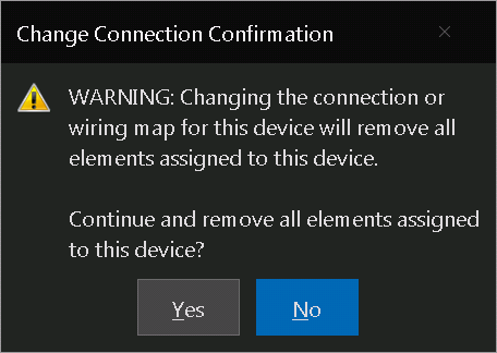
Does a connection from ethernet to serial really need to wipe our all devices? Is there a way to work around this?
upload_2018-12-3_5-34-30.png
 
If only someone made a 'full' w5500 shield that allowed the din rail screw shield and the W5500 to be used at the same time.. or a W5500 screw shield... yes, that is the ticket!
they do make din rail mounts for the arduino that allow the use of this shield.
http://rover.ebay.com/rover/1/711-5...0001&campid=5338413729&icep_item=292465739698


thats what I use but I also wish there was a more convenient solution.

I was tempted to try one of these.
http://rover.ebay.com/rover/1/711-5...0001&campid=5338413729&icep_item=332802714761
 
Last edited:
If only someone made a 'full' w5500 shield that allowed the din rail screw shield and the W5500 to be used at the same time.. or a W5500 screw shield... yes, that is the ticket!

Hence the reason we're toying with some custom build DIN Universal shields! There are some pics posted back in this thread - more to come.
 
Does a connection from ethernet to serial really need to wipe our all devices? Is there a way to work around this?
View attachment 600620

The challenge is not the connection type but the wiring map, which are tied in a dependent hierarchy. If you have some XML editing skills, you can simply edit the configuration (.brucfg) file. It is an XML format. Set up both interfaces in BC. Then close BC, backup copy the configuration file (for safety), then edit the original. You will see devices marked out in the beginning with a <Device> tag. Just reverse the details just after this tag and just before it closes. The wiring map must be the same!

Alternatively, email us the configuration file with a note what you are looking to change, and we will edit it for you.
 
Across the load, as close to the load is best, but let’s be practical. Try across the coil first and see if that makes a difference. If it does, then[emoji106], otherwise go across the power lines in the enclosure and see if that helps.
Hi BrunDog,

I'll be back in my panel a bit later today, so I wanted to confirm: for my purposes (suppressing voltage spikes from activating/deactivating contactors) when you say "across the load," you mean to connect one leg of the MOV to the load terminal the other to the neutral terminal across the contactor coil, right?

Thanks again.
 
I use mine in the din screwshield.

yeah, I thought that was a bit involved and would be difficult to use in a production requirement if a spare was ever needed, but gave it a shot right now, and it worked... my eyesight is getting worse, and I went to unsolder the header with the two pins that needed to be longer, I should have just pried the plastic off and swapped the 2 pins.. next time... and I can make a video anyway, it works and looks great... still puzzled why pieces that don't fit logically even exist...
IMG_20181203_172801.jpg

now for a din adapter for my sainsmart 16 channel relay board..
 
Back
Top