You are using an out of date browser. It may not display this or other websites correctly.
You should upgrade or use an alternative browser.
You should upgrade or use an alternative browser.
BruControl: Brewery control & automation software
- Thread starter BrunDog
- Start date

Help Support Homebrew Talk:
This site may earn a commission from merchant affiliate
links, including eBay, Amazon, and others.
Gameface
Well-Known Member
Maybe it's time to try a different MEGA and see if that does the trick?Has anyone experienced the ground and 5v pins being tied together on the mega? I wonder if that might be causing my noise and possibly not being able to drive the mega and the shield with 12v.
Maybe it's time to try a different MEGA and see if that does the trick?
Just ordered one! It will be here Monday.
Has anyone experienced the ground and 5v pins being tied together on the mega? I wonder if that might be causing my noise and possibly not being able to drive the mega and the shield with 12v.
If these are tied together it won’t work at all. How are you assessing this?
Super simple question, but what's everyone's preferred method for connecting the wires from the electronic valves to the cable that will go to the enclosure? Buttsplice then cover with shrink tubing? Something else?
I typically extend the wires this way. Solder the wires together, heat shrink each solder joint, then heat shrink the whole assembly. It's clean, reliable, and takes up no additional space.
Die_Beerery
Well-Known Member
- Joined
- Aug 21, 2017
- Messages
- 842
- Reaction score
- 643
+1I typically extend the wires this way. Solder the wires together, heat shrink each solder joint, then heat shrink the whole assembly. It's clean, reliable, and takes up no additional space.

$7.79 ($7.79 / Count)
Craft A Brew - LalBrew Voss™ - Kveik Ale Yeast - For Craft Lagers - Ingredients for Home Brewing - Beer Making Supplies - (1 Pack)
Craft a Brew

$44.99
$49.95
Craft A Brew - Mead Making Kit – Reusable Make Your Own Mead Kit – Yields 1 Gallon of Mead
Craft a Brew

$176.97
1pc Commercial Keg Manifold 2" Tri Clamp,Ball Lock Tapping Head,Pressure Gauge/Adjustable PRV for Kegging,Fermentation Control
hanhanbaihuoxiaoshoudian

$33.99 ($17.00 / Count)
$41.99 ($21.00 / Count)
2 Pack 1 Gallon Large Fermentation Jars with 3 Airlocks and 2 SCREW Lids(100% Airtight Heavy Duty Lid w Silicone) - Wide Mouth Glass Jars w Scale Mark - Pickle Jars for Sauerkraut, Sourdough Starter
Qianfenie Direct

$58.16
HUIZHUGS Brewing Equipment Keg Ball Lock Faucet 30cm Reinforced Silicone Hose Secondary Fermentation Homebrew Kegging Brewing Equipment
xiangshuizhenzhanglingfengshop

$53.24
1pc Hose Barb/MFL 1.5" Tri Clamp to Ball Lock Post Liquid Gas Homebrew Kegging Fermentation Parts Brewer Hardware SUS304(Gas MFL)
Guangshui Weilu You Trading Co., Ltd

$20.94
$29.99
The Brew Your Own Big Book of Clone Recipes: Featuring 300 Homebrew Recipes from Your Favorite Breweries
Amazon.com

$76.92 ($2,179.04 / Ounce)
Brewing accessories 1.5" Tri Clamp to Ball Lock Post Liquid Gas Homebrew Kegging Fermentation Parts Brewer Hardware SUS304 Brewing accessories(Gas Hose Barb)
chuhanhandianzishangwu

$10.99 ($31.16 / Ounce)
Hornindal Kveik Yeast for Homebrewing - Mead, Cider, Wine, Beer - 10g Packet - Saccharomyces Cerevisiae - Sold by Shadowhive.com
Shadowhive

$53.24
1pc Hose Barb/MFL 1.5" Tri Clamp to Ball Lock Post Liquid Gas Homebrew Kegging Fermentation Parts Brewer Hardware SUS304(Liquid Hose Barb)
yunchengshiyanhuqucuichendianzishangwuyouxiangongsi

$159.99 ($26.66 / Count)
3M High Flow Series System BREW120-MS, 5616001, For Brewed Coffee and Hot Tea, Valve-in-Head Design
SpaceCityProviders

$22.00 ($623.23 / Ounce)
AMZLMPKNTW Ball Lock Sample Faucet 30cm Reinforced Silicone Hose Secondary Fermentation Homebrew Kegging joyful
无为中南商贸有限公司
If these are tied together it won’t work at all. How are you assessing this?
I used an ohm meter. The 3.3v did not ohm out to ground, but the 5v pins did. Also, pins 43-46 were not working at all.
You can’t test conductivity this way, because both these pins run through silicon. You’d find different readings when you reverse the probes as a result, too. Best to power the MEGA and read the voltages in these pins, relative to ground.
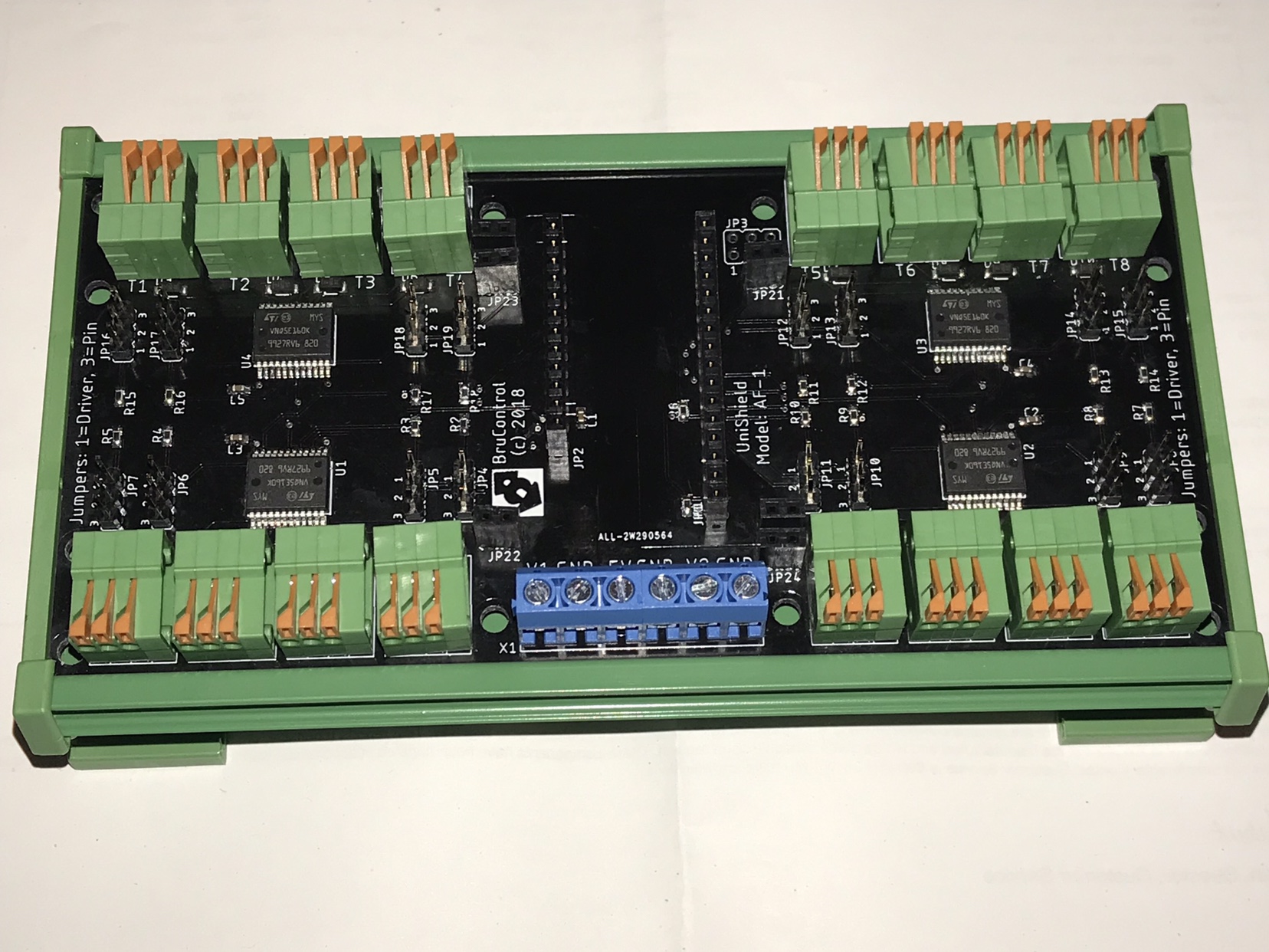
Progress being made... next step is to test.


What is that?
It’s a universal shield with high current outputs. This one is driven by a feather, which you plug in. Proof of concept for now.
VinceBrews
Well-Known Member
- Joined
- Oct 26, 2013
- Messages
- 59
- Reaction score
- 6
I have a flow sensor and a proportional valve. Question: is there a way to have the proportional valve target a flow rate (PID or hysteresis)? When I create the PID or hysteresis devices, I don't see my flow rate as an input. Am I doing something wrong or is the capability just not there?
I'm assuming I'll be able to do this with a script.. but I'm not there yet.
Thanks
I'm assuming I'll be able to do this with a script.. but I'm not there yet.
Thanks
- Joined
- Mar 24, 2016
- Messages
- 558
- Reaction score
- 60
Used BruControl for a real brew this weekend. So far, tickled pink about the performance of the software and very pleased with the performance of my new/interim setup. Still running my old two vessel set up in counterflow HERMs configuration (dual purpose HLT/BK with external heat exchanger), but swapped out the 2 x 120v/1650 watt elements with 2 x 240v/5500 watt ripple elements, changed the MK II pumps for some RipTides for increased head, and replaced the shell and tube exchanger with a pipe-in-pipe exchanger from Stout.
With 11,000 watts and 5 gallons in the HLT, it takes no time to ramp temps at the MLT return. However, what still takes a bit of time is getting the entire MLT up to temp. I put a temp probe at the MLT out and this was the first brew day where I was able to watch this temp real time. The script I wrote looks at the MLT out temp and doesn't start the mash step timer until the MT out temp is within a defined offset from the specified mash temp.
During the mash I'm controlling the elements on the MLT return temp. For anyone else who might run this same configuration, I found that my PID values didn't follow typical guidance. The following worked well.
P=0.5
I=1.0
D=10
I have a flow sensor and a proportional valve. Question: is there a way to have the proportional valve target a flow rate (PID or hysteresis)? When I create the PID or hysteresis devices, I don't see my flow rate as an input. Am I doing something wrong or is the capability just not there?
I'm assuming I'll be able to do this with a script.. but I'm not there yet.
Thanks
Uh-oh! Someone found a ***** in the armor! Indeed, flow-meters are not currently supported as inputs to PID's or Hysteresis devices. We have this on the docket somewhere.
I use a script to do this... I'll post a sample shortly.
augiedoggy
Well-Known Member
I I have what should be a silly question I hope I Finish my fermentation control panel which uses the 6 thermistor bc board and came with the sheet with all the resistor values. however when I enter in those values brew control keeps losing and reconnecting and eventually I get a script error saying the resistor value was too high or too low. I can't remember what I used for the values on my home brewing panel sense I haven't reset that up after the configuration files came corrupt and I lost everything. Am I supposed to enter the resistor values as they were written on that sheet or am I missing something
augiedoggy
Well-Known Member
Btw with a resistor value of 0 and just I Celsius to Fahrenheit conversion I'm reading like 1197゚ right now I don't know if that's an indication of whether or not the hardware is functioning correctly or incorrectly It's strange because it seems to work fine at 0 but as soon as I put in a value in the resistor field it crashes.
Last edited:
so is this a new connection to wiring instead of screw terminal, haven't seen this yet? does it hold well?Progress being made... next step is to test.
I I have what should be a silly question I hope I Finish my fermentation control panel which uses the 6 thermistor bc board and came with the sheet with all the resistor values. however when I enter in those values brew control keeps losing and reconnecting and eventually I get a script error saying the resistor value was too high or too low. I can't remember what I used for the values on my home brewing panel sense I haven't reset that up after the configuration files came corrupt and I lost everything. Am I supposed to enter the resistor values as they were written on that sheet or am I missing something
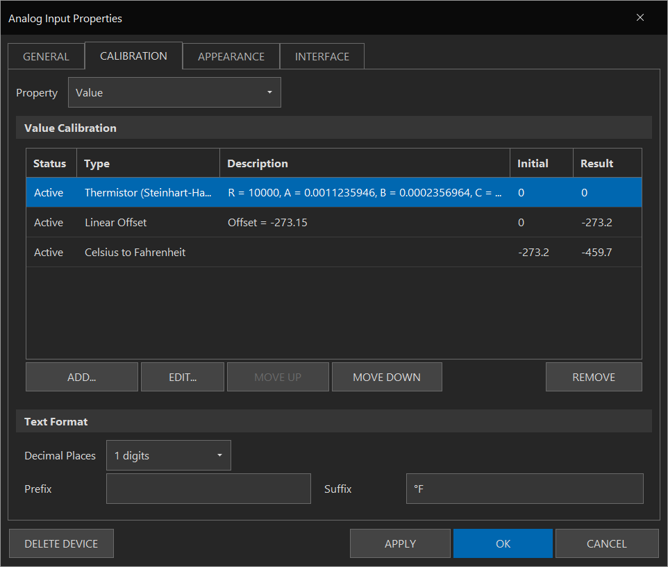
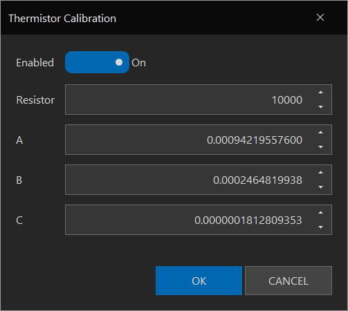
Hmm.. not exactly following you. Here is a thermistor calibration screen shot (ignore the values as the interface is currently off):

so is this a new connection to wiring instead of screw terminal, haven't seen this yet? does it hold well?
These connectors were selected for a few reasons: side entry, current capacity, tool-less design, allow for boards to be stacked above, co$t, etc..
augiedoggy
Well-Known Member
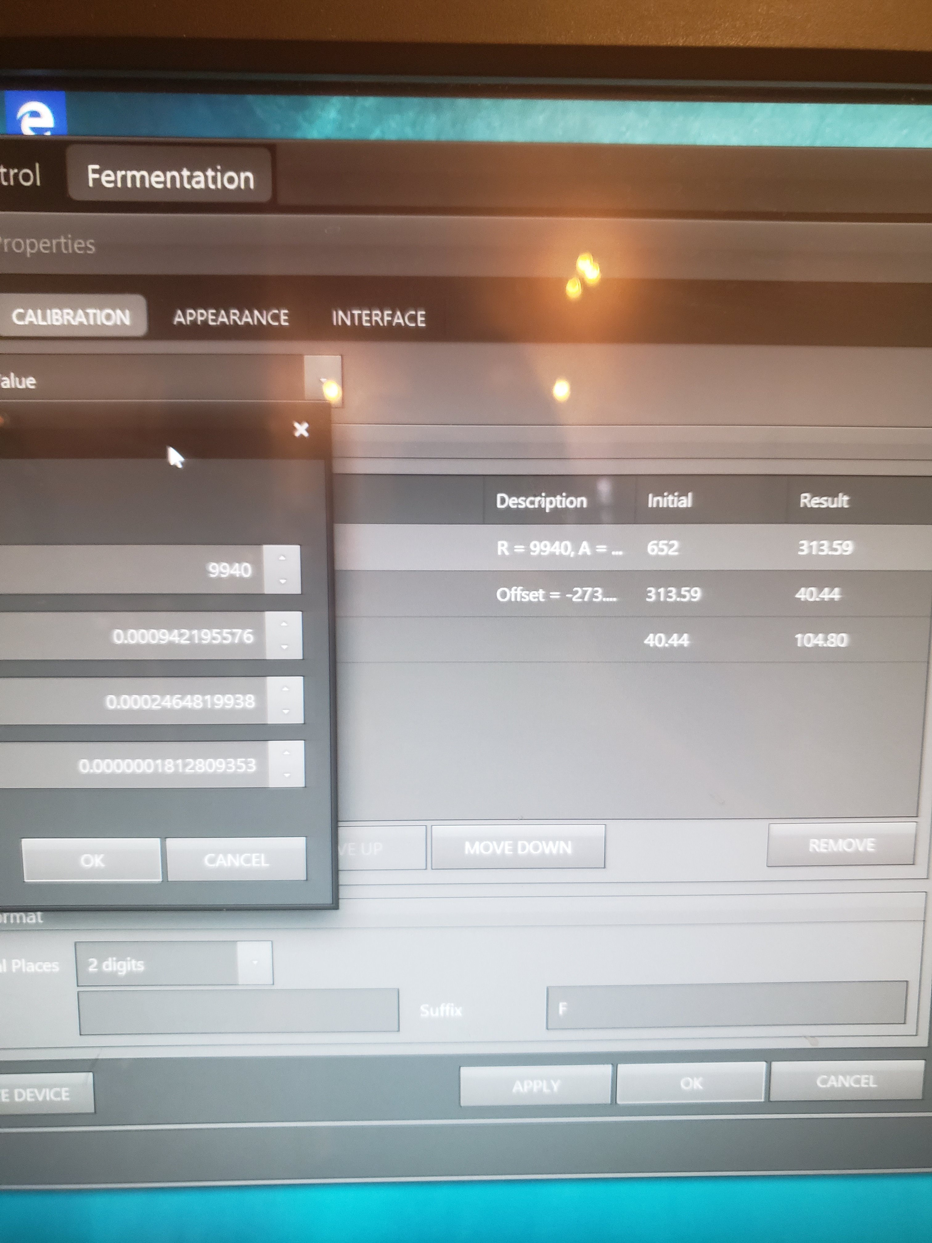
Yes this is what I'm confused about.. I don't remember where all those numbers came from or how to get them. All I have is a resistor value for each on of the thermistor channels(R1-r6) when I put the numbers in (example sheets says 9940 for R1) the software crashes and displays an error box saying the value was too high or too low.Hmm.. not exactly following you. Here is a thermistor calibration screen shot (ignore the values as the interface is currently off):
View attachment 596319
I faintly remember having this issue before.
augiedoggy
Well-Known Member
Nevermind , just found what I missed in the manual
Please share: The error which made it crash (this should NEVER happen and we are obligated to fix these errors). What you had wrong so others can learn.
For the sake of clarity: the three calibrations above are:
1. Thermistor calibration, taking pad resistor and thermistor coefficients as inputs. This results in the temperature in Kelvin.
2. Kelvin -> Celsius conversion (just subtract 273.15 degs).
3. Celsius -> Fahrenheit conversion.
For the sake of clarity: the three calibrations above are:
1. Thermistor calibration, taking pad resistor and thermistor coefficients as inputs. This results in the temperature in Kelvin.
2. Kelvin -> Celsius conversion (just subtract 273.15 degs).
3. Celsius -> Fahrenheit conversion.
Thought of a question that I ran across during my brew day yesterday.
As mentioned above, I use a dual purpose HLT/BK and use the MLT return temp as the control point during the mash. While lautering I would like to begin ramping up to boil and want the PID to read the HLT/BK temp instead of the MLT return temp to prevent boiling before the lauter is complete. I thought I could accomplish this by using the following script
"PID: Elem1" InputPortID = 202
"PID: Elem2" InputPortID = 202
With InputPortID #202 being the port number for the HLT/BK 1-wire temp sensor.
Does anyone know of a different way to switch the controlled input variable on the PID device?
This caused a hangup in my script, but I finished the brew day manually without too much hassle. Still, I'd like to get it resolved so it doesn't happen this upcoming weekend.
augiedoggy
Well-Known Member
I atte
Opted to just input the r1 values and left a-c blank and that causes the crash. I just found a steinhardt calculator and put the values in alo g with the k and F conversions and am getting 101 degrees so I'm still not out of the water.. perhaps the stc1000 temp proves I'm using have some different values I'm missingPlease share: The error which made it crash (this should NEVER happen and we are obligated to fix these errors). What you had wrong so others can learn.
For the sake of clarity: the three calibrations above are:
1. Thermistor calibration, taking pad resistor and thermistor coefficients as inputs. This results in the temperature in Kelvin.
2. Kelvin -> Celsius conversion (just subtract 273.15 degs).
3. Celsius -> Fahrenheit conversion.
Ask and ye shall receive. Here are the coefficients for the STC probes:

And NO... you cannot leave those fields blank!

And NO... you cannot leave those fields blank!
Thought of a question that I ran across during my brew day yesterday.
As mentioned above, I use a dual purpose HLT/BK and use the MLT return temp as the control point during the mash. While lautering I would like to begin ramping up to boil and want the PID to read the HLT/BK temp instead of the MLT return temp to prevent boiling before the lauter is complete. I thought I could accomplish this by using the following script
"PID: Elem1" InputPortID = 202
"PID: Elem2" InputPortID = 202
With InputPortID #202 being the port number for the HLT/BK 1-wire temp sensor.
Does anyone know of a different way to switch the controlled input variable on the PID device?
This caused a hangup in my script, but I finished the brew day manually without too much hassle. Still, I'd like to get it resolved so it doesn't happen this upcoming weekend.
Apparantly there is an issue with InputPortID. It should work... we'll fix it.
augiedoggy
Well-Known Member

Lol you mean it wont automatically figure everything out with just a few sparce pieces of info?Ask and ye shall receive. Here are the coefficients for the STC probes:
View attachment 596328
And NO... you cannot leave those fields blank!
So with those numbers I get
104 degrees at 64 degrees...
The thermisters I'm using are 10k 3435 thermistors and I'm using one on an stc1000 in the interm right now were its reading temps correctly.
Last edited:
Are these thermistors the one's included with the STC1000? That is what I gave you the coefficients for. If they are some other thermistor, they need the correct coefficients. You need the datasheet of the exact thermistor - they are all different.
You can’t test conductivity this way, because both these pins run through silicon. You’d find different readings when you reverse the probes as a result, too. Best to power the MEGA and read the voltages in these pins, relative to ground.
Wanted to give an update. The new mega has all of the ports working and runs stable at 12v. I also installed a 4 channel mosfet board and all of the spikes are now gone! The last issue I have is I also ordered a sunfounder Ethernet shield, but I have to hit the reset button before it works. If I had to guess I would think it’s a startup sequence deal.
By the way, I received the quadzilla today! It looks awesome and doing a leak test now. Do you recommend wiring all 4 elements together?
Good to know! What Ethernet shield (link?)?
Up to you if you want to do all four together or go individual. Given the flexibility in the software, I think you can wire all four together.
Up to you if you want to do all four together or go individual. Given the flexibility in the software, I think you can wire all four together.
augiedoggy
Well-Known Member
yes I've been looking at al the different ones. these are not. But I'm using these with an stc1000 and they are calibrated and reading the correct temp this is what's confusing me. I've tried some coefficients from others like the -40-120degree versions and the members are close.. it reads 59 degrees at 64. I'm going to try some different stc thermisters I haveAre these thermistors the one's included with the STC1000? That is what I gave you the coefficients for. If they are some other thermistor, they need the correct coefficients. You need the datasheet of the exact thermistor - they are all different.
Good to know! What Ethernet shield (link?)?
Up to you if you want to do all four together or go individual. Given the flexibility in the software, I think you can wire all four together.
https://www.amazon.com/dp/B00HG82V1A/?tag=skimlinks_replacement-20
Here is the link.
yes I've been looking at al the different ones. these are not. But I'm using these with an stc1000 and they are calibrated and reading the correct temp this is what's confusing me. I've tried some coefficients from others like the -40-120degree versions and the members are close.. it reads 59 degrees at 64. I'm going to try some different stc thermisters I have
Give me the link to what you have and I will try my best to get you coefficients that are close (and show you how while I'm at it).
Try both the 43.E and 44.E firmware versions. Firmware 43 separate Ethernet libraries for W5100 and W5500 based chips. Firmware 44 has a library where they are combined (even though we published, but I cannot absolutely claim they are cross compatible).
OK, here is a quick demo of the UniShield.
augiedoggy
Well-Known Member
Sorry, Im not trying to put it on you, I should have reread the operator manual before implenting them.Give me the link to what you have and I will try my best to get you coefficients that are close (and show you how while I'm at it).
I bought them almost a year ago and ebay wont let me see the detailes other than "0.5m Wire 5pcs NTC 10K Ohm 1% 3435/3950 Thermistor Temperature Sensor Probe Hot" which doesnt give me the exact temp range. I may just use some other stc sensors I have instead.
On a positive note, we had our first brew session at the brewpub Sunday and brucontrol performed flawlessly...I had unrelated issues with the false bottom and the crush being too fine causing flow issue with the rims but still managed 85% and hit our numbers.
It's all good... just tryna help a man out. 3435 and 3950 are two different animals - we would need to know which you actually have.
These numbers refer to the thermistor's beta coefficient. It is a simpler approximation than the Steinhart-Hart coefficients BC uses, but you can get them close.
If you use an ohmmeter, you can measure the resistance at known temperatures. True "knowns" would be 0 (ice water) and 100 (boiling water at sea level). Other knowns can be measured with a quality temp probe. Put them into this calculator to figure out the SH coefficients: https://www.thinksrs.com/downloads/programs/therm calc/ntccalibrator/ntccalculator.html
Good to know! What Ethernet shield (link?)?
Up to you if you want to do all four together or go individual. Given the flexibility in the software, I think you can wire all four together.
I got the quadzilla installed( currently with wirenuts and electrical tape. It works awesome, but I will have to adjust my rims temperature sensor as the water was steaming and it read 95f lol
Ya something is amiss. Keep in mind 5500W is a LOT of heat in a small cavity. It will heat it REALLY quickly. You must make sure:
1. Don't allow power to it unless you are sure there is adequate flow.
2. Don't allow too much power to it... if Duty Cycle, start really small. If PID put a cap on the max.
3. There is an exit for steam to escape... else bad things can happen!
1. Don't allow power to it unless you are sure there is adequate flow.
2. Don't allow too much power to it... if Duty Cycle, start really small. If PID put a cap on the max.
3. There is an exit for steam to escape... else bad things can happen!
Similar threads
- Replies
- 45
- Views
- 3K
- Replies
- 29
- Views
- 7K
- Replies
- 51
- Views
- 10K


![Craft A Brew - Safale BE-256 Yeast - Fermentis - Belgian Ale Dry Yeast - For Belgian & Strong Ales - Ingredients for Home Brewing - Beer Making Supplies - [3 Pack]](https://m.media-amazon.com/images/I/51bcKEwQmWL._SL500_.jpg)


