BruControl: Brewery control & automation software

Homebrew Talk - Beer, Wine, Mead, & Cider Brewing Discussion Forum

Help Support Homebrew Talk - Beer, Wine, Mead, & Cider Brewing Discussion Forum:

This site may earn a commission from merchant affiliate links, including eBay, Amazon, and others.
You should run the script prior to actually applying power to anything. You can work though it by temporarily adding timeouts on wait statements and adjusting timers on the fly.

Of course make sure your power to elements and pumps etc are off!
 
Going through the search history I couldn't find anything about this, I'm really liking my proportional valves and was looking to add another AA board to have 5 total proportional valves, has anyone seen any problems with having 2 AA boards?
 
Hi All,

Happy New Year! We sincerely appreciate the community here and those who have helped BruControl continue to develop! We are looking forward to a fantastic 2020 with continuing improvements.

Per a note a few days ago, we posted Firmware v45E today. See https://brucontrol.com/download/firmware/ to download the Universal Firmware Installation Tool.

Major changes here include:
1. Added control code '%7' to report installed FW version (thanks @clearwaterbrewer for the request). Use '%7&12' for serial communication or %7 via the Interface Communications dialogue in BruControl.
2. Added M5Stack support. This is ESP32 based and includes a built-in screen. Please contact us for the FW.
3. ESP8266/85 PWM output scaled 0-255 (thanks @JoeyChestnutFan for the notice).
4. Fixed an issue with Digital Input pullups.
5. ESP32 RTD support.
6. 1-wire sensors can now be wired to supported interface pins <=15. During startup or 1-wire bus initialization, the first pin with 1W sensors on it will be used. This will make it easier for those using Wi-Fi shields and Sonoff users to be limited.
 
FYI, I just tried to do OTA updates of 2 ESP32 boards and the update broke both of them. No comms, no IP, nothing... my wireless controller doesn't even see the device. Not sure if it was me (I don't think I did anything out of the ordinary) but I wanted to give others a heads up. I'm going to go dig out one of the easier to reach ESP32 and serial up to it and see whats going on.


Update: It looks like 45E flashed ok but OTA puked up the network config. Once connected via serial I was able to redo the config and all seems ok.

Update 2: First ESP32 flashed ok, second one is giving flash read errors. Going to try to reflash via serial.
 
Last edited:
A beta tester reported same re: OTA. Said once flashed was OK again. My guess is the way the flash is partitioned from package to package. We'll test it. For now I'd recommend updating via serial/USB.

Edit: Suspense was killing me. Previous ESP32 with v45E on it successfully updated via OTA twice. So not sure if this is a 45C --> 45E hiccup only.
 
Last edited:
I am still seeing intermittent spikes. I have a hunch this is either EMI, but through my house wiring or some voltage leak of sorts.

Earlier today, I got the circuitry fixed to my fermentation shed and have verified both the Air conditioner and BC panel are wired correctly and grounded, I used an outlet tester to make sure.

I have verified the spikes have nothing to do with the control circuit to the Air conditioner. I know this because I observe the spikes INTERMITTENTLY when I plug the Air conditioner straight to a receptacle bypassing the subpanel (or any control circuit associated with Bru Control panel). I started thinking, maybe this is an issue when high amps are drawn. I was correct, I also observe the spikes INTERMITTENTLY when my home Air conditioner kicks on or my electric stove, again these is a separate circuits from the Bru Control panel. I do not observe the spikes with lower amp draw devices.

I went around the outlets in my house (with an outlet tester) and noticed a few of them aren't grounded but Hot and Neutral are wired correctly, most of these aren't in use. Could this contribute to the problem? Please note, I am not using these outlets for AC and Bru Control panel.

I have also ensured the PT100 sensor and wiring is 20 feet away from these high amp draw devices.

Edit: I think i just figured out my issue, the PT100 sensor I have is about 40' long and un-shielded. I think this is acting as a giant antenna picking up any high voltage device in my house. When I use my other PT100 (same model) and a 10' cord, my issue goes away. That being said, would a shielded cable solve this issue or is it the length of the cord the issue. When I hook this up commercially, I see the Bru Control panel being at least 20'-30' away from PT100.
 
This is sort of a closed eyes shot in the dark...

You don't have a bad neutral going to your house do you? I had this once and it only showed itself when high current things were running, though it needs to be on 1 phase or the other. The tell tail sign of this is that the lights (old incandescent ones) would get brighter when things turned on. So if I flicked the microwave on, the living room lights got brighter.

When I measured the voltage in the outlets, I was getting +10V on the other circuit when I used a 10-12A appliance.
Did you see my edit?
 
No, I hadn't seen it. I definitely think that long unshielded cable could be the problem though.
 
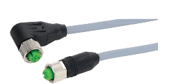
Can someone recommend a cable for a long run compatible with my setup? I am unsure how to tie the shield to panel ground. I have a plastic enclosure with 12mm male panel mount connectors. Do they make a cable that the shield ties to the metal connector. I guess I could then add a washer inside the panel underneath the mounting nut. Run a ground to that?

I have shielded cable but I think 18ga may be too big? Can someone give me the rundown on choosing the proper wire for PT100, would the overall length change anything?

This is what I have on hand- 18ga
https://catalog.belden.com/techdata/EN/8770_techdata.pdf


Thinking something like these? 22ga
https://cdn.automationdirect.com/static/specs/m12shieldcbl.pdf
 
Last edited:
Either 18 or 22 are OK. 22 makes more sense. I suggest you solder the RTD sensor wires to this wire to reduce resistance added.

Just tie the shield wire back to your ground bus in your control box.
Pete, I'm using M12 connectors at the end of my wires like shown. The pigtail end of these connect to RTD via screw terminals.

shield.png
 
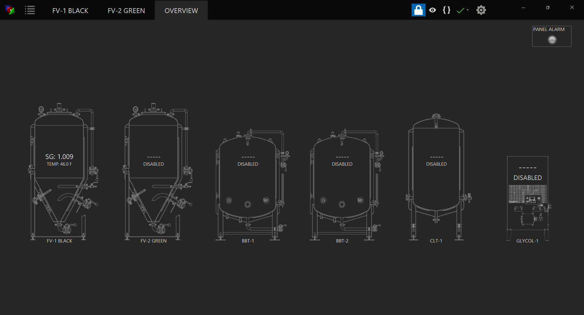
Thought I'd share the progress of my cold side panel. Supports step fermentation with automatic rest (whether d rest or dry hop) and cold crash. The workflow is as follows...

1. enable the fermenter
2. set auto or manual (manual allows for generic hysteresis)
3. set primary, rest and crash temps
4. set OG and estimated FG
a. rest SG is auto calculated
5. when SG is stable (utilizes a running derivative- "rest count") then a user defined rest timer starts
6. when rest timer meets rest duration, cold crash is activated

Each fermenter will have its own tab and running identical scripts. An overview tab is accessible which is essentially the main page to monitor everything at once.

I have a high/low alarm script that works along with my fermentation script. It will automatically shut off during ramp phases and turn back on during hold phases. The alarm script has a running derivative counter to assist with any potential spikes.

I'm currently working through the alarms shown (dry hop, spund, add finings). The idea here is that an email notification will be sent to my partner and I for the various actions across the multiple fermenters. I currently have OG as user input but thought about using TILT SG input at start of auto script to auto populate this field. Thoughts?

Ultimately the cold liquor tank and the two brite tanks will be controlled via 240V air conditioner in a cold storage room- this is the "sub panel" Ive been speaking of in previous posts. The fermenters will be controlled via glycol and solenoid vales.

This weekend will be the first wet test. All is working well when using a test script to change values. Should be 100% hands off if all goes well. Wish me luck!
BC-BLACK.png


BC-OVERVIEW.png
 
Last edited:
Pete, I'm using M12 connectors at the end of my wires like shown. The pigtail end of these connect to RTD via screw terminals.

View attachment 659944
I make my own ss three-wire probes using M8 shielded cable: htmsensors.com - C-MS3TZ-V075+C-FS3TZ-V075. They have three connections rather than 4) as described in a 10 year old thread on this site. Just search "make your own ss temperature probes." I seal the open end of the ss tube with silver solder.
 
A few RTD users have reported variation in their temp readings comparing probes against a certified/known good probe or each other. This should not be the case. RTD’s should deliver both high accuracy and repeatability - that’s the point of using them.

Here is a recommendation to identify the potential source of the discrepancy (amplifiers or the probes), assuming you have the RTD amp set up correctly (wiring, jumpers, pad resistor).

1. Apply a jumper across the amplifier wire-probe terminals and a known 100 ohm resistor across the probe-probe terminals. That will simulate a probe with no resistance in the wires and 100 ohms at the probe. A Pt100 probe should output 100 ohms at 0 deg Celsius, so with this resistor, you should get a reading of 0 in BC just from the RTD calibration alone.

2. Put a probe into a medium along with a certified/know-good temperature probe. Give them time to settle and note the temperature on the certified probe. Using an quality ohmmeter, measure the wire-probe resistance and the probe-probe resistance. Subtract the former from the latter to get the actual probe resistance. Check that resistance against a Pt100 resistance chart to see how close it is. The properties of these probes assuming they are of proper construction with platinum should yield an exact resistance which matches the chart. As above, if the medium is at exactly 0 degrees (quality ice water), the resistance should be 100 ohms.

Here is a link to a RTD chart:
https://www.sterlingsensors.co.uk/pt100-resistance-table

Here is a link to an online calculator as well: https://www.peaksensors.co.uk/resources/rtd-calculator-temperature-resistance/

Did a quick test with three probes I have. Here are the result, compared against two "unknown quality" thermometers (M1 and M2) and another RTD probe read via BruControl (M3). Probe 3 is M3 (measured via resistance vs. reported in BC). I suppose those invalidate the test since there is no known constant... but shedding some light nonetheless. All three probes read next to each other, but they read different than the other three, including M3.

upload_2020-1-2_20-24-34.png


FYI, R-R is the wire loop resistance, RTD should be the resulting sensor resistance. More testing to come!

Edit:I just measured the resistance of the probe reported as M3... net 109.4 like Probe 2. So it is reporting 1.3 degs higher via the amplifier... need to see if the amp is creating the discrepancy. Anyway, I am surprised there is this level of variance!

Edit 2: Just put a measured 100.1 ohm resistor across the amp and jumped the R:R (wire to wire) channel with same resistor lead... amp reporting -0.35 degs C in BC... that's pretty close to the expected 0.

Edit 3: BC is calculating correctly in the calibration.

Bottom line is RTD's, like all probes, need some refinement in order to measure accurately. I had always ASSumed they were plug & go with ultra-high accuracy. But the reality is they are VERY sensitive to resistance variations. Each ~0.4 ohm difference results in a degree C variation... which is more like 2 degs F variation. So connectors, wires, terminals, etc. should all be carefully managed to ensure no residual resistance gets added during construction.
 
Last edited:
Were these wired to the same amplifier or different amplifier channels? If so, what is the amplifier board being used? Mostly just for completeness, and to fully understand the test.
 
Were these wired to the same amplifier or different amplifier channels? If so, what is the amplifier board being used? Mostly just for completeness, and to fully understand the test.

Only M3 was measured using an amp - the others were measured via resistance and then the expected temps calculated. Sorry this isn't clear - I'm too lazy to document carefully!
 
Just one more question (I promise):

How are you measuring the resistance? When you get down to 0.1 ohms a regular 2 wire test might be misleading. Do you use a current source (1mA or something) to drive the force lines and then a voltmeter on the sense (like in a 4 wire bench DMM)?

Sorry to be a pest.
 
Kidding aside, I don't care if the reported value is 500℉ off of the actual temperature, as long as the offset is linear. I just replaced three CCS PT-100's (admittedly with a couple of connection points in the signal path) with Auber PT-100s with factory cable run directly to the RTD amp board. I had to add about -2.5℉ of calibration, but they are now rock solid and consistent across the entire brewing temperature band. I am having all of the happys. The numbers I see on my BC screen match what I read on my Fluke meter (+/- 0.5℉), and that's what I care about.

One more factor that may have influenced my initial bad experience: I removed the thermowells that my original PT-100s used. The Auber units are ½" NPT, so I've eliminated the lag inherent to a thermowell filled with SSR heat sink paste. I probably shouldn't have changed so many things at once, but IDGAF. It's working very well now.
 
Just one more question (I promise):

How are you measuring the resistance? When you get down to 0.1 ohms a regular 2 wire test might be misleading. Do you use a current source (1mA or something) to drive the force lines and then a voltmeter on the sense (like in a 4 wire bench DMM)?

Sorry to be a pest.
Hahaaaaaaa... I wish I was that good!! I just measured the R of the test lines and subtracted. Sorry to dash your hopes - this probably explains some of the variability above.

Actually... come to think of it, I DID NOT include the test lines... so I updated the calcs. Here is the new grid. Getting closer, but there is still a big discrepency between Probe 3 and Therm 3, which again use the same RTD (Calculated is based on its resistance and Therm 3 Measured is reported by BC via an amp).

upload_2020-1-2_22-48-51.png
 
I apologize- I meant to say I make my own 1-wire probes with M8 shielded cable as a suggestion for those that choose to use 1-wire temp probes.
I'm assuming that we are all discussing 3-wire PT-100's. Is anybody using a lab-grade 4-wire PT-100?
 
A beta tester reported same re: OTA. Said once flashed was OK again. My guess is the way the flash is partitioned from package to package. We'll test it. For now I'd recommend updating via serial/USB.

Edit: Suspense was killing me. Previous ESP32 with v45E on it successfully updated via OTA twice. So not sure if this is a 45C --> 45E hiccup only.
this was my experience also.. I will let you know if it happens on anything besides 45C-->45E Thanks for everything, will test some of the other new features this weekend...
 
I am still seeing intermittent spikes. I have a hunch this is either EMI, but through my house wiring or some voltage leak of sorts.

Earlier today, I got the circuitry fixed to my fermentation shed and have verified both the Air conditioner and BC panel are wired correctly and grounded, I used an outlet tester to make sure.

I have verified the spikes have nothing to do with the control circuit to the Air conditioner. I know this because I observe the spikes INTERMITTENTLY when I plug the Air conditioner straight to a receptacle bypassing the subpanel (or any control circuit associated with Bru Control panel). I started thinking, maybe this is an issue when high amps are drawn. I was correct, I also observe the spikes INTERMITTENTLY when my home Air conditioner kicks on or my electric stove, again these is a separate circuits from the Bru Control panel. I do not observe the spikes with lower amp draw devices.

I went around the outlets in my house (with an outlet tester) and noticed a few of them aren't grounded but Hot and Neutral are wired correctly, most of these aren't in use. Could this contribute to the problem? Please note, I am not using these outlets for AC and Bru Control panel.

I have also ensured the PT100 sensor and wiring is 20 feet away from these high amp draw devices.

Edit: I think i just figured out my issue, the PT100 sensor I have is about 40' long and un-shielded. I think this is acting as a giant antenna picking up any high voltage device in my house. When I use my other PT100 (same model) and a 10' cord, my issue goes away. That being said, would a shielded cable solve this issue or is it the length of the cord the issue. When I hook this up commercially, I see the Bru Control panel being at least 20'-30' away from PT100.
I also never completely eliminated these in my setup at the brewpub. Sometimes when my walk in cooler or furnace blower kicked on in the basement, I see spikes in the rtd values upstairs. I also found I could only ground the shields of my rtd cables at one end. When I had the shield connected at both the kettle and the panel I would get a lot of reading anomalies when the heating elements were switched on and off.
 
Which GPIO were you using (I'm guessing GPIO0)?

Try it with GPIO4 if you can.

I had the same problem and learned that it is something with (some) NodeMCU boards that pulling GPIO0 low causes it to reset. You can just pull that pin low with a lead and it will also reset.

Also, are you using an older firmware? If it is the GPIO0 thing it has been changed to the best of my knowledge to now allow you to do that.

I wasn't using GPIO0, I tried all the supported pins. I also had nothing connected to the board.

On the ESP8266 (and the ESP32 for that matter), there are certain pins that are pulled high at boot/output a pwm signal/or cause boot failure if pulled low. See https://randomnerdtutorials.com/esp8266-pinout-reference-gpios/
 
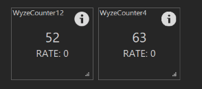
I just gave it a try on the Wyze plug (8266 based) board I have using GPIO12 and GPIO4, and it seemed to have worked ok. I tapped the pin with a grounded lead and it counted up without a problem. FW version 45A (I think)

Screen Shot 2020-01-03 at 8.27.44 PM.png
 
Last edited:
I just gave it a try on the Wyze plug (8266 based) board I have using GPIO12 and GPIO4, and it seemed to have worked ok. I tapped the pin with a grounded lead and it counted up without a problem. FW version 45A (I think)

View attachment 660153

Interesting, I am using the newest firmware 45E on a NodeMcu board. I will try an older firmware version.

Edit: I reverted the board to 45C and it works as intended. Must be a bug in the new firmware. Probably an updated library or something.
 
In trying to replicate your problem I tried flashing one of my NodeMCUs with 45E and I couldn't get it to work at all. I tried two different NodeMCU boards (same thing, just two copies) and I tried the 8285 and 8266 firmwares, both gave me the same error shown below.

I switched back to 45A and it seems to be fine with that.

ESP8266_45E.png
 
Back
Top