• Please visit and share your knowledge at our sister communities:
  • If you have not, please join our official Homebrewing Facebook Group!

    Homebrewing Facebook Group

BruControl: Brewery control & automation software

Homebrew Talk

Help Support Homebrew Talk:

This site may earn a commission from merchant affiliate links, including eBay, Amazon, and others.
I just spent the last few hours figuring out how to enable Amazon Alexa with BruControl via node-red.

So far I can turn on/off a global boolean and set a global value.

"Alexa turn on the boil kettle pump"

"Alexa set the fermentation temperature to 67"

I am 100% interested in this. It was the one think I had implemented on the BCS that I would really like.
 
Can i define various values and use them in an equation within if statement? I understand some of this may be redundant but it helps me see the equation quickly..

[Setup]
new value PV //FV-1 Input temperature
new value SV //FV-1 Hysteresis target
new value AH //Alarm Low
new value AL //Alarm High

PV = "FV-1 TEMP" Value
SV = "FV-1" Target
AH = 4
AL = 3

[Loop]
if PV >= SV + AH
"FV-1 ALARM" Active = True
endif

sleep 500
goto "Loop"
 
I don't believe this statement will work *if PV >= SV + AH* due to inline math not being supported. You would need to create an intermediate variable to hold the sum of SV and AH, then compare that variable to PV.
 
[Setup]
new value PV // Define new value Process Value
new value SV // Define new value Set Value
new value AH // Define new value Alarm High
new value AL // Define new value Alarm Low

PV = "FV-1 TEMP" Value // Defines PV as FV-1 Temp Input Device
SV = "FV-1" Target // Defines SV as FV-1 Target
AH = 3 // Defines default Alarm High threshold
AL = 3 // Defines default Alarm Low threshold

new value SV+AH // Defines new value combination Set Value + Alarm High
new value SV-AL // Defines new value combination Set Value - Alarm Low
SV+AH = "FV-1" Target + AH // Defines SVAH as FV-1 Target + AH
SV-AL = "FV-1" Target - AL // Defines SVAL as FV-1 Target - AL

[Loop]
if PV >= SV+AH // Deviation Alarm Active PV, ≥ (SV + AH)
"FV-1 ALARM" Active = True
endif
if PV < SV-AL // Deviation Alarm Active, PV < (SV - AL)
"FV-1 ALARM" Active = True
endif

if SV-AL <= PV // Deviation Alarm Inactive, (SV - AL) ≤PV
"FV-1 ALARM" Active = False
endif
if SV+AH > PV // Deviation Alarm Inactive, PV < (SV + AH)
"FV-1 ALARM" Active = False
endif
goto "Loop"
 
You cannot use math operators in variable names... how would the interpreter know the difference... for example: x = y+z? Did you mean that x should add y and z or use the variable named 'y+z'?

Also, if you define SV as being the value of '"FV-1" Target', and never modify SV, there is no real need to have is... just use '"FV-1" Target'.
 
Can I use this probe?

Semoic 3D Printer Parts HT-NTC100K Thermistor Temperature Sensor for High Temperature Filament 350 Degrees B3950 for 1M

It is 100K vs 10K

I have a 10g and 20g SS BrewTech MLTs and the thermoprobe will only take a sensor that is 3mm diameter.
 
You can, but the supporting circuit will need to have a pad resistor of 100k as well. I would also be concerned about noise pickup... it is a very high impedance.

If you are inclined, you can build your own probes. I used a quality Cantherm thermistor and put them into the Auber bodies. Takes some work to solder in, but my results were good. I did these when I originally had a BCS. Today, I'd probably go RTD.
 
If I can find a 3 mm probe that is ready I would likely prefer that. I am going to keep looking. RTD, Dallas, or 10K NTC will work. These are only to read the strike temp and Mash temp. I have been using a therapen but would be nice to log the mash.
 
You can, but the supporting circuit will need to have a pad resistor of 100k as well. I would also be concerned about noise pickup... it is a very high impedance.

If you are inclined, you can build your own probes. I used a quality Cantherm thermistor and put them into the Auber bodies. Takes some work to solder in, but my results were good. I did these when I originally had a BCS. Today, I'd probably go RTD.

These RTD's work pretty nice (waiting on ESP32 to accept RTDs, hint-hint) I like the quick disconnect feature, and you can customize on request, i had them make 200mm long probes... not sure if they can do a DS18B20 in there or not... https://www.ebay.com/itm/173841845218
s-l1600.jpg
 
These RTD's work pretty nice (waiting on ESP32 to accept RTDs, hint-hint) I like the quick disconnect feature, and you can customize on request, i had them make 200mm long probes... not sure if they can do a DS18B20 in there or not... https://www.ebay.com/itm/173841845218
s-l1600.jpg

Unfortunately I need just the probe without the triclamp. I actually have a few hanging around from my aurber pid days. I also need a 3mm diameter. These are 5 mm. SS Brewtech have small thermowells. I measured the probe that came with it, and it is 3 mm. I did find a 3mm probe RTD 3 wire on Amazon for $19. These are not heated so it is just to log my mash. I have 2 of their MLTs
 
Last edited:
I do not have Brucontrol, but I am very interested. Is there a way to build a "process view" where you can "see" the flow between different kettles? For example, have a layout view of your brewery and when, for example, the step for recirc through a RIMS tube, you see like flow arrows through that loop?
 
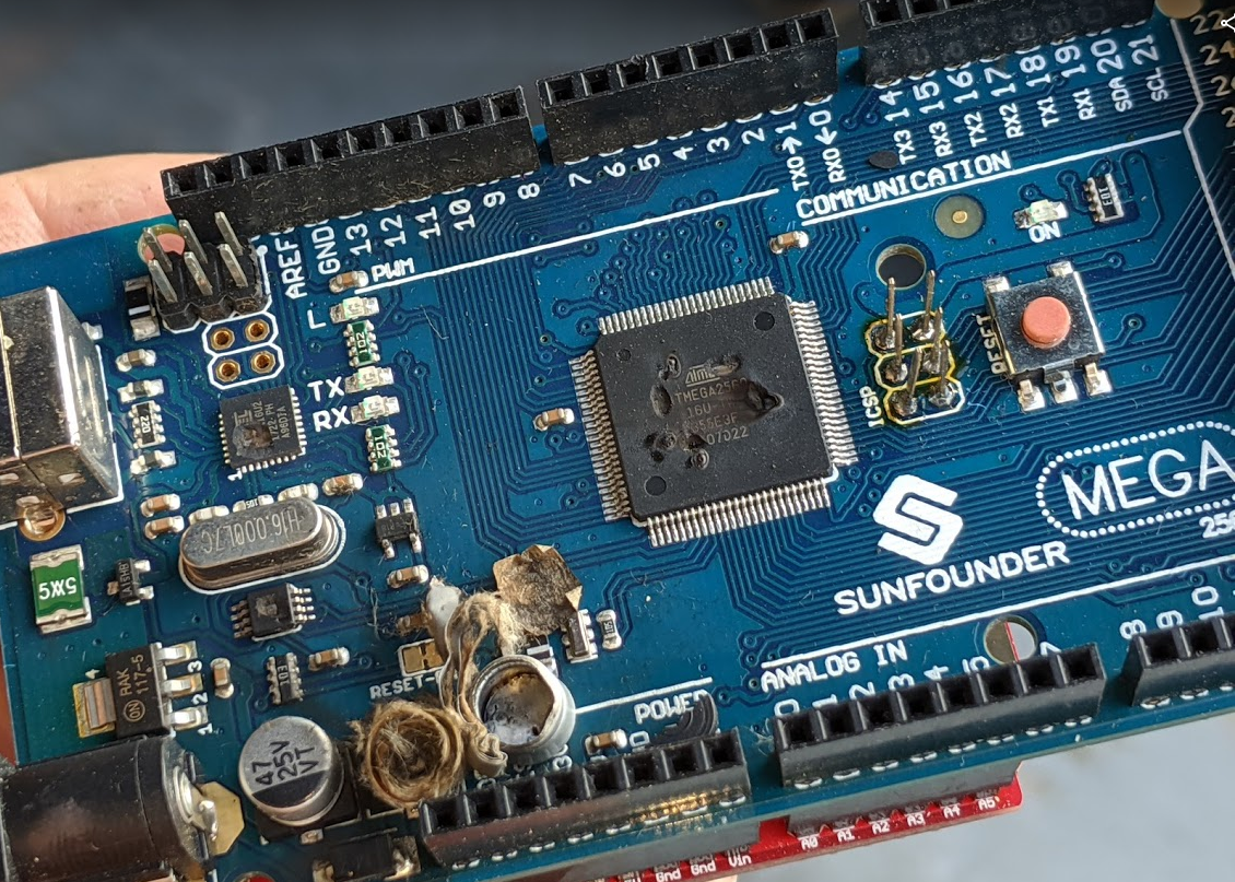
Fried a mega, was pulling out an unused contactor, and the base snagged the common wire of another contactor enough to tug it out and that common wire went straight into the power terminal and boom... I had the power off to the arduino, but this was a separate circuit breaker coming in for three phase to a 9kw element... the common wire was like a dart going for the double bullseye...
upload_2019-11-3_8-36-47.png

good news, I had a spare... bad news, It fried something on the screw shield, so ordered another one of those and will try to fix.. more good news, robotdyn boards are on sale for $33.66 today after a 10% amazon coupon, so will try one of those as a new spare, that price is awesome and de-soldering a jumper is less work than re-pinning a regular mega to get the w5500 board and screw shield to both work...
 
I do not have Brucontrol, but I am very interested. Is there a way to build a "process view" where you can "see" the flow between different kettles? For example, have a layout view of your brewery and when, for example, the step for recirc through a RIMS tube, you see like flow arrows through that loop?

I would say "no" right now... we have dynamic backgrounds for elements currently, so you could use that to change the image of an element, for an example, the RIMs tube. We are adding the ability to add graphics-only elements, which could for example show flow through them in a dynamic sense using animated gifs or image rotations..
 
Fried a mega, was pulling out an unused contactor, and the base snagged the common wire of another contactor enough to tug it out and that common wire went straight into the power terminal and boom... I had the power off to the arduino, but this was a separate circuit breaker coming in for three phase to a 9kw element... the common wire was like a dart going for the double bullseye...
View attachment 650972
good news, I had a spare... bad news, It fried something on the screw shield, so ordered another one of those and will try to fix.. more good news, robotdyn boards are on sale for $33.66 today after a 10% amazon coupon, so will try one of those as a new spare, that price is awesome and de-soldering a jumper is less work than re-pinning a regular mega to get the w5500 board and screw shield to both work...

Looks fine! Just dust it off and put it back in operation!
 
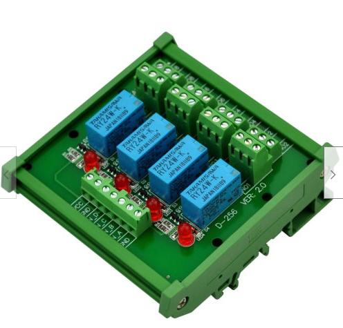
Wanting to implement 24v 3-wire valves, and it looks like this electronics-salon relay module would work the best.
upload_2019-11-3_14-51-54.png


I wanted a thin terminal block relay, but after searching for 4 hours, it looks like I would need both the SSR to 24VDC, then a 24VDC SPST to operate the valve correctly, they do not make a 'powered' version that works on a small 'trigger voltage'.

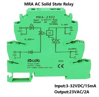
It looks like I would have to use this one to use the interface 3-5v signal to make 24V signal (I currently use this model for 24vdc coil contactors)
upload_2019-11-3_14-53-32.png

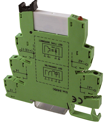
Then operate this SPDT one at 24V, using the NC and NO terminals for the close and open wires
upload_2019-11-3_14-54-44.png


Am I missing a better choice?
 

Attachments

  • upload_2019-11-3_14-48-42.png
    upload_2019-11-3_14-48-42.png
    697.7 KB
Oh... I mis-understood. Yeah I hadn't found any relays with solid-state front ends either. If you can use the second type of 3-wire relay, you only need the slim SSR.

Not meant as a plug, but this is why we made the Uni-Shield. A control panel using it requires no relays.
 
Sooo... Amazon sent me the PoE-Active version of the Mega Eth... I have the board working in BC with just removing the D7 solder jumper, wondering if anyone has the PoE part working... I have it connected to a known good Cisco switch, and 'debug ilpower event' shows nothing when plugged in, it acts like the board or Si3042 on it are disabled.. If I can get PoE working, this will make a great 8-channel remote RTD host...
 
Does BC support using a 1wire master chip such as ds2482? It's an i2c bridge for 1wire which takes care of all timing related ops. Also, when will web interface be released?
 
I ordered a 2nd RobotDyn Mega Eth and this one the PoE-ACTIVE works right out of the box, the lights come one when plugged in, I looked at a lot of docs, and the PoE board and chip is separated and logically independent from the Mega board, no jumpers or communications possible, it just uses 4 leads from the RJ45 jack and then gives power via Vin and Gnd... will troubleshoot the other one, and see how many RTD's this one can handle on a good PoE Switch...
 
Does BC support using a 1wire master chip such as ds2482? It's an i2c bridge for 1wire which takes care of all timing related ops. Also, when will web interface be released?

We have an I2C Element planned.

Web’s coming - don’t want to promise a time. Working out kinks in SQL back end database and some others... will publish that version, then get crackin on Web. I’d recommend screen sharing for now - even the one in chrome works pretty good.
 
Reading through some of the website info, and had a question about 8266 pwm. It mentions in the wiring maps that the frequency is ~500hz or ~1000hz, and I remembered that the esp8266 uses software pwm and the default is 1000 with range of 0-1023. Are you able to change the frequency and range in BC? If I am not mistaken Arduino uses has hardware pwm with range of 0-255 and changes the frequency depending on the hardware pin used.
 
We have an I2C Element planned.

Web’s coming - don’t want to promise a time. Working out kinks in SQL back end database and some others... will publish that version, then get crackin on Web. I’d recommend screen sharing for now - even the one in chrome works pretty good.

I ask for a lot, so this is just a suggestion, not a request. The ability to look at one workspace one one device and a 2nd workspace on another device at the same time would be really useful. A dedicated ferment workspace that is always on, and accessible via the network while the production workspace is used without disturbing it. An affordable way to have two workstations is really the only place that CBP3 beats out BC... even if that 2nd workstation is just read only
 
Reading through some of the website info, and had a question about 8266 pwm. It mentions in the wiring maps that the frequency is ~500hz or ~1000hz, and I remembered that the esp8266 uses software pwm and the default is 1000 with range of 0-1023. Are you able to change the frequency and range in BC? If I am not mistaken Arduino uses has hardware pwm with range of 0-255 and changes the frequency depending on the hardware pin used.

You are correct on the timers and frequencies. We don’t modify these as a matter of course. We’ve talked about making them all 1kHz but haven’t had a definite reason to do it.

If you are building from new, I’d skip the 8266 and go with the 32.
 
You are correct on the timers and frequencies. We don’t modify these as a matter of course. We’ve talked about making them all 1kHz but haven’t had a definite reason to do it.

If you are building from new, I’d skip the 8266 and go with the 32.

What about the range default on 8266? Does BC account for that with the pwm device? I've ran into issues on other projects where typical 0-255 is used and esp was not corrected so it was only able to output 0-25%.
 
I think the time has come to resolve the EMI feedback problem my customer has. Shielded temp probes provided a work-around but I think the feedback is messing with relays and such.

So just to confirm exact wiring of required diode. I'm going to go with a 1N4007 diode to implement a flyback diode. I'm not finding an exact wiring diagram that spells out what to do, so wanted to get some advice prior to wiring things in.

It's a 24V ball valve, but I don't have any other specifications as they were from China originally. I think I should be well covered by the 1N4007, and given these ball valves are controlling cooling fluid for fermentors, I'm not that bothered about speed of shut-off.

The diode needs to be wired between the power/ground wires right next to the automated ball valve. Correct? This should then suppress all that built-up potential from travelling up the circuits and screwing things up.
 
Are you getting noise at the start, during, or end of valve operation?

Motorized ball valves shouldn’t need much protection as the inductive load (motor) is pretty small. That said, if the noise is happening at the end of valve operation, the diode might help. Usually noise comes from big coils like solenoid valves.

The diode has a ring around it closer to one lead - tie that lead to the ground side of the valve, as close as possible.

Also I wouldn’t call shielding a work-around. It is a bonafide method to reduce noise. Look at coaxial cable - shielded for a reason - to isolate signals in and out.
 
The noise definitely occurs when the ball valve is being shut. It's a cheapy from China so who knows what's in there?

I guess what I meant by work-around is that it didn't solve the actual problem, just allowed my arduino's/RTD PT100s to keep working.

The interference may well be damaging other components for all I know. My client has reported some relay problems so I may have to power them independently rather than from arduino's.

Thanks for the help.
 
I think the time has come to resolve the EMI feedback problem my customer has. Shielded temp probes provided a work-around but I think the feedback is messing with relays and such.

So just to confirm exact wiring of required diode. I'm going to go with a 1N4007 diode to implement a flyback diode. I'm not finding an exact wiring diagram that spells out what to do, so wanted to get some advice prior to wiring things in.

It's a 24V ball valve, but I don't have any other specifications as they were from China originally. I think I should be well covered by the 1N4007, and given these ball valves are controlling cooling fluid for fermentors, I'm not that bothered about speed of shut-off.

The diode needs to be wired between the power/ground wires right next to the automated ball valve. Correct? This should then suppress all that built-up potential from travelling up the circuits and screwing things up.

If you go back to pg 37 post 1475 has a link to a paper with more than you ever wanted to know about EMI, it's a great read to learn the hows and why of EMI noise.
 
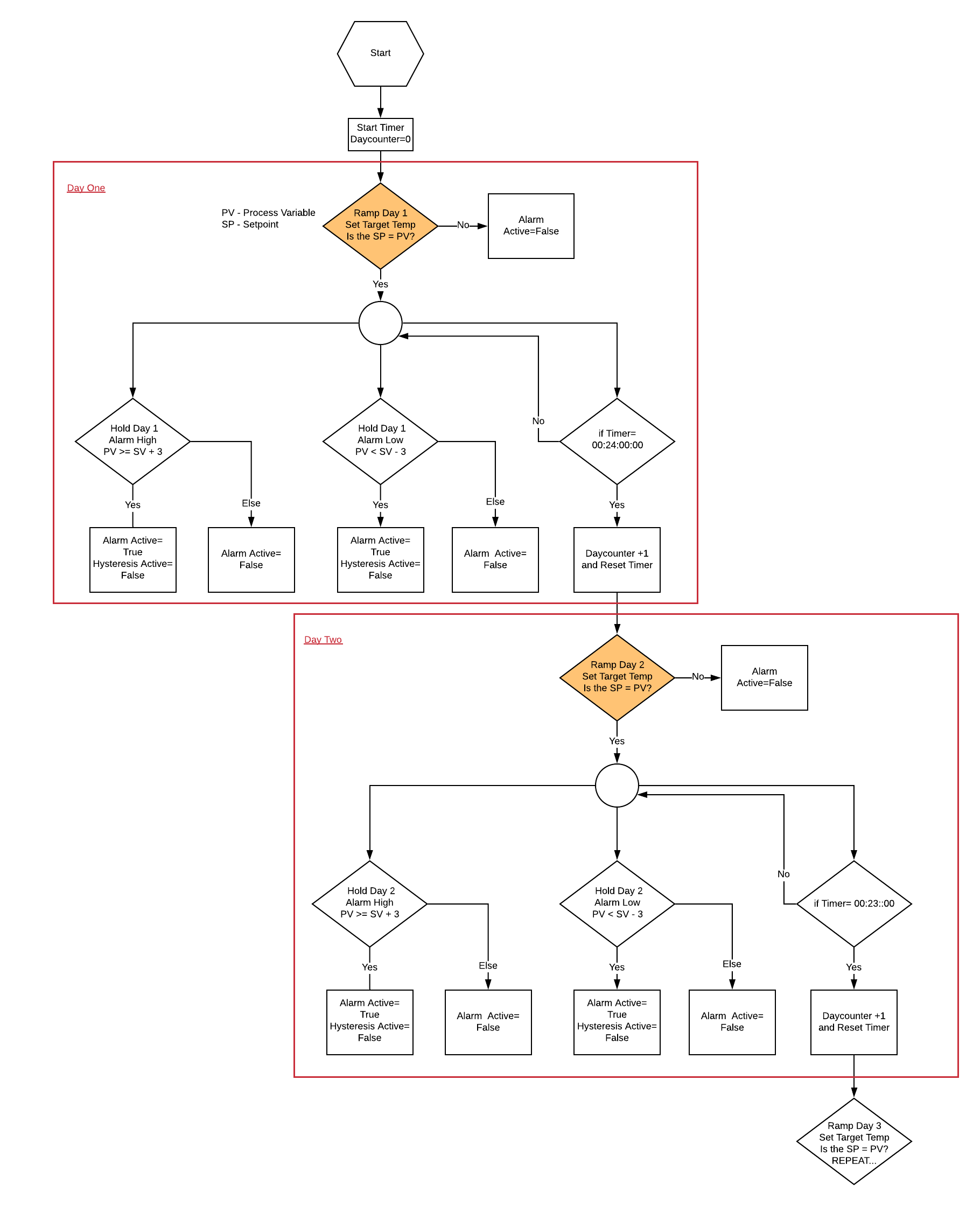
Ive made some progress with my fermentation script but am having issues with the ramp section "Ramp Day-1", shown in orange in attached.

I simply want to disable the alarm if the setpoint is not equal to the measured temp in both directions. Once the setpoint is equal to the measured temp the script should goto "Hold-Alarm". The alarm will be activated in this portion of the script if condition is met.

This is what i currently have for "Ramp Day-1" Everything is working up and downstream of this section

FV-1 TEMP = SPI Thermometer
FV-1 = Hysteresis


[Ramp-Day 1]
"FV-1 ALARM" Active = false

if "FV-1 TEMP" Value == "FV-1" Target
goto "Hold-Alarm"
endif

if "FV-1 TEMP" Value > "FV-1" Target
goto "Ramp-Day 1"
endif

if "FV-1 TEMP" Value < "FV-1" Target
goto "Ramp-Day 1"
else "FV-1 TEMP" Value = "FV-1" Target
goto "Hold-Alarm"
endif

Somewhere in the above script id like to add a +3 and/or -3 to allow for a deadband, not sure the best way to go about this. Pete, I tried to get the script you provided to work on various occasions, no luck.
Blank Diagram - Page 1(4).png
 
First you must consider that the likelihood of the actual and setpoint temps being the exact same is very low. Computers are very literal, so while you might consider 62 and 62.0148 to be the same, computers do not. Therefore, your first if block will rarely, possibly never, resolve to true.

Second, you cannot have any words after the else keyword.

This is what I figured with testing. I thought the decimal count (or precision) would account for this. Any ideas to get this to work? I was thinking with a defined range of a few degrees (so that 62 vs 62.0148) didn’t matter all so much.

I now understand where I went wrong with the else. I can’t setup a new condition which I have..
 
Back
Top