BruControl: Brewery control & automation software

Homebrew Talk - Beer, Wine, Mead, & Cider Brewing Discussion Forum

Help Support Homebrew Talk - Beer, Wine, Mead, & Cider Brewing Discussion Forum:

This site may earn a commission from merchant affiliate links, including eBay, Amazon, and others.
I've done a bunch of searching and can't find any conversations about BruControl supporting PT100 4-20mA transmitters.

These seem to be a better idea than doing long PT100 cable runs. Just need shielded 2-core cable (which is dead cheap compared to longer PT100s) instead of shielded PT100 sensor and cable.

I don't think the scripting would be up to converting values. Would that be something built into the firmware?

I don't think I have an immediate need for this (waiting on slow boat from Hong Kong with 4m PT100 probes), just a heads up.

https://www.instructables.com/id/Temperature-Measurement-With-RTD-PT100-4-20mA-Tran/

https://www.ebay.com.au/itm/PT100-3...m3f9b79042d:g:0esAAOSw9nJcYW5c&frcectupt=true

Thanks,
Angus.
For 4-20mA inputs you just need a 250 ohm resistor to create a 1-5V input to a mega. You use this as an analog input and setup appropriate calibration values.

That being said, adding more HW to a problem may not make the original issue go away.
 
That being said, adding more HW to a problem may not make the original issue go away.

Bang on Crane. I wasn't seeing this as a solution to my current hardware problems, but as a way to avoid long run shielded PT100 cables given the expense and delay of getting them in Aus. I can go to a bunch of shops near by and get shielded 2-core cable all day for cheap. I'm looking at over $AU100 for a 4 metre PT100 shielded probe made in Aus.

So I set up a (250ohm resistor + analog input) to BruControl and receive a value of 3.9V. I don't think the scripting is powerful enough to convert 3.9V into 72 degrees celsius based on available formulas and transmitter being 0-100C, etc, etc
 
Last edited:
Bang on Crane. I wasn't seeing this as a solution to my current hardware problems, but as a way to avoid long run shielded PT100 cables given the expense and delay of getting them in Aus. I can go to a bunch of shops near by and get shielded 2-core cable all day for cheap. I'm looking at over $AU100 for a 4 metre PT100 shielded probe made in Aus.

So I set up a (250ohm resistor + analog input) to BruControl and receive a value of 3.9V. I don't think the scripting is powerful enough to convert 3.9V into 72 degrees celsius based on available formulas and transmitter being 0-100C, etc, etc

I use a ton of 4-20 stuff on my system. It is an analog input using 1-5v. You then need to do the math of elements variables. It will need an offset and a multiplier. Offset because 0=1 and not 0, and the multi to associate steps to voltage. These will all be dependent on what your range is going to be. i.e. -50f/c to 1000f/c (whatever the range of the probe is). In my 4-20 stuff I can limit temp ranges to 0c-105c, so it tightens the range and improves the resolution considerably. No script work is needed because with your offset, and multi it is going to spit out the temperature, and you just have to set decimals points and a suffix if wanted.

If your example is correct..
offset = -25
multi = .12219

that should get you, your 72c or close too at least. ( assuming your on a mega and the 5v mega pin is at 5v)
 
Last edited:
oh yeh, I forgot about the adjustments and multipliers. I used those when creating the PT100 element.

Cool, that sounds like a much better solution than really long PT100's.

Thanks once again.
 
In the scripting language, is there a way to perform more than one operation on a line? I was trying to do some math and it wasn't working, but I realized that it was ignoring anything more than one operation per script line.

For example:
Code:
new value x
new value y
x = 2
y = 1 + x / 2
returns y = 3.

I'm just curious if I'm missing something.

Hi Nate,

No sorry, you cannot do inline math. This would be:

Code:
new value x
new value y
x = 2
x /= 2
y = 1 + x
 
I have a couple heating elements which are controlled by hysteresis and duty cycle elements. I was wondering if it was possible to have an LED display turn on when the element fires. At first glance, it doesn't appear I can do that.

So if I can't, I was thinking I could control the elements with digital outputs instead and script my own hysteresis and duty cycle "elements." If I did that, it would be easy to also turn on an LED when elements fire. Are there unintended consequences to scripting my own? Maybe if the Windows machine freezes or loses comm with the MEGA the element stays on? Am I making this up? Are there other reasons I might not want to do that?

Well, if you wanted an LED turn on when the element is on... you could tie the LED in to the element power directly. Obviously it would need to be able to accept whatever voltage that is. Alternatively, you could create a duplicate device to the one which controls the element, but have that device drive the LED. For example, if the element were driven by a PID Device Element on port 30, you could create a PID Device Element on port 31, using the same settings, including the input. Those two PIDs will turn on/off at the same time (well, technically off by maybe a millisecond or two).

Alternatively, you could write a script that turns on a Digital Output Device Element following another Device Element, but there will be a time delay between the communications, so this would work for fast changing stuff.
 
Was just fooling!

Anyhoo, verified @VacationLand 's findings - removing the solder jumper enabled the Ethernet power full-time. So there you have it! Good find here!

Also... @VacationLand ... that build is looking SWEET!!

I'm going to use a RobotDyn MEGA 2560 R3 with W5500 Ethernet for my setup. Is there any disadvantage to jumping PIN 7 to 3.3V vs removing the jumper on the back of the board to enable ethernet capability? Reason I ask is I'm not 100% sure of what I'm trying to remove (jumper). I see a solder point and D7 is identified on the back however, not sure if I need to break the solder connection or physically remove something?
I understand the ramifications of accidentally trying to use PIN 7 as an Digital Output, but I keep an inventory sheet of Pins/Ports so this wouldn't be a problem for me.
 
Last edited:
Oh... my bad! Yes, that's silly easy. On the output's Properties... Appearance... Value... Display Type... LED Indicator.

I guess I knew that... I like to see both versions at the same time... the text value (so I get the input/target or duty cycle) and the LED that gives me visual of when the element fires.

I don't think I can create a second hysteresis element on the same pin... Maybe I create a second one on an unused pin and set both up with the same parameters? A dummy hysteresis element?

Would that also work for duty cycle? Would they fire at the same time (or nearly at the same time)?
 
I'm not sure what I'm doing wrong, but I cannot get a duty cycle element to display correctly as an LED. In text mode it cycles on and off, while in LED mode it just stays grey, regardless of the colors I assign to ON and OFF. This is the case for both the real element and the dummy we were just discussing.

It does appear to work for hysteresis, though. Thoughts?
 
Yeah, sorry. It is not technically an ON/OFF device because the cycle length can be much shorter than the communications windows. In our brewing applications, a DC of 25% with a 2 second cycle length means it is on for only a half a second - which means it might not get caught.

No reason, just as long as your DC cycle length is long enough to catch it.
 
I've got some graphs which are tied to global variables.

The graph only charts values when global variables on the same workspace.

My global variables are getting fairly extensive now I'm tying in data from my website to the BruControl API.

Can we get the chart updating from global variables on different workspace?
 
I have used the new data exchange feature to enable communication between my website brewerschronicle.com and BruControl.

So my website you connect a fermentor to a ferment log. This fermentor has a bunch of "devices" attached (current temp, target temp, latest gravity, etc identified by the BruControl element id's). I have a piece of software that sits on the BruControl machine and matches BruControls element id's to the "devices" on my website. My software talks to my website API, and then sends info to the BruControl API (ferment name, estimated FG, latest gravity reading). It also grabs info from BruControl (latest temp at this stage) for the devices and submits it to my website.

Users of my site can create a ferment schedule based on days or gravity readings. Gravity readings submitted by Tilt, iSpindel, or manually cause the latest target temperature to be calculated and communicated down to BruControl automatically to set target values on the relevant hysteresis element.

Now that my blurb is completed, I can say the data exchange in the latest version is an awesome feature for 3rd party communication. It has really opened the doors to what I can achieve with the software. Nice work BrunDog.
:bravo:
 

Attachments

  • moreDetails.jpg
    moreDetails.jpg
    157.6 KB · Views: 65
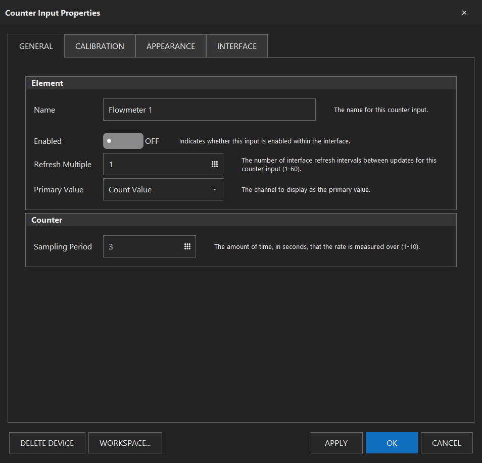
On a counter can someone explain what is the Rate Refresh used for. I understand the Sampling Period is a smoothing function. Just not sure why you would want to change the Refresh.
 
In the manual

SPI Sensor Considerations In firmware versions prior to 44N, RTD (via SPI) capable ports were actively pulled up to high voltage upon interface start-up. This ensured that RTD devices on the SPI bus did not communicate when they were intended. As a result, RTD ports were limited to a fixed number of certain ports. Starting in version 44N, the ports are not pulled up. This will allow for any digital I/O port to be used as an RTD port. Certain RTD amplifier boards contain built-in pull-up resistors which will ensure no communication until commanded. The system builder should make sure that any SPI sensor contains these pull-up resistors on board, otherwise add them (10 – 47k should be adequate).


Do the SPI boards you supplied have the resistor?
 
Yes, an Alias is a better name. It would be what is displayed in the Name field of an Element. You could write the element to display the Alias instead of the name if the Alias was not blank. It is possible to do the background trick with everything but a button. Buttons Elements are somewhat easier than a Switch Element on non touch screen as they have a bigger target area.

Not trying to put two digital Outs "Blue Pump" controlling the same Pump, just use a Switch, Button, or Global Element to control the "Blue Pump" digital Out on a different Workspace.

<SNIP>

I could certainly use an alias property. So the id of the element could be big and ugly for use in scripts or consuming through the API, but the user is presented with a nicely named console view.

I would alias both of the "FermentName" global variables with "Name" (and other fermentor not in the screenshot), but keep the element id at "BlackFridge_FermentName", "Ferm2_FermentName" and "Ferm3_FermentName" for use through scripts or the API.
 

Attachments

  • Capture.PNG
    Capture.PNG
    23.9 KB · Views: 32
In the manual

SPI Sensor Considerations In firmware versions prior to 44N, RTD (via SPI) capable ports were actively pulled up to high voltage upon interface start-up. This ensured that RTD devices on the SPI bus did not communicate when they were intended. As a result, RTD ports were limited to a fixed number of certain ports. Starting in version 44N, the ports are not pulled up. This will allow for any digital I/O port to be used as an RTD port. Certain RTD amplifier boards contain built-in pull-up resistors which will ensure no communication until commanded. The system builder should make sure that any SPI sensor contains these pull-up resistors on board, otherwise add them (10 – 47k should be adequate).


Do the SPI boards you supplied have the resistor?

No, but the RTD amplifiers do.
 
I could certainly use an alias property. So the id of the element could be big and ugly for use in scripts or consuming through the API, but the user is presented with a nicely named console view.

I would alias both of the "FermentName" global variables with "Name" (and other fermentor not in the screenshot), but keep the element id at "BlackFridge_FermentName", "Ferm2_FermentName" and "Ferm3_FermentName" for use through scripts or the API.
+1 it would be nice to shorten up the names on an individual workspace, but keep something longer and more intelligent for scripting.
 
I could certainly use an alias property. So the id of the element could be big and ugly for use in scripts or consuming through the API, but the user is presented with a nicely named console view.

I would alias both of the "FermentName" global variables with "Name" (and other fermentor not in the screenshot), but keep the element id at "BlackFridge_FermentName", "Ferm2_FermentName" and "Ferm3_FermentName" for use through scripts or the API.
I like to name my variables as what they are:


vVaValue like vVMashSetPoint.
Not a very nice name, but an Alias of "Mash Setpoint" would be great.

Also when duplicating a display only element on a Workspace (like a Digital Out on one Workspace and a Switch Element on a different Workspace, both with the alias of "Blue Pump".
 
my error:

Why would you change the Refresh Multiple for a Counter Element (or any other Elements that has this property)? This is how often the Element is polled(my assumption in conjunction with the refresh interval {on the Interface} ?

In other words, if your Refresh Interval is 1 second (the default), and you change the Refresh Multiple to 60, the Counter would be polled every minute (60 x 1 second)?

Is there any correlation with the Sampling Period, or are they totally independent of each other?
I do not understand the "practical" use of this Refresh Multiple property.

Is there a good reason to have a higher refresh for any Elements?
Is this to help with something like a Fementation Log where you might want less precise data ( like the fridge example in the manual)? It also seems the max would be every 10 minutes (Refresh Multiple x Refresh Interval 60 x 10 seconds)

Does anyone use this Refresh Multiple property on an Element?

I do see the "need" for slower communications with a wifi connection to set the Refresh Interval higher.
 
Last edited:
Counter as flow meters.

I have a hall effect flow meter that will put out a pulse for every revolution.

How do I use a Counter Element to figure the flow.

The choices of the Values for a Counter are

Count Value
Rate Value

I know that the Count Value can be turned into gallons using a formula based on counts per litre.

Mine says 400 counts per litre.

In my case the Formula would be

1 gal = 3.78541 x 400 Counts

Total Gals = Count Value/ 1514.164

So if I wanted 6.5 gallons, My Count Value would equal 9482. (small error as you cannot do half counts). Would be nicer if it read 6.5.

Would be nice to have a volume choice (litre or gals)

You would need to know the physical counts per litre for the meter. Since it resets when you disable the Counter, that would not be an issue.

What do you use the Rate Value for? Is that just not the speed of the flow and not a volume measure? I have never used a flow meter but have always wanted to measure my Strike and Sparge water into our MLTs.
 
I'm using these for keg volume monitoring. I don't use the counter directly, but have a global that is updated by a script to show the current volume and then hide the actual counter. I also have a "reset" button that resets the counter and the keg volume to 20L.

For the rate, I'm going to (don't have the bits yet) use that to monitor the flow rate of the whirlpool and the mash recirculation. I'm not sure where else I would use it.
 
Counter as flow meters.

I have a hall effect flow meter that will put out a pulse for every revolution.

How do I use a Counter Element to figure the flow.

The choices of the Values for a Counter are

Count Value
Rate Value

I know that the Count Value can be turned into gallons using a formula based on counts per litre.

Mine says 400 counts per litre.

In my case the Formula would be

1 gal = 3.78541 x 400 Counts

Total Gals = Count Value/ 1514.164

So if I wanted 6.5 gallons, My Count Value would equal 9482. (small error as you cannot do half counts). Would be nicer if it read 6.5.

Would be nice to have a volume choice (litre or gals)

You would need to know the physical counts per litre for the meter. Since it resets when you disable the Counter, that would not be an issue.

What do you use the Rate Value for? Is that just not the speed of the flow and not a volume measure? I have never used a flow meter but have always wanted to measure my Strike and Sparge water into our MLTs.


It does both count and rate, one is primary... (like using for a Tilt, there are 2 numbers displayed, one is displayed larger than the other.)

If you search this thread for *counter*, the 5th hit down looks like a good match, and the response to it is post 1183 https://www.homebrewtalk.com/forum/...tomation-software.624198/page-30#post-8406168
 
We do this as a labor of love, not for the $. Trust it is not an effort based on profit!

With respect to making money (the dreaded P word), I truly hope you do someday. As this project matures, it would be great if you charged more and were able to make a profit.

I prefer to pay for the products/solutions I use. For instance, there are plenty of free password management apps available, but I chose to use a paid app. Both because I want them to get paid for their work, but also so they stay in business and are there in the future for support and upgrades.

BruControl is a great platform that allows us home brewers to geek on our systems. We are mostly fiddlers anyway, right? It’s in our nature.

Thank you to the developers for your work! Brew on!
 
It does both count and rate, one is primary... (like using for a Tilt, there are 2 numbers displayed, one is displayed larger than the other.)

If you search this thread for *counter*, the 5th hit down looks like a good match, and the response to it is post 1183 https://www.homebrewtalk.com/forum/...tomation-software.624198/page-30#post-8406168
I sorta found that before. The one I purchased said 400 clicks per litre. Math was easy. In fact, while having some fields properties in the Counter Input Element so that it could have a Volume Value would be nice, I played with the new Global Element and did the math in a looping script. I will have to verify that the flow rate does not effect the clicks. The flow meter is on the output side of a SS Ball Valve that is either on or off. I have yet to wire and try it as I am still in the wiring process for all my new BruControl toys. I am really looking forward to doing my first brew with the setup. Just have to get it all wired and the two Arduino in their enclosure.
 
Which brings up another point. Can you Flash and Arduino over Ethernet or do you always have to use the USB. I find it cumbersome to hook up a USB in the Enclosure so I am just going to leave them connected to a USB powered hub that I can plug into when I need to Flash. One of the Mega(s) had a micro USB that fell off. Unfortunately, it was the one from BruControl and he nicely soldered the headers. I have ordered a Micro USB female and will try to replace it. One of the Pins broke on the OEM one so I cannot just re solder.
 
Back
Top