BruControl: Brewery control & automation software

Homebrew Talk - Beer, Wine, Mead, & Cider Brewing Discussion Forum

Help Support Homebrew Talk - Beer, Wine, Mead, & Cider Brewing Discussion Forum:

This site may earn a commission from merchant affiliate links, including eBay, Amazon, and others.
Hi @augiedoggy... timers can trigger alarms, not outputs. I suppose you could say timers trigger alarms which can trigger outputs, but in that case you are correct, it’s only in the activation direction. We did not plan on having timers trigger outputs on or off but this isn’t too difficult to implement. It wouldn’t be included for this release but I can queue it. The script to do this is really easy though - just a few lines.

Unfortunately you can not have multiple displays yet. It will be something we build in with web access. We did add the ability for different workspaces to be displayed via scripting, so you could have the workspaces alternate automatically or according to certain conditions. Sorry not ideal yet!
No problem, thanks for letting me know.
 
A somewhat random question: Can the Adafruit Grand Central be used with the Mega DIN Rail mount screw shields that you include in the BruControl Order list for the Mega?

Adafruit says it shares the shape and pinout of the Mega and that it's compatible with all of their shields, but I can't tell if it is compatible with the screw shields in the order list (which I've already purchased...) Can I use that screw shield, start with a Mega and then just switch it out for the Grand Central once I exceed the memory capabilities of the Mega?
 
Funny you mention.. just landed one of these bad boys.

Yes the pinouts should be comparable. Maybe not an exact copy, but the newer boards should have more functions per pin typically, so should be OK.

Technically, you won’t run out of memory - our firmware will. But that’s not imminent.
 
Here it is. Note: We haven't tested this yet, so it is not supported yet. We have tested (but not fully) the Metro M4, which is the smaller version of this processor / board. We know of one issue with the network setting storage, so will need to work that out.

IMG_6084.JPG
 
Funny you mention.. just landed one of these bad boys.

Yes the pinouts should be comparable. Maybe not an exact copy, but the newer boards should have more functions per pin typically, so should be OK.

Technically, you won’t run out of memory - our firmware will. But that’s not imminent.

Thanks! Good to know - I’m about to start building the new panel and wanted to make sure I have enough space for the inevitable future upgrades...
 
Is there a volt/amp meter that can display on the brucontrol software?
EDIT2--I am a dumdum. The wiring diagram was not clear to me and I switched the +/- for the 24VDC in. Switched those around and bingo-bango. Outputs ~4V at 240VAC in, and now works as expected with a 300/1024 linear multiplier. I rescind my rescission of my earlier recommendation. :p Sorry again.
EDIT--I cannot recommend these until I do some further testing/diagnosis to determine whether I have a faulty unit or if I wired something incorrectly. Sorry for posting before I completed testing.

FYI- Months ago I bought one of these CR Magnetics din-mounted voltage transducers from ebay. I finally got around to hooking it up and I can confirm that it works. The only weird thing is that the one I bought is supposed to have a range from 0-300VAC, but it outputs the max 5V signal at 240V. I don't think I'd pay $130+ for a voltage readout in BruControl, but it's maybe worth it for $50.
 
Last edited:
FYI- Months ago I bought one of these CR Magnetics din-mounted voltage transducers from ebay. I finally got around to hooking it up and I can confirm that it works. The only weird thing is that the one I bought is supposed to have a range from 0-300VAC, but it outputs the max 5V signal at 240V. I don't think I'd pay $130+ for a voltage readout in BruControl, but it's maybe worth it for $50.
easy to fix with 2 resistors set up as a voltage divider
 
I'll double check the signal voltage it's putting out, but it almost acts like it's a 0-250V version that got mislabeled as the 0-300V version or something. Making the linear multiplier 250/1024 results in a voltage reading that pretty closely corresponds with what my other voltmeters say.
 
I'll double check the signal voltage it's putting out, but it almost acts like it's a 0-250V version that got mislabeled as the 0-300V version or something. Making the linear multiplier 250/1024 results in a voltage reading that pretty closely corresponds with what my other voltmeters say.
EDIT--I am a dumdum. The wiring diagram was not clear to me and I switched the +/- for the 24VDC in. Switched those around and bingo-bango. Outputs ~4V at 240VAC in, and now works as expected with a 300/1024 linear multiplier.
I edited my original post to rescind my recommendation of this unit until I can do more testing. When I checked the output voltage, it was showing ~23VDC, which is obviously waaaaaay out of spec for something that is supposed to output a 0-5V signal. I hope I didn't damage the Mega.
 
Last edited:
Well the board I received seems to be DOA. A few others with a similar issue on the Adafruit forum. Prolly just gotta wait another couple of months for a replacement.
EDIT--I am a dumdum. The wiring diagram was not clear to me and I switched the +/- for the 24VDC in. Switched those around and bingo-bango. Outputs ~4V at 240VAC in, and now works as expected with a 300/1024 linear multiplier.
I edited my original post to rescind my recommendation of this unit until I can do more testing. When I checked the output voltage, it was showing ~23VDC, which is obviously waaaaaay out of spec for something that is supposed to output a 0-5V signal. I hope I didn't damage the Mega.

Nice!
 
Hello BrunDog,

Sorry to jump in the middle of this but I need a little help. I have been trying to switch over from serial to Ethernet , new board MEGA 256 ETH R3, and connected via usb serial bus, but cant get V43 interface firmware to download successfully (tried both

1. I get the error "receive message timeout, write error , failed to send, handle is invalid". I tried my laptop which is not connected to the main system with the running serial 256, and get the same error. I see the device as Com6 listed as "silicon labs CP210x USB to UART Bridge (COM6)". Board has power from USB and 5v PS. any thing I am missing that you can tell from this? I tried both 43.mega.E and 43.mega.s and both failed. Bad board or a jumper I missed?

thanks

Kdaz
 
Verify in device manager that that particular com port disappears when you disconnect the Mega and re-appears when you plug it in... Please provide link to exact actual board you bought. Should need just the usb, not 5v power also. What jumper are you talking about?
 
Thanks CWB,

Device manger sees the device and it doesn't when I unplug it. Board is

RobotDyn - Mega ETH - Mega 2560 Ethernet W5500 + Micro SD Card Reader/Writer with PoE, Compatible for Arduino Mega 2560 R3 Ethernet (No PoE)----- amazon link https://www.amazon.com/gp/product/B07L34ZG7J/ref=ppx_yo_dt_b_asin_title_o04_s00?ie=UTF8&psc=1

Reading everything I can find to figure this out, RobotDyn web page talks allot about jumping the pins for Ethernet etc.

green light steady, blue light flashing on the new board.

KDAZ
 
This isn’t a firmware or Ethernet issue - the firmware isn’t getting loaded. Looks like you have the USB driver but it might be a good idea to make sure you have the latest.

Otherwise I would try a combination of resets and attempts.
 
Driver says its the latest but there are some win 10 updates to do so i am downloading them now to be sure. Will try them a number of times once I am back up.

I've been out of the country for a few days and my new kegged Hefe is making me smile, so I will check and re- check everything tomorrow as at this point, I may be the problem.

Thanks for your help and I will report tomorrow on the status.

mañana
 
Thanks CWB,

Device manger sees the device and it doesn't when I unplug it. Board is

RobotDyn - Mega ETH - Mega 2560 Ethernet W5500 + Micro SD Card Reader/Writer with PoE, Compatible for Arduino Mega 2560 R3 Ethernet (No PoE)----- amazon link https://www.amazon.com/gp/product/B07L34ZG7J/ref=ppx_yo_dt_b_asin_title_o04_s00?ie=UTF8&psc=1

Reading everything I can find to figure this out, RobotDyn web page talks allot about jumping the pins for Ethernet etc.

green light steady, blue light flashing on the new board.

KDAZ

try searching this thread for robotdyn, it is mega 'compatible', not a mega 'clone'... there is a nice blurb from brundog about the board, tying pin 7 to 3.3v and those jumpers you mention... hint, post #1656
 
I am installing RTD for the first time, Mega w/W5500
I have the interface map, schematic, user manual, and this thread all up in tabs and have read each dozens of times..

I loaded the latest firmware v44J.ER (in K bundle) and could not figure out how to add the device (I am assuming use interface 14-17 since that is where the R is in the interface wiring map, and don;t see any reference to a 'virtual port' like there is with 1-wire)
I do not see 'RTD' or 'spi input sensor' listed when I select 14-17
I do not see a new range of virtual ports become available

I loaded v43.FR firmware and see the same thing...
I was on RC build 11, so updated to build 14 and see same thing..

Questions
1 - Are 14-17 what I should be selecting when I click 'Add Device'?
2 - Does the Arduino need to be actively talking to the RTD amplifier board(I think it is, just asking hypothetically) during boot or something for the drop-down to show up?
3 - How the heck to I add the RTD device type?
 
OK, thank you... I got it... but I almost didn't... I was going to reply back... "But I am using v44J.ER..."

IMHO, where it says "Note: SPI Sensor Inputs are available only when the associated Interface’s Settings have the correct Wiring Map selected (e.g. “With RTD)." on page 35 in the manual, it looked to me like it is just asking you to make sure you programmed v44J.ER and not v44J.E, maybe a reference to "Settings --> Interfaces --> Edit --> Wiring Map" or something... but hey, I may not have even caught that... thanks again
 
Happy with RTD, did some calibrations with ice water and microwaved water in a well insulated cup.. ice water was within a half a degree, but the high temp test shows a pretty big gap at the temps I want to use it for, the RTD matches the glass thermometer, but the 1-wire is 4-5 degrees low... now have to figure if one or all of my 1-wires is off that much... they all seemed close last time I checked......
IMG_20190413_121731.jpg IMG_20190413_121834.jpg
 
Good to know. I don't think anyone has done a direct comparison before - thank you. Would be curious to see more comparison data against a certified thermometer. I'm surprised because 1-wire should be is typically with a degree or two of accurate. Not as accurate as RTD, but that's what you get for cheap and easy to wire I guess!
 
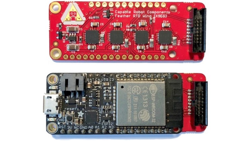
That's really sweet! Nice find! Alas, this wouldn't be compatible out of the box... it connects via USB serial communications with the Feather, not SPI. We could probably update the FW to accommodate that, though their library is python, which is interpreted and horribly slow compared to compiled native machine code.

I am sure Adafruit will carry these when they become available.
 
Lol. Sometimes the board doesn’t get properly put in programming mode and rejects the upload. I honestly don’t know how to fix it!


BrunDog, CWB, please accept my apologies. I could blame the beer, but I did this for two days before trying again last night.
I was the problem. updated drivers and re-testing made no difference until I read the directions (again) and typed "5" in-place of "COM5" on the mega firmware install menu. Works quite well when you do it the right way.

Mea Culpa........

Post 1656 looks to have all the info I need to complete the install, and will remove the pin 7 jumper next.

Thanks for your time.
KDAZ
 
I thought I saw the information somewhere regarding the ADC resolution for the ESP32 in Brucontrol, but I can't seem to find it. I know the chip supports 12 bit resolution, but does anyone know if it is set to 10 bit or 12 bit in BC?
 
That's really sweet! Nice find! Alas, this wouldn't be compatible out of the box... it connects via USB serial communications with the Feather, not SPI. We could probably update the FW to accommodate that, though their library is python, which is interpreted and horribly slow compared to compiled native machine code.

I am sure Adafruit will carry these when they become available.

I am looking at the schematic, it looks like it gets power from USB, but uses the SDI,SDO, SCLK, and CS for communications, it is just 4 MAX31865's after all.. https://github.com/CapableRobot/SenseTemp/blob/master/revisions/CREAES/SenseTemp - CREAES - Schematic.pdf


edit - biggest issue looks like it would be changing it from 4-wire to 3-wire so you can use the easy to obtain standard probes would be very, very intricate... I sent them a note requesting the next PCB to have the trace moved so that one could 'cut and solder' jump Force2 from GND to Force+
 
Last edited:
This is exactly what I do with my boil kettle, Its the only time I need to unlock the setting on the software while brewing to go in and enable the duty cycle mode after I bring my kettle up to 190 degrees with the pid function and add the antifoaming agent.

Unrelated question... I see in the new timers feature theres an ability to activate outputs but is there a was to deactivate outputs or any plans to implement that feature? say if I want my boil kettle to automatically turn off after a 75 minute boil?
I know I can write scripts for this but looking for simplicity right now.

also just in case its there and I havent figured it out.. In the new software, is there a way to display multiple workspaces at one time on 2 screens.. We have a 50" display I keep on above our brewing system with all our fermenter temps and /tilt info like graphs and I was wondering if there was a way to keep that up there while using the hot side brew controls on my touchscreen. I know it was asked about a while back but dont remember the outcome of the conversation.

I also have a big screen above my Brewery. In fact, I have two. How about eRest? Right now I plan to add an HDMI splitter to my computer and run one to one of the Big Screens. But that will just duplicate what I have. A second screen would be great as with my old BCS i had a huge Timer and Temp for my Mash. I could easily duplicate that on a different Workspace. I would also like to be able to display two Workspaces, on separate video platforms.
 
On a different note: Replacing an Arduino. Once you create a Workspace with some Device Elements, you cannot move to a different interface as far as I can see. For those that have the Robodyn Mega, the USB connector is COCO, so be careful. Mine came off and one of the pins Broke off. I am going to replace, but I would leave the USB Cable plugged in once and done. I was removing the cable and the connector broke. So if I cannot fix it, i will be getting another. I assume that when you replace an Interface:
1. Same Interface Name
2. Same Wiring Map Firmware
3. Same Type of Device : Mega with Ethernet 5500 Shield.
4. Same Type of Connection (Network TCP).

Are these solid? Other considerations?


All you have to do is update the new mega with FW, and then change the ip in brucontrol. ( or keep it the same and flush your mac table)
 
I did that after touching a 5v 1-wire connection to the chassis by accident, thought I fried the arduino, it was dead. I changed the static dhcp entry in my router... and then fiddled with the dead one and a firmware flash un-bricked it... but changing the IP in BC is the easiest way, somehow I did not think about that at the time..
 
Yes. If replacing a serial interface, just change the COM port in BC to reflect the new one. Likewise, if replacing a networked interface, either set the IP to be the same (reboot the PC to clear the table per DB’s comment above), or change the IP address on the interface and update that interface in BC to the new address.
 
I am looking at the schematic, it looks like it gets power from USB, but uses the SDI,SDO, SCLK, and CS for communications, it is just 4 MAX31865's after all.. https://github.com/CapableRobot/SenseTemp/blob/master/revisions/CREAES/SenseTemp - CREAES - Schematic.pdf


edit - biggest issue looks like it would be changing it from 4-wire to 3-wire so you can use the easy to obtain standard probes would be very, very intricate... I sent them a note requesting the next PCB to have the trace moved so that one could 'cut and solder' jump Force2 from GND to Force+

Yes, you are correct. Good find. We would need to update the wiring map in FW to make sure the SPI pins line up, but that’s easy enough.

The 4 wire RTD requirement is definitely a miss. I suppose you could splice in your own 4 conductor wire right up to the sensor to make a 4-wire. That would work but would make waterproofing a bit harder.
 

Latest posts

Back
Top