BruControl: Brewery control & automation software

Homebrew Talk - Beer, Wine, Mead, & Cider Brewing Discussion Forum

Help Support Homebrew Talk - Beer, Wine, Mead, & Cider Brewing Discussion Forum:

This site may earn a commission from merchant affiliate links, including eBay, Amazon, and others.
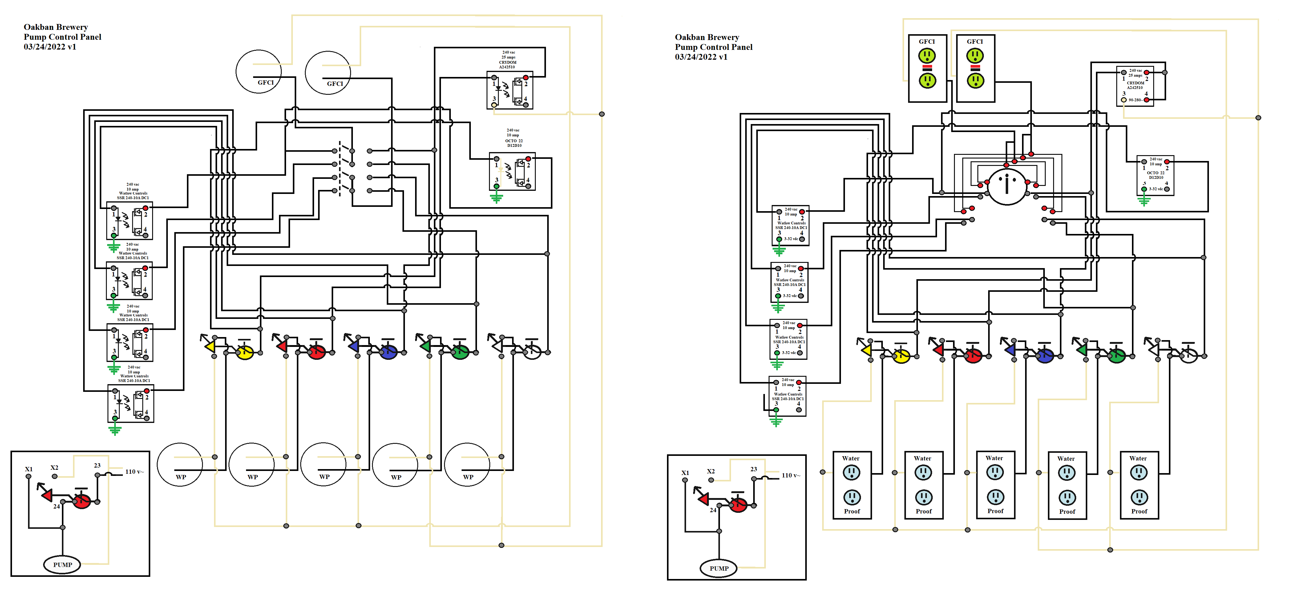
Schematic for my panel:
pump Box1.png


Side by side with Pictogram: I prefer the Pictogram as easier for me to visualize the wiring. The main differences are the Rotary switch and the Outlets. The Pictogram SSR could be correct on a Schematic from what I see on the web. But I guess the Schematic is the "right" way to display it.

pump Box3.png
 
I have three Crydom MCPC2450D Proportional Controllers that are 40-20ma type.

Any help on wiring would be appreciated.

This is the data sheet:
https://assets.alliedelec.com/v1575457953/Datasheets/48c0004eab09dfc0198ce5552c53fe3a.pdf
This is a previous post I made with a Diagram of my plan.
I have both the Crydom MCPC2450D Proportional Controllers and the 10PCV2425 Proportional Controllers. The 10PCV2425 Proportional Controllers are 0-10 v type but are rated at 25 amps.

I will be using a 5500 w Element?

If the Crydom MCPC2450D Proportional Controllers will work, I will use two of them on my HLT.

I would then use the 10PCV2425 Proportional Controllers for different Elements in the Quadzilla.

If they are not good, I will sell on EBAY.


I just found five Crydom 10PCV2450 Proportional Controllers (2-10 v Input) that I have. I will get an
Analog Amplifier – BruControl
if I do not have one. I think that is the best solution. I only need 4 so I have a spare and the AA-3 can handle all 4!
 
I am getting deep into wiring up my panel and want to double check a few things with the experts. I am using a Unishield with Grand Central (3.3V).
1) SM6004 flow and temp meter. Outputs 4-20ma signal. Flow range is 0-6.6gpm. Temp range is -20-80C. If you exceed the max, it will send >20mA. I have a Chugger pump that will exceed flowrate if head <6ft. The temp will exceed if used on BK. I am planning to use a ~132ohm resistor on temperature and 150ohm on flow. Does this seem reasonable?
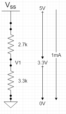
2) I have a cheap flowmeter from Adafruit that has pulsed output 0-5V. I think I need a voltage divider like below. Does this look right?
1648594139046.png

3) Would I also use a similar voltage divider for an analog sensor that outputs 0-5V (like the Brucontrol volume sensor)?
3) SSR outputs will use the P (pin) output, not the D (driver). Input range is 3-32V
4) For sensors or devices that need power and have large input range like 5-24V, is there a preference? I have both 5V and 24V power supplies.
 
I would think that you would user the D pins for any regular SSRs. For Proportional Controller Type , use the P pin to something like an AA-2 then the Proportional Controller.
 
I am getting deep into wiring up my panel and want to double check a few things with the experts. I am using a Unishield with Grand Central (3.3V).
1) SM6004 flow and temp meter. Outputs 4-20ma signal. Flow range is 0-6.6gpm. Temp range is -20-80C. If you exceed the max, it will send >20mA. I have a Chugger pump that will exceed flowrate if head <6ft. The temp will exceed if used on BK. I am planning to use a ~132ohm resistor on temperature and 150ohm on flow. Does this seem reasonable?
2) I have a cheap flowmeter from Adafruit that has pulsed output 0-5V. I think I need a voltage divider like below. Does this look right?
View attachment 764416
3) Would I also use a similar voltage divider for an analog sensor that outputs 0-5V (like the Brucontrol volume sensor)?
3) SSR outputs will use the P (pin) output, not the D (driver). Input range is 3-32V
4) For sensors or devices that need power and have large input range like 5-24V, is there a preference? I have both 5V and 24V power supplies.

EDIT: Use 1k and 2k in place below.... sorry about the bad math!! See post 7071 below.

1. Not sure your question - are these the resistors you want to use to convert 4-20mA to 0-3.3V? You cannot exceed 3.3V input, else you may damage the microcontroller.
2. Using a 2.7k and a 3.3k per below will give you the division you want.
1648682342253.png

3. Yes
4. No, use D pins. There is no reason not to - you want to minimize current draw on the microcontroller chip.
5. No matter. Just think about what else is shared on those power supplies. You might try to consider 5V "clean" and 24V "dirty".
 
Last edited:
Along the same lines:

I am ready to start wiring my SSR panel and some of the BruControl components.

I do not like any "hot" leg to a 220 circuit so I have Contactors and Standard SSRs to control one leg of each 220 v Heating Element (Double Safety, I know, but I had the SSRs laying around). The other Leg will be controlled with an AA-2 set for 0-10v . These will control Crydom 10PVC2450 Proportional controllers. Also the single SSR becomes a Safety when I use only one Big Mac Element.

I have one 110v (Radiator Element).

My Quadzilla will be on one 30 Amp Circuit (all 4). I am going to use it to heat water and also control my modified Herms water bath (Chillzilla with Hot Water Outer Tube and Wort Inner Tube).

The Big Mac is my 50 gal HLT. It has two 5500 x 240v Elements. I will use both to heat the Water but switch to one via scripting when withing 5 degrees of target. (the one Hot Leg will be off via its SSR.

I have a single SSR to control BOTH Big Mac contactors.

I also have some 30 Amp cutoff switches so I can manually kill the power.

I have some 22/6 unshielded cable which is fine for Standard SSRs. Should I use shielded twisted pairs (signal and ground) from the AA-2 to the 10PVC2450 controllers?


Any comments would be appreciated before I commit to soldering!

aa2 plan.png
 
Last edited:
I think this is much more complicated than needs to be. This *might* be double safety, or it might be quadruple the failure risk. You should always target the minimal number of [correctly sized] components to get the job done. Use the extra space to give room for expansion in the future.

I didn't review this thoroughly, but you should not wire one line of a heating element through one binary SSR and another leg through a proportional SSR. Remove the binary one and let the proportional one do the work. Plus SSRs leak voltage - so there isn't really any safety added. Your contactor serves that role.
 
1. Not sure your question - are these the resistors you want to use to convert 4-20mA to 0-3.3V? You cannot exceed 3.3V input, else you may damage the microcontroller.
Yes, these are resistors to convert 4-20mA signals. I am pretty sure they are correct, just doing a sanity check.
 
OK, I see the point as slightly more complicated. I will add another control SSR for the Big Mac 2 Contactor.


As far as future, I have the power, space and Proportional Controllers to divide the Quadzilla into 3 legs.

Quadzilla 1 would be two Heating Elements and Quadzilla 2 and Quadzilla 3 would be singe Heating Elements of the Quadzilla.

What are peoples thoughts on this? While I am only heating water now, I might be convinced to go to a RIMs system instead of my modified HERMs using the Quadzilla as designed.

The only downside I see is that I need a second AA-2.

Also do I need shielded twisted pairs from the AA-2 to the Crydom 10PVC2450 or is non shielded fine?
I have twisted shielded pair (that I will use for Temp Probes) and 22/6 awg wire. If it does not matter, the 22/6 conductor means less wires between the AA-2 and my SSR Panel.

Why not use a DC coil contactor and drive it directly off the UniShield?

Also, I’d just wire all elements of the QZ together. There is no advantage of powering individual elements. We did say this is an option initially, but don’t see any advantage of increasing heat density on one element while leaving the others off.If you use a proportional SSR, you’ll have perfect control.
 
I have the 24 vac contactors. I asi have several SSRiI am going to separate the 2 Big Mac Elements to their own contactor. I will keep all the Quadzilla Elements as one. Plan is coming together. What about type of wiring from the Aa-2 to the proportional controller (crydom 10PVC2450). I would prefer to use 22/6 unshieled wire but I do have twisted pair wire as well
 
Select the right wire for the right use. 22 AWG can carry ~5A, so is much bigger than needed for the SSR input in terms of ampacity as thats probably ~15mA, but sometimes really small wire is hard to work with - so 22 is good.
 
Why not use a DC coil contactor and drive it directly off the UniShield?

Also, I’d just wire all elements of the QZ together. There is no advantage of powering individual elements. We did say this is an option initially, but don’t see any advantage of increasing heat density on one element while leaving the others off.If you use a proportional SSR, you’ll have perfect control.
something like this?
https://www.amazon.com/TWTADE-JQX-6...=12+vdc+coil+voltage+cont,aps,194&sr=8-4&th=1
or even less:
https://www.amazon.com/dp/B07C78SLK...pY2tSZWRpcmVjdCZkb05vdExvZ0NsaWNrPXRydWU&th=1
 
I saw that the second cheap one is only 10 amps so no good. The other is 80 amps so I am ordering them. I will be selling the 24 vac ones one E Bay along with the SSRs.
 
I remember at one time someone was asking about the capability to run two electric elements at the same time and have them "combined" per se in Brucontrol so that the total power of both running at the same time would never go over a certain level. So say I have 2 120V elements and I do not want them to ever go over a total of 80% total power combined and if I change one element to say 60% brucontrol would auto modify the other element to 20% real time.

Was something like this ever implemented? It was probably several years ago when someone was talking about it. I was just curious as I am looking at implementing that scenario now with a 120V element in hot tank after transferring from the boil kettle to keep it hot and then another 120V in a RIMS with constant circulation during the mash. Only have 15 amp plug being used. :)

I did take a quick look at the latest manual and tried some searches in this thread and did not see anything.
 
Last edited:
I remember at one time someone was asking about the capability to run two electric elements at the same time and have them "combined" per se in Brucontrol so that the total power of both running at the same time would never go over a certain level. So say I have 2 120V elements and I do not want them to ever go over a total of 80% total power combined and if I change one element to say 60% brucontrol would auto modify the other element to 20% real time.

Was something like this ever implemented? It was probably several years ago when someone was talking about it. I was just curious as I am looking at implementing that scenario now with a 120V element in hot tank after transferring from the boil kettle to keep it hot and then another 120V in a RIMS with constant circulation during the mash. Only have 15 amp plug being used. :)

I did take a quick look at the latest manual and tried some searches in this thread and did not see anything.
There is a "dutycycle" and "interval" commands where you can control a duty cycle element with scripting.
The issue is that you would likely want to use PID or Hysteresis for the RIMS which is automatic. So how to you translate what the PID or Hysteresis is in "Power" is the question. I am not sure you can (or want to on a 15 amp circuit.


You could limit the power via the elements themselves:

Get these elements:
https://www.amazon.com/Eastman-6005...r+heater+element+240+1500+watts,aps,94&sr=8-5
Using only 120vac this is a 750 watt element.
or this one:
DERNORD Cartridge Heater 120V 750W Hot Rod Heating Element Replacement 1/2 Inch Thread - - Amazon.com

the two at 100% would be 1500 watts.

With 120v, that is 12.5 watts. That is slightly over the continuous use of 80%, but I think that a brewing session where the mash is RIMs for less that 2 hours (we mash for 90 minutes max), you could use the whole 15 amps as it is not continuous use (over 3 hours).

In addition, the PID or Hysteresis "power" is not 100% keeping something heated that is already at temperature. The issue becomes is 750 watts enough?
 
@BrunDog quick question, is there a firmware available for this esp32 board (w32-eth01) with integrated ethernet? I have a pile of these and they would be useful for controling certain items in my system. I was going to leverage a POE adapter to power and provide connectivity.

https://www.amazon.com/JacobsParts-WT32-ETH01-Ethernet-Bluetooth-Development/dp/B08WC15NWZ

Would have to see if the LAN8720A chip can use the existing code. The current code is expecting a W5x00 chip.

Will take a look and LYK.
 
Since I decided to go with DC Contactors I have lots of room in my SSR box that has my PID and Hysteresis Proportional Controllers along with two standard SSRs for my ignitors.

I am not worried about my Standard SSR for the ignitors as they are only on for 7 seconds rarely (normally once per brew session)

I could have my DC Contactors in that same box along with my AC to DC transformers.

Is EMI an issue with putting:

1. The DC Contactors and the Proportional Controllers in the same box?

2. The AC to DC transformers and the Proportional Controllers in the same box?
 
There is a "dutycycle" and "interval" commands where you can control a duty cycle element with scripting.
The issue is that you would likely want to use PID or Hysteresis for the RIMS which is automatic. So how to you translate what the PID or Hysteresis is in "Power" is the question. I am not sure you can (or want to on a 15 amp circuit.


You could limit the power via the elements themselves:

Get these elements:
https://www.amazon.com/Eastman-6005...r+heater+element+240+1500+watts,aps,94&sr=8-5
Using only 120vac this is a 750 watt element.
or this one:
DERNORD Cartridge Heater 120V 750W Hot Rod Heating Element Replacement 1/2 Inch Thread - - Amazon.com

the two at 100% would be 1500 watts.

With 120v, that is 12.5 watts. That is slightly over the continuous use of 80%, but I think that a brewing session where the mash is RIMs for less that 2 hours (we mash for 90 minutes max), you could use the whole 15 amps as it is not continuous use (over 3 hours).

In addition, the PID or Hysteresis "power" is not 100% keeping something heated that is already at temperature. The issue becomes is 750 watts enough?

Thanks for the response, I already have the heating elements for both RIMS and what will soon be in the HLT and they are the same element with each being 1400W at 120V. I can already set manually (or scripted for that matter) the % power it uses for RIMS, just dont remember what the field is and it does reduce the total power it uses. If ramping up or if my temp is low I leave it at 100%, but once temp is good I generally lower it to like 40 or 50% and obtain a smoother heating cycle that way.

This is what I meant by ensuring the total combination of both do not go over say 80% or 90% and when one gets updated it auto changes the other to go lower if needed.

I am working and cannot bring up my BruControl to see what field I am updating. I have checked my overall power meter for the system and when I adjust that field it definitely reduces the power being used.

If nothing is built into BruControl, then I will have to come up with a scripted method.
 
Last edited:
Hello. The hard drive on my computer recently died and I replaced it with a fresh win10 install (older computer). I managed to already back-up my BruControl settings and data. That was a huge relief. However, I was using Node-red to import recipe data from Brewfather and send data back to Brewfather at the end of a session. I would love to avoid rebuilding my flow from scratch so I was hoping that someone would be willing to share their node-red flow with me, even if it uses Beerxml to start with.

Thanks for considering.
 
Edited...

Oh, wait yes these values divide up to 6k ohms, not 5k ohms... BIG OOPS (at least damage wouldn't occur).

Use a 1.7k (not 2.7k) and you get the correct result. Unfortunately, 1.7k is not a common value, so you can use a 1k and a 2k respectively, which will yield 3.33V at 5V input. If you only have 1k resistors, you can use 1 at the top of the divider, and 2 in series at the bottom of the divider. 1/4 watt is all you need.
 
Last edited:
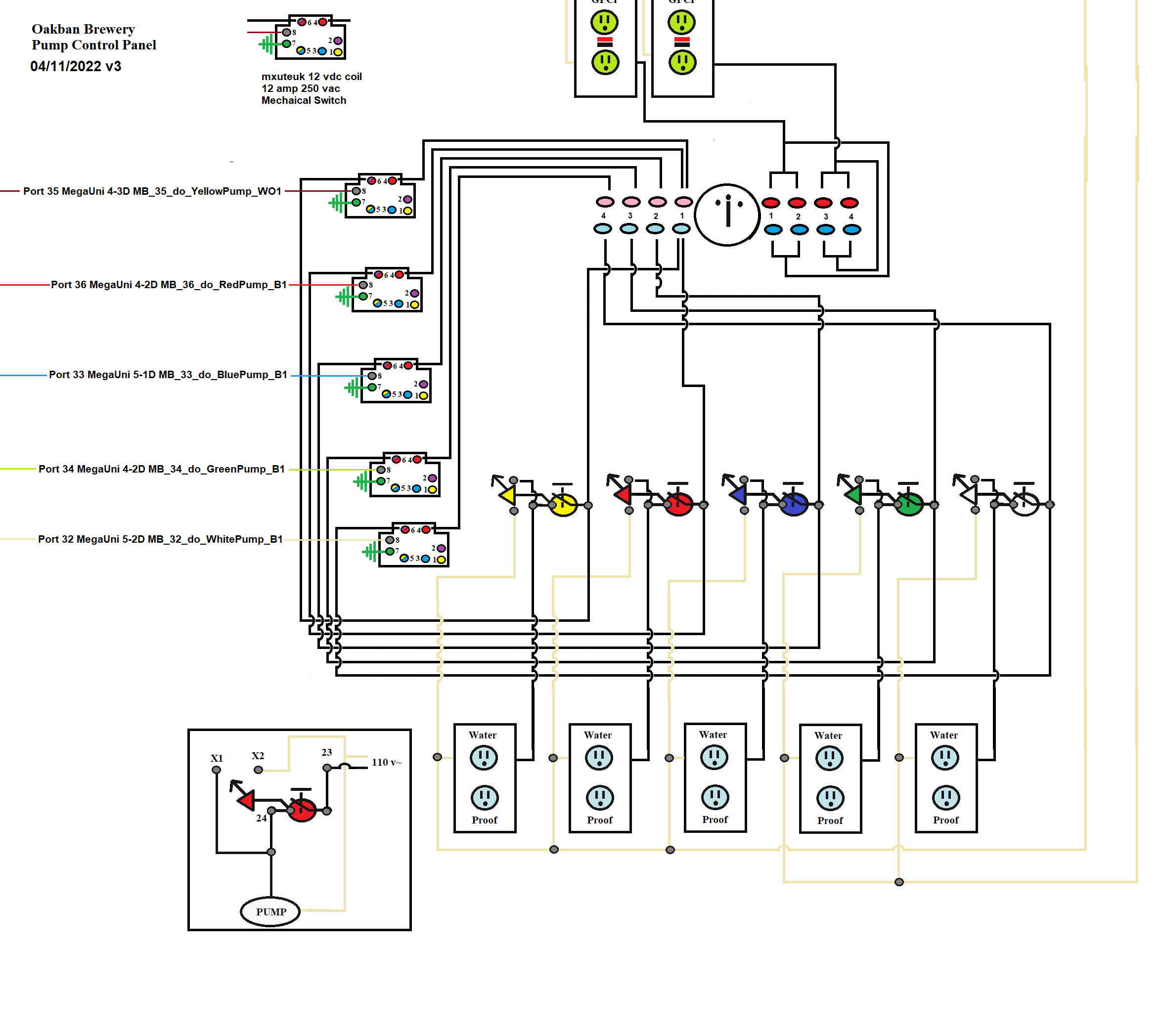
My final plan for my five Blickmann Riptide Pumps. I have total manual control and auto control via a rotary switch. I have colored LED maintained switches that also provide individual control of each pump.

I have found that when priming pumps, a manual control via the maintained switch is very handy.

In addition, when transferring Wort from the MLT to the Brew Kettle (vias my Blue Pump), we need to manually shut off the pump via the maintained switch when the Wort is transferred and the Pump starts to cavitate. The same is true with the red and yellow Pumps when transferring Wort to the Fermentors.

Since I was getting some feed back on the LEDs in the auto mode, I elected to go with 12 vdc coil mechanical contractor switches instead of SSRs. These eliminates some complexity as I can drive them directly with the Mega UNI. In fact, since I can use 12 vdc coil mechanical contractor switches in stead of SSRs, I will only have 4 proportional controllers for my Electric Elements and no other SSRs. Thanks for the advice @BrunDog for using these instead of 24 vac Contactors. Any Comments?
pump Box6.png
 
Do I need to wire the aref pin for Brucontrol? Your schematic shows tying it to 5v on a mega. Typically I would not hook up aref unless I wanted a different reference voltage than the interface internal reference.
 
Does anyone have a brewday flow chart for how you have set up brucontrol? I don't want all the script detail because I think the differences between systems will make it not so valuable. I have seen some nice setups with timers for each step and would like to see how it was done.
 
I have this alarm script monitoring fermenter temps which I have set to email. My issue is that when I have a temp issue I receive way too many emails. Can someone assist with a good way to quiet this? Maybe with a wait command?


Code:
[Alarm-Setup]
new value alarm_low
new value alarm_high
new value alarm_counter
new value alarm_threshold
new string FV-1_alarm_status

"FV-1" target = "FV-1 PT100" value
alarm_low = "FV-1" target - 3
alarm_high = "FV-1" target + 3
alarm_threshold = 6 					// Timespan multiplier for sleep command
alarm_counter precision = 0

	[Alarm-Check]
if "FV-1 PT100" value <= "FV-1" target
	if "FV-1 PT100" value > alarm_low
	FV-1_alarm_status = "SYSTEM OK"
	"FV-1 TEMP ALARM" active = false
	sleep 500
	goto "Alarm-Check"
	endif
endif

if "FV-1 PT100" value >= "FV-1" target
	if "FV-1 PT100" value < alarm_high
	FV-1_alarm_status = "SYSTEM OK"
	sleep 500
	goto "Alarm-Check"
	endif
endif

	[Alarm-Count]
if "FV-1 PT100" value <= alarm_low
	if alarm_counter < alarm_threshold
	alarm_counter += 1
	print alarm_counter
	"FV-1 TEMP ALARM" active = false
	FV-1_alarm_status = "ALARM DELAY"
	sleep 10000					// Defines alarm_threshold timespan
	goto "Alarm-Count"
	endif
endif

if "FV-1 PT100" value >= alarm_high
	if alarm_counter < alarm_threshold
	alarm_counter += 1
	print alarm_counter
	"FV-1 TEMP ALARM" active = false
	FV-1_alarm_status = "ALARM DELAY"
	sleep 10000					// Defines alarm_threshold timespan
	goto "Alarm-Count"
	endif
endif

	[Alarm-Fault]
if "FV-1 PT100" value <= alarm_low
	"FV-1 TEMP ALARM" active = true
	FV-1_alarm_status = "LOW FV TEMP"
	sleep 10000
	goto "Alarm-Count" 
endif

if "FV-1 PT100" value >= alarm_high
	"FV-1 TEMP ALARM" active = true
	FV-1_alarm_status = "HIGH FV TEMP"
	sleep 10000
	goto "Alarm-Count"
else
	alarm_counter = 0
	goto "Alarm-Check"
endif
 
Does anyone have a brewday flow chart for how you have set up brucontrol? I don't want all the script detail because I think the differences between systems will make it not so valuable. I have seen some nice setups with timers for each step and would like to see how it was done.
What I did was to write each step in my brew day no matter if something I could automate or not. I created steps in the scripts for each step and automate every one I could. In some cases, I did leave manual steps (such as turning on an Element after filling the HLT with water that I plan to automate later.

I created a switch (you could use a button) on my main Brew Page that has to be clicked to advance the script and do something (such as turn on the HLT Elements) when IO want or need to do something manually.

I control the flow with an incremental global value that allows me to control the flow (and skip thongs if conditions are met). The switch increments the value if needed. Automated items increment in the
script.

My plan started like this.

1. Fill Radiator ( a small HLT that I use for the HERMS bath) Auto stepped by a Timer (flow meter in the future). I can override the time with my switch.)
2. Fill HLT ( a Large HLT) Auto stepped by a Timer (flow meter in the future). I can override the time with my switch.)
3. Turn on Electric Elements. This is now a manual step that I must click the switch to advance and turn on the Elements. I plan to automate in the future.
4. Radiator at Temp and maintained.
5. HLT at Temp and maintained.
6. Transfer Strike Water to MLT. This is a manual step where I must click the switch to set the valves and turn on the appropriate pump. This will always be a manual step as it is the real start of a Brew Day as we heat the water during the night and come into the brewery with the water to transfer.
There is a Branch here in my Scripts if the Water needs to be Distilled for a lager, I heat the distilled water in my Radiator and will transfer that to the MLT and then refill the Radiator from the HLT.
The transfer is based on time and will auto advance (flow meter in the future). I can overide the Timer with my switch.
7. Wait for Strike ( we send the Strike Water a little hotter than necessary and let it cool to the strike.) { Much easier to cool that heat s trike water. We have a pause where we can fix if too low in the script.
8. Add Grain (Manual step)
9. Set hoses and pumps for Vorluft (Manual step and will always be.)
10. Vorluft (Auto by Timer)
11. Reset hoses for HERMS
12. Start Mash Timer (This turns on the pumps and sets the valves.
13. Mash step 1 (Auto by Timer) (generally skipped by advancing as timer is already at target)
14. Mash Step 2 (Auto by Timer) (generally skipped by advancing as timer is already at target)
15. Mash Step 3 (Auto by Timer)
16. 10 Minute Warning (Auto by Timer)
17. 1 Minute Warning (Auto by Timer)
18. Mash Over Alarm. (Auto by Timer) Turns off Pumps and heaters. Sets Valves from HERMS to Transfer to Brew Kettle.
19. Transfer First Run to Brew Kettle. Manual Step
20. First Run Transfer Complete

and so on. I then went back and added additional and intermediate steps.

1. Set Valves to Add Radiator Water. Manual Advance by Switch to start pre brew day.
1a. Branch if Lager and Distilled Water. I have a lot of globals for the recipe we are doing and one global is Distill or Not and the branch selected is by that global. If yes, do 1a.) Advance by Switch after adding Distilled water to the Radiator).
1b. If no, open Fill Valve.
1c. Time water to HLT (Flow meter in the Future). Wait Timer to advance.
1 c1. Override Timer by Switch if desired . Jumps to 3.
2. Shut off Fill Valve
3. Radiator Filled (Message on Screen and after a short delay, Auto Advance)
4. Set Valves to fill HLT (Auto Advance)
5. Open Fill Valve. Auto Advance
Time water to HLT (Flow meter in the Future). Wait Timer to advance.
5 a. Override Timer by Switch if desired.
and so on.
 
Back
Top