bmarley5780
Well-Known Member
How many wires to power your PID?

I think the temp of boiling wort will be pretty homogenous.
I've got a fairly accurate digital with a LONG probe. Moving it around the kettle it's easy to find 10+ degree variances. Sorry if you previously mentioned - whats the need for temperature monitoring in the kettle again?

The purpose of a thermocouple in the kettle? Well, the PID wont operate without a signal from the thermocouple #1. #2 it will be nice to monitor the temp of the COOLING wort as the immersion chiller does its thing.


I dont see why not... assuming of course that I do not kill myself doing this in the coming days!

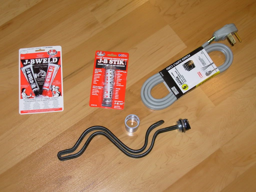
I used a dremmel (sp?) to cut my control box. Worked really well but a hot knife should work too.... I am heading out to buy a hot knife to make the precise cuts in my control box housing for switches and outlets.
HEY, thanks MIKE! I am guessing at the percentages since I have never used a PID for a BK. I generally get about 1.4 gallons of boil off when using a propane burner, thanks for giving me a starting point for the first brew!
Are you using a 5500W element as well for the boil? Are you also brewing 5 gallon batches?
.
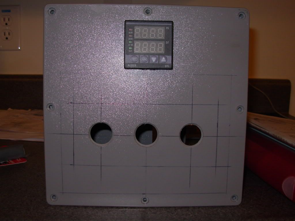
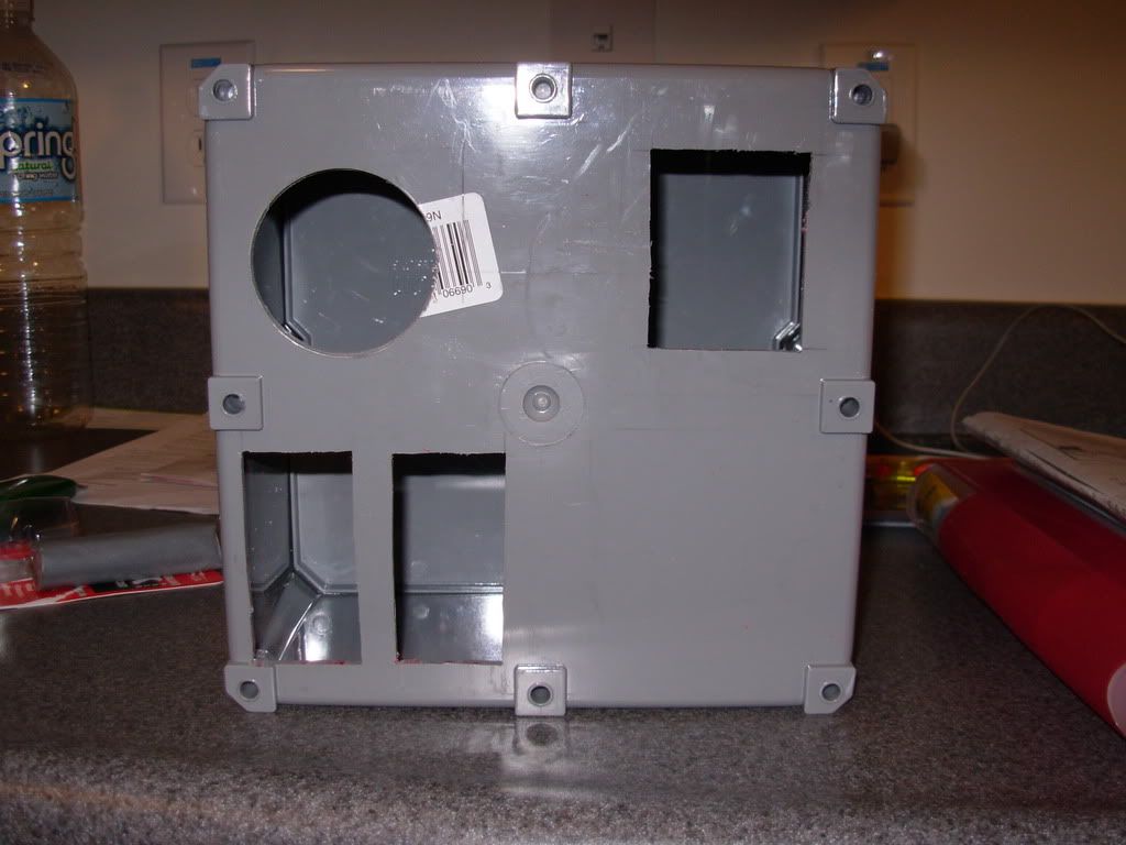
FYI, when wiring THIS box (8x8x4) you need to use 12awg wire where possible, only use the 10awg where needed.(ie. the 240VAC switch and outlet) The box is tight, this wire is rigid, do yourself a favor!

I would suggest that anyone else doing this build when I am finished, buys a 12x12x6 junction box. The 8x8x4 is large enough, but it is extremely tight and requires some very dextrous fingers!
+1 from me as well!
You have inspired me to order a 40A SSR from e-bay last night (with included heatsink) for $19 that I am planning to control from an old PLC i had laying around. (I will program my own logic to do the PWM of the heater element).
Just need to scrape up the cash for the 30A 240V GFCI!
Thanks!
You're using stranded wire, right? In such a tight space, even stranded will be stiff. My "control box" is part of the sculpture and is about 18x18x12, so I had a bit more room. I have seen other examples, where all the 120V stuff is in one box with DC lines ran to all the 240V stuff in another box, I suppose that would make things somewhat easier.
You may want to double check that SSR... is it DC or AC? I have seen many DC SSRs on EBAY with heat sinks.
In case you care, I use 2 techniques when actually using my electric BK. Since you have same PID you can probably do the same:
When I am going to be around to watch BK closely, I set it to manual mode 100%. Since I batch sparge, I do this at first run-off. Usually I'm about to a boil when the second sparge is done (I generally use 2 equal sparges).
If I'm not going to be watching closely (I'm always in the basement, but I may be tending to kids, racking something, eating, etc.) I set it to Auto around 200 degrees. I do this after first run off. I can then do whatever I need to do, and come back to the BK. It's usually holding steady at 200, then I'll flip to manual 100%. Only takes a few minutes to get boiling. This is what I really like about electric, I don't have to watch it like a hawk every second. (Disclaimer: pay attention, don't follow my example, etc.)
I can usually then turn the PID to manual 60% or so to maintain my boil in my insulated BK. It has a single layer of Reflectix on in. I probably need to add one more layer, as it's pretty warm to the touch when boiling - I may could cut it down to 50% or so. When I recirculated through my plate chiller to sanitize it, I bump it up to 75% to overcome the slight heat loss for about 5 minutes, then turn it back down to 60%.
Electric brewing rules! It took me about a year of piecing together info before I built mine, but I can't imagine it any other way. I'm sure you will enjoy it.


![Craft A Brew - Safale BE-256 Yeast - Fermentis - Belgian Ale Dry Yeast - For Belgian & Strong Ales - Ingredients for Home Brewing - Beer Making Supplies - [3 Pack]](https://m.media-amazon.com/images/I/51bcKEwQmWL._SL500_.jpg)


