There is no time scale on that graph. Anyway, not sure it matters but the graph shows an unstable system, which is an incorrectly tuned PID system. Those coefficients are the default so they should work with a moderately sized system (enough thermal mass, which yours has).
You are using an out of date browser. It may not display this or other websites correctly.
You should upgrade or use an alternative browser.
You should upgrade or use an alternative browser.
BCS 2 Vessel No Sparge Garage Brewery Build
- Thread starter poptarts
- Start date

Help Support Homebrew Talk:
This site may earn a commission from merchant affiliate
links, including eBay, Amazon, and others.
OP
OP
poptarts
Well-Known Member
There is no time scale on that graph. Anyway, not sure it matters but the graph shows an unstable system, which is an incorrectly tuned PID system. Those coefficients are the default so they should work with a moderately sized system (enough thermal mass, which yours has).
yea I believe each grid is 5 minutes. But yea I think we can all agree its not even close to intune.
OP
OP
poptarts
Well-Known Member
http://m.eet.com/media/1112634/f-wescot.pdf
This is nice, I like this. Explains PID without all the calculus.
This is nice, I like this. Explains PID without all the calculus.
You don't need to understand how a PID works. If you want to do a basic tune, I recommend the Ziegler-Nichols method: https://www.reddit.com/r/StrangeBrew/comments/3dnd3n/zieglernichols_pid_tuning/
Null the derivative and integral coefficients. Slowly increase your proportional until you get an oscillation. Measure and tune from there.
Null the derivative and integral coefficients. Slowly increase your proportional until you get an oscillation. Measure and tune from there.
Can you explain what the integral clamps do?
Something like this, starting from the algorithm from the BCS wiki:
Code:
pid_output = pTerm + iTerm - dTerm;

where
pTerm = pGain * err;
iTerm = iGain * iState;
dTerm = dGain * (curr_temp - previous_temp);
The pTerm is simply the difference in the setpoint and actual temperature multiplied by some factor. For example lets say the setpoint is 152 and the actual temperature is 150, and we are using the default gains, the pTerm would = (20 * (152-150)) = 20*2 = 40% duty cycle. The iTerm would = (0.5 * (152-150)) + previous_iTerm = previous_iTerm + 1% duty cycle. Let's forget about the dTerm for the moment.
You can see that the iTerm accumulates. If we started out at a real low temperature or we're climbing slowly, the iTerm *by it self* could grow to 200+% duty cycle or what ever. Lets say our actual temp is now at 153, the pTerm would calculate to (20*-1)=-20% duty cycle but without limits the accumulated iTerm could be at +1,000% duty cycle or even higher! In this situation it might take a really long time for the iTerm to come back down to a reasonable level if it's only coming down at (0.5*-1)=-0.5% at a time. This is called windup. The integral clamp allows you to set upper and lower bounds to the iTerm and help mitigate windup.
Code:
pid_output = pTerm + iTerm - dTerm;

where
pTerm = pGain * err;

iTerm = iGain * iState;
  if iTerm < lower_i_limit then
    iTerm = lower_i_limit
  else if iTerm > upper_i_limit then
    iTerm = upper_i_limit
  end if

dTerm = dGain * (curr_temp - previous_temp);I did see the wiki and am going to be mucking with it more tonight for sure. Can you explain what the integral clamps do? I don't understand them. I believe I understand the pulse ones but not the integral limits.
The integral has a tendency to "wind up". This is when the temp has been below the setpoint for a while and the integral value has reached its max. Once you get above the setpoint the output will still be on until the integral unwinds. This will cause your overshoot to be larger and longer in duration. By limiting the max of the integral it won't windup as much and therefore will take less time to unwind during the initial overshoot.
I set the min integral to 0 because we will never need a negative steady state integral. By letting the integral go negative during the overshoot, it will take longer for it to turn positive again after the temp falls back below the setpoint after the initial overshoot.
Long story short the integral clamps are used to reduce overshoot and settling times.


$172.35
2 Inch Tri Clamp Keg Manifold With Ball Lock Posts, Pressure Gauge, PRV (0-30 PSI) – Homebrew, Fermentation, Kegging System
wuhanshijiayangzhiyimaoyiyouxiangongsi


$58.16
HUIZHUGS Brewing Equipment Keg Ball Lock Faucet 30cm Reinforced Silicone Hose Secondary Fermentation Homebrew Kegging Brewing Equipment
xiangshuizhenzhanglingfengshop


$7.79 ($7.79 / Count)
Craft A Brew - LalBrew Voss™ - Kveik Ale Yeast - For Craft Lagers - Ingredients for Home Brewing - Beer Making Supplies - (1 Pack)
Craft a Brew


$53.24
1pc Hose Barb/MFL 1.5" Tri Clamp to Ball Lock Post Liquid Gas Homebrew Kegging Fermentation Parts Brewer Hardware SUS304(Liquid Hose Barb)
yunchengshiyanhuqucuichendianzishangwuyouxiangongsi


![Craft A Brew - Safale S-04 Dry Yeast - Fermentis - English Ale Dry Yeast - For English and American Ales and Hard Apple Ciders - Ingredients for Home Brewing - Beer Making Supplies - [1 Pack]](https://m.media-amazon.com/images/I/41fVGNh6JfL._SL500_.jpg)
$6.95 ($17.38 / Ounce)
$7.47 ($18.68 / Ounce)
Craft A Brew - Safale S-04 Dry Yeast - Fermentis - English Ale Dry Yeast - For English and American Ales and Hard Apple Ciders - Ingredients for Home Brewing - Beer Making Supplies - [1 Pack]
Hobby Homebrew


$39.22 ($39.22 / Count)
Brewer's Best Home Brew Beer Ingredient Kit - 5 Gallon (Mexican Cerveza)
Amazon.com

$33.95
Five Star - 6022b_ - Star San - 32 Ounce - High Foaming Sanitizer
Bridgeview Beer and Wine Supply


$10.99 ($31.16 / Ounce)
Hornindal Kveik Yeast for Homebrewing - Mead, Cider, Wine, Beer - 10g Packet - Saccharomyces Cerevisiae - Sold by Shadowhive.com
Shadowhive


$53.24
1pc Hose Barb/MFL 1.5" Tri Clamp to Ball Lock Post Liquid Gas Homebrew Kegging Fermentation Parts Brewer Hardware SUS304(Gas MFL)
Guangshui Weilu You Trading Co., Ltd


$33.99 ($17.00 / Count)
$41.99 ($21.00 / Count)
2 Pack 1 Gallon Large Fermentation Jars with 3 Airlocks and 2 SCREW Lids(100% Airtight Heavy Duty Lid w Silicone) - Wide Mouth Glass Jars w Scale Mark - Pickle Jars for Sauerkraut, Sourdough Starter
Qianfenie Direct

$22.00 ($623.23 / Ounce)
AMZLMPKNTW Ball Lock Sample Faucet 30cm Reinforced Silicone Hose Secondary Fermentation Homebrew Kegging joyful
无为中南商贸有限公司

$176.97
1pc Commercial Keg Manifold 2" Tri Clamp,Ball Lock Tapping Head,Pressure Gauge/Adjustable PRV for Kegging,Fermentation Control
hanhanbaihuoxiaoshoudian
OP
OP
poptarts
Well-Known Member
awesome that was super helpful. they are defaulted to 0-100, I assume this is a decent starting point for this type of system, but now I can tweak them and know what they do if need be.Something like this, starting from the algorithm from the BCS wiki:
Code:pid_output = pTerm + iTerm - dTerm; where pTerm = pGain * err; iTerm = iGain * iState; dTerm = dGain * (curr_temp - previous_temp);
The pTerm is simply the difference in the setpoint and actual temperature multiplied by some factor. For example lets say the setpoint is 152 and the actual temperature is 150, and we are using the default gains, the pTerm would = (20 * (152-150)) = 20*2 = 40% duty cycle. The iTerm would = (0.5 * (152-150)) + previous_iTerm = previous_iTerm + 1% duty cycle. Let's forget about the dTerm for the moment.
You can see that the iTerm accumulates. If we started out at a real low temperature or we're climbing slowly, the iTerm *by it self* could grow to 200+% duty cycle or what ever. Lets say our actual temp is now at 153, the pTerm would calculate to (20*-1)=-20% duty cycle but without limits the iTerm could be at +1,000% duty cycle or even higher! In this situation it might take a really long time for the iTerm to come back down to a reasonable level. This is called windup. The integral clamp allows you to set upper and lower bounds to the iTerm and help mitigate windup.
Code:pid_output = pTerm + iTerm - dTerm; where pTerm = pGain * err; iTerm = iGain * iState; if iTerm < lower_i_limit then iTerm = lower_i_limit else if iTerm > upper_i_limit then iTerm = upper_i_limit end if dTerm = dGain * (curr_temp - previous_temp);
")
OP
OP
poptarts
Well-Known Member
You don't need to understand how a PID works. If you want to do a basic tune, I recommend the Ziegler-Nichols method: https://www.reddit.com/r/StrangeBrew/comments/3dnd3n/zieglernichols_pid_tuning/
Null the derivative and integral coefficients. Slowly increase your proportional until you get an oscillation. Measure and tune from there.
awesome, thanks a ton for the link. Will be giving this a shot.
I set the min integral to 0 because we will never need a negative steady state integral. By letting the integral go negative during the overshoot, it will take longer for it to turn positive again after the temp falls back below the setpoint after the initial overshoot.
This is very sound advice, and I had not considered it before. Since heating or cooling is "one-way", flattening this makes sense.
This is very sound advice, and I had not considered it before. Since heating or cooling is "one-way", flattening this makes sense.
Makes perfect sense.
In the same vein, just off the top of my head, what about setting the upper bound to something around the system's 'maintenance' duty-cycle. Maybe that's a little too subjective.
Makes perfect sense.
In the same vein, just off the top of my head, what about setting the upper bound to something around the system's 'maintenance' duty-cycle. Maybe that's a little too subjective.
I do something similar. I set the upper limit to 2-3 times the steady state integral value. This part is subjective as the steady state value will be different from day to day depending on the ambient temperature.
Carlscan26
Well-Known Member
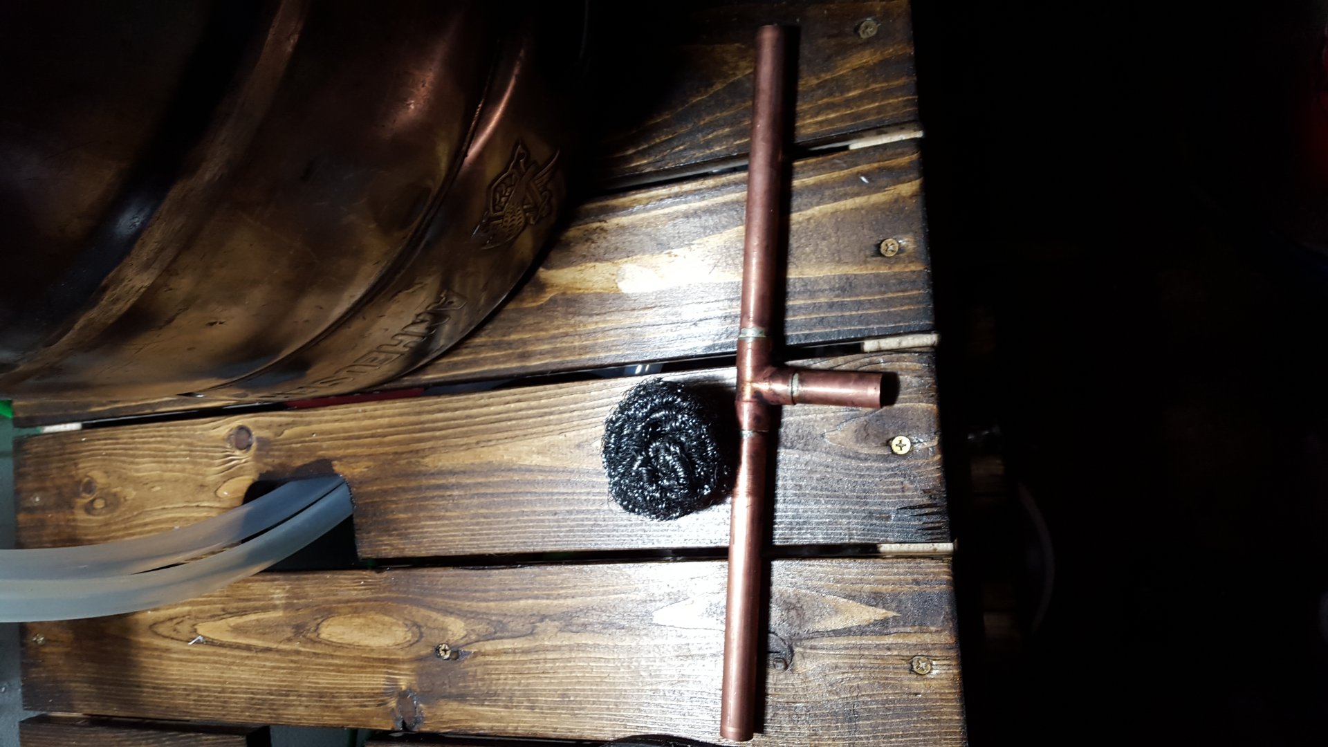
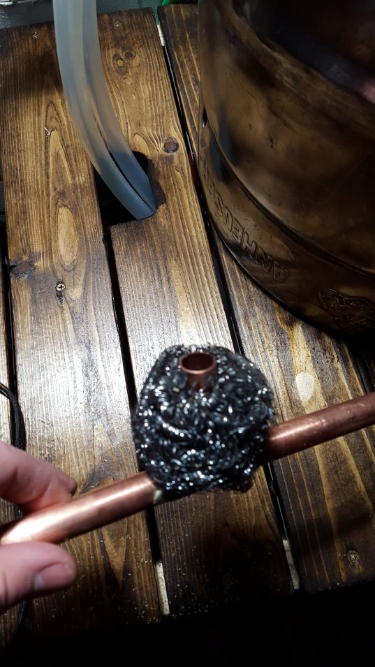
Yea I can get you pics next time im outside. Its basically a Tee made out of 1/2 copper pipe and has a stainless steel wool ball at the base, works and cleans up insanely good and just sits there no installation. The ball does fit 1/2 tubing, its a little big but hose clamps on either side of it keep it from sliding around on the hose. Here is the float and I can get you pics of it on the hose as well.
Thanks!
So does it tie into your drain valve or are you siphoning with it?
OP
OP
poptarts
Well-Known Member
Thanks!
So does it tie into your drain valve or are you siphoning with it?
OP
OP
poptarts
Well-Known Member
Good day all. some cool things happened. My car started (yay weather above -10), IPA has krausen, nothing crazy but its going somewhere. and PID is way way way more in tune. Its still oscillating by about .4 +- around setpoint with waves being around 2 minutes, not super sure how to dial that in but we are way closer. Dialing back max integer to 10 and max pulse to 25 were really helpfull. 'i' was definitely getting wound up and causing the massive overshoots. Probes are reading temp of trusted thermometer as well. So definitely progress. I will brew again this weekend with hopefully better results. And maybe just maybe there is a whisper of a hope the IPA will be drinkable.

Good day all. some cool things happened. My car started (yay weather above -10), IPA has krausen, nothing crazy but its going somewhere. and PID is way way way more in tune. Its still oscillating by about .4 +- around setpoint with waves being around 2 minutes, not super sure how to dial that in but we are way closer. Dialing back max integer to 10 and max pulse to 25 were really helpfull. 'i' was definitely getting wound up and causing the massive overshoots. Probes are reading temp of trusted thermometer as well. So definitely progress. I will brew again this weekend with hopefully better results. And maybe just maybe there is a whisper of a hope the IPA will be drinkable.
Really cool pickup tube you have there!
Did you need to calibrate your temp probes? I have to do mine looks like. I have filled my HLT for clean process today and hopefully can calibrate the temp probes too. One seems off by a good 7º, others might be a little more accurate.
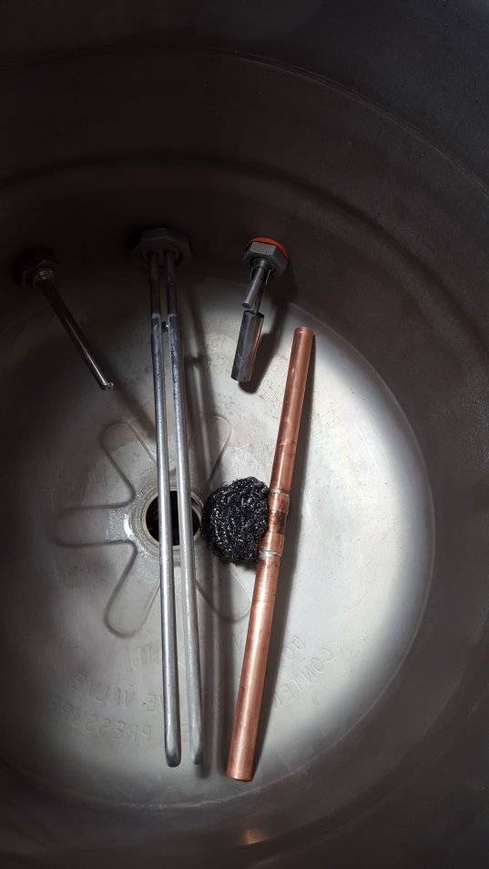
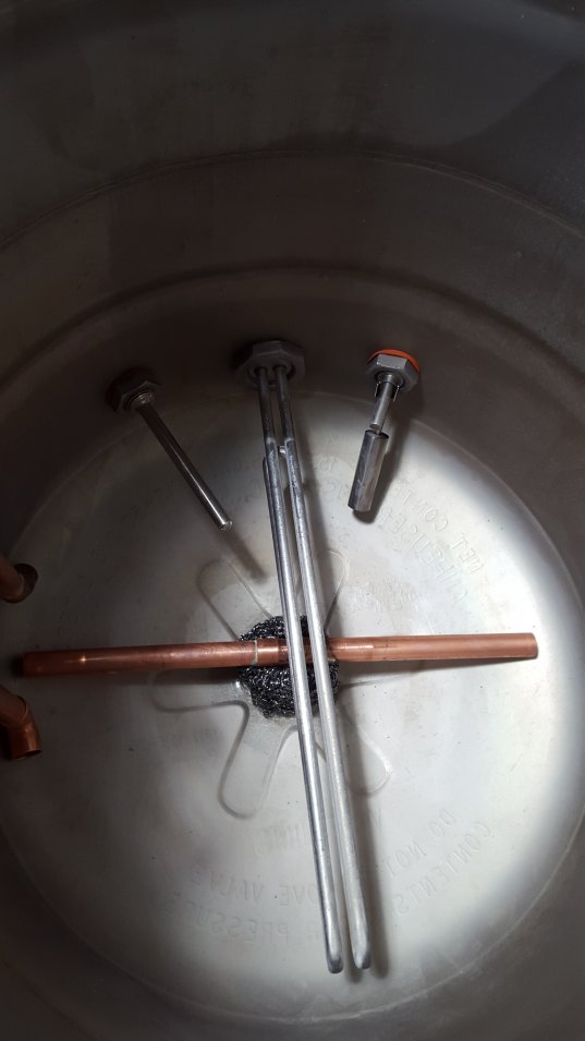
Is your build the one with the float switches in the drain tube? Was wondering if those worked as intended if so.
TD
OP
OP
poptarts
Well-Known Member
Really cool pickup tube you have there!
Did you need to calibrate your temp probes? I have to do mine looks like. I have filled my HLT for clean process today and hopefully can calibrate the temp probes too. One seems off by a good 7º, others might be a little more accurate.
Is your build the one with the float switches in the drain tube? Was wondering if those worked as intended if so.
TD
They came calibrated by brewers hardware, so I haven't touched them. Yep I have the float switches in the Tee below each pot for pump cut offs, they work amazing so far. Even at full open they do not trip until the water is too low. Workes perfect for hands off lautering.
They came calibrated by brewers hardware, so I haven't touched them. Yep I have the float switches in the Tee below each pot for pump cut offs, they work amazing so far. Even at full open they do not trip until the water is too low. Workes perfect for hands off lautering.
BCS uses thermistors right?
OP
OP
poptarts
Well-Known Member
BCS uses thermistors right?
I use these exactly
https://www.brewershardware.com/4-Temperature-Sensor-for-BCS-460.html
and they have these thermistors in them according to brewers hardware.
https://www.brewershardware.com/THERM10KNTC-1.0.html
Certainly not trying to bootleg the thread, but just in case anyone was looking for alternate high tolerance thermistors (0.5%), I used these and they are very consistent/accurate compared to a thermapen and each other: https://www.digikey.com/product-detail/en/MF51E103E3950/317-1305-ND/1191080
Carlscan26
Well-Known Member
So if I understand this design correctly, the liquid drains though the tube ends until the level gets low, then it is strained through the scrubby. Is that correct?
Do tell.
OP
OP
poptarts
Well-Known Member
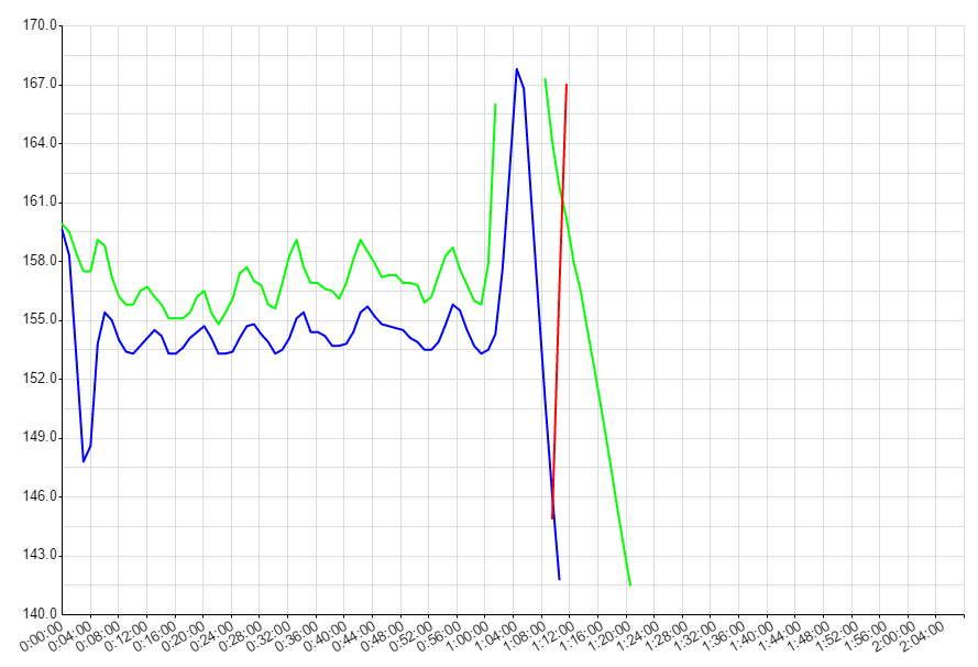
Mash from last brew day; setpoint 154, blue is return, green is MLT. Still has oscillation but nowhere near last time.

I knew it was going to be a bad day when my bcs was reading 2 degrees in the garage. The short version, everything was frozen, so frozen one of the ball valves broke. was able to take it apart and mend it during the mash. Lines apparently didn't drain fully so they had sections of solid ice in them. Ended up doing an hour or so whirlpool because I couldn't thaw the chiller for the life of me. Decided to just rack to carboy and chill in icy water. After cleaning up and taking the chiller inside and thawing it fully sad news was found. There was water left in the outer coil of the chiller that froze and appears to have collapsed the inner tube the wort runs through. Pretty sure its ruined beyond repair. I will cut it open to make sure but sadly I think its dead. I cant blow air through either end, its sealed shut. Here is a pic of the fallen trooper. Loved this chiller, it always worked perfect, 1 pass and done.
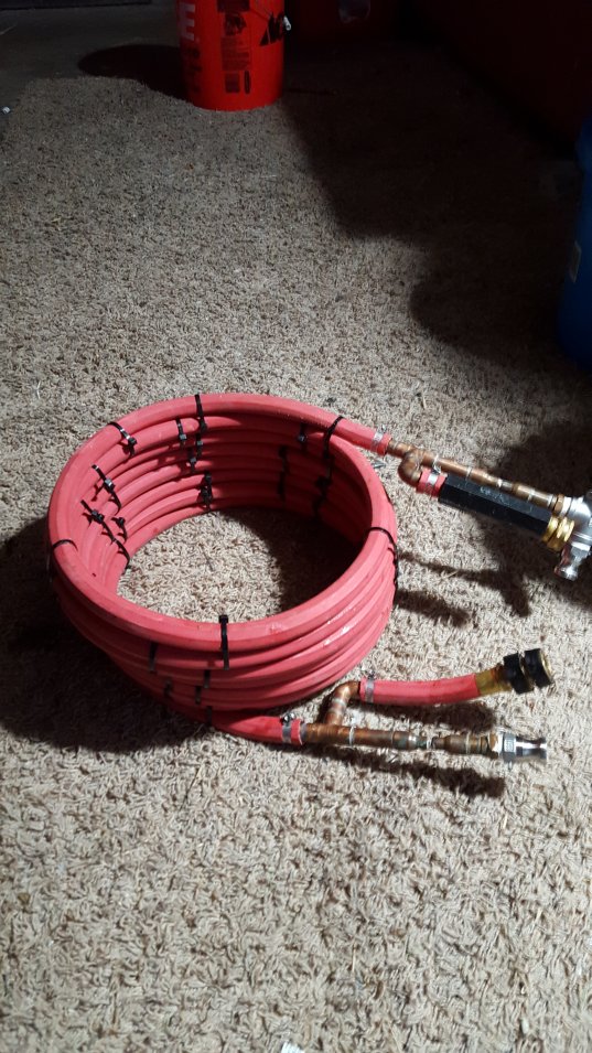
Good news though, Austinhomebrew has a pretty sick deal on counterflows so I picked one of those up. Should be a lot easier to mount and drain. And I learned I think in the winter I need to take the hoses off and let them fully drain, and store the ball valves in open position when not in use. So yea any tips on how to tighten up the PID more or is this about as good as I should expect when its about 150 degreese colder ambient temp.
I knew it was going to be a bad day when my bcs was reading 2 degrees in the garage. The short version, everything was frozen, so frozen one of the ball valves broke. was able to take it apart and mend it during the mash. Lines apparently didn't drain fully so they had sections of solid ice in them. Ended up doing an hour or so whirlpool because I couldn't thaw the chiller for the life of me. Decided to just rack to carboy and chill in icy water. After cleaning up and taking the chiller inside and thawing it fully sad news was found. There was water left in the outer coil of the chiller that froze and appears to have collapsed the inner tube the wort runs through. Pretty sure its ruined beyond repair. I will cut it open to make sure but sadly I think its dead. I cant blow air through either end, its sealed shut. Here is a pic of the fallen trooper. Loved this chiller, it always worked perfect, 1 pass and done.
Good news though, Austinhomebrew has a pretty sick deal on counterflows so I picked one of those up. Should be a lot easier to mount and drain. And I learned I think in the winter I need to take the hoses off and let them fully drain, and store the ball valves in open position when not in use. So yea any tips on how to tighten up the PID more or is this about as good as I should expect when its about 150 degreese colder ambient temp.
ccfoo242
Well-Known Member
Wow! Not a problem I ever considered here in Florida.
Ya... me neever. I guess that is why most in cold Wx try to brew indoors! Sorry about the expansion properties of freezing water!
Regarding the PID loop... something is wrong. It is still unstable (oscillation gets bigger over time), and that is almost hard to do. Also, the response is pretty slow... almost 8 minutes peak to peak. I think your D is too high, but certainly this needs to be tuned. BTW, you could have fixed this by changing it to a fixed duty cycle and modifying it slightly over time yourself. I see you capped the output pulse to 25% - this could be needed but with properly tuned PID this should not be necessary. I don't remember your system - will go back and look and maybe make some recommendations.
Regarding the PID loop... something is wrong. It is still unstable (oscillation gets bigger over time), and that is almost hard to do. Also, the response is pretty slow... almost 8 minutes peak to peak. I think your D is too high, but certainly this needs to be tuned. BTW, you could have fixed this by changing it to a fixed duty cycle and modifying it slightly over time yourself. I see you capped the output pulse to 25% - this could be needed but with properly tuned PID this should not be necessary. I don't remember your system - will go back and look and maybe make some recommendations.
OP
OP
poptarts
Well-Known Member
Ya... me neever. I guess that is why most in cold Wx try to brew indoors! Sorry about the expansion properties of freezing water!
Regarding the PID loop... something is wrong. It is still unstable (oscillation gets bigger over time), and that is almost hard to do. Also, the response is pretty slow... almost 8 minutes peak to peak. I think your D is too high, but certainly this needs to be tuned. BTW, you could have fixed this by changing it to a fixed duty cycle and modifying it slightly over time yourself. I see you capped the output pulse to 25% - this could be needed but with properly tuned PID this should not be necessary. I don't remember your system - will go back and look and maybe make some recommendations.
Yea its definitely better but not ideal. I need to just sit down again with the tuner probably and watch it graph while i tweak. Sadly its like 1 tweak per 20-30 minutes though at the moment so its a slow process.
Similar threads
- Replies
- 11
- Views
- 973
- Replies
- 11
- Views
- 1K

Latest posts
-
-

-

-

-

-
Canned wort: concentrate vs non-concentrate; hot break material
- Latest: EscapeArtistBrewing
-