• Please visit and share your knowledge at our sister communities:
  • If you have not, please join our official Homebrewing Facebook Group!

    Homebrewing Facebook Group

Bad News Brewery - Control Panel

Homebrew Talk

Help Support Homebrew Talk:

This site may earn a commission from merchant affiliate links, including eBay, Amazon, and others.
Alright - I got the switches working. I had run them at 240v, with Hot A to X1 and Hot B to X2 through the NO portion of the switch. So, with the contactor 'leaking' neutral, I wound up getting 120V from X1 to X2. So I changed the feed to X1 to neutral and now the lights only come on with the switch depressed.

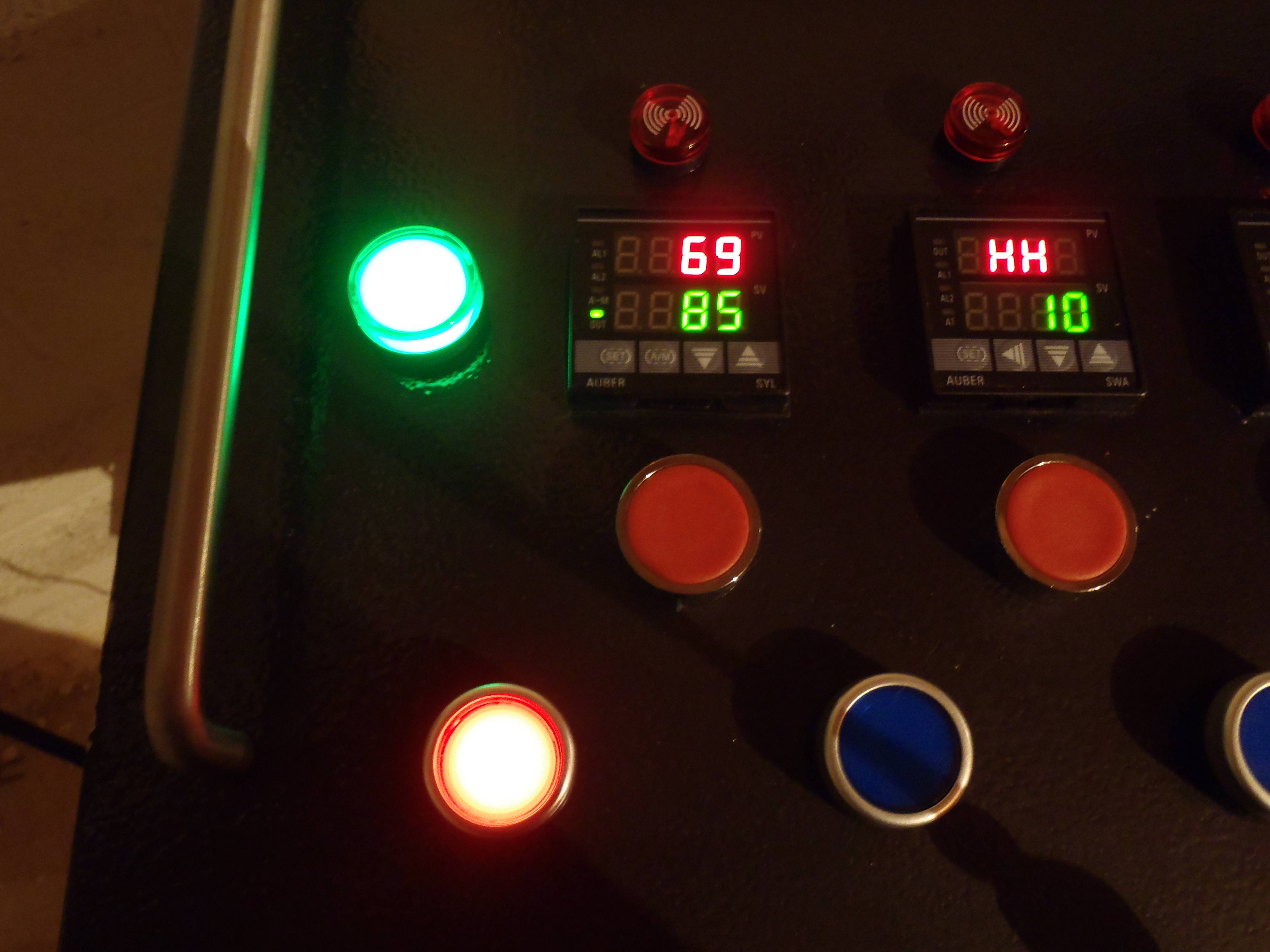
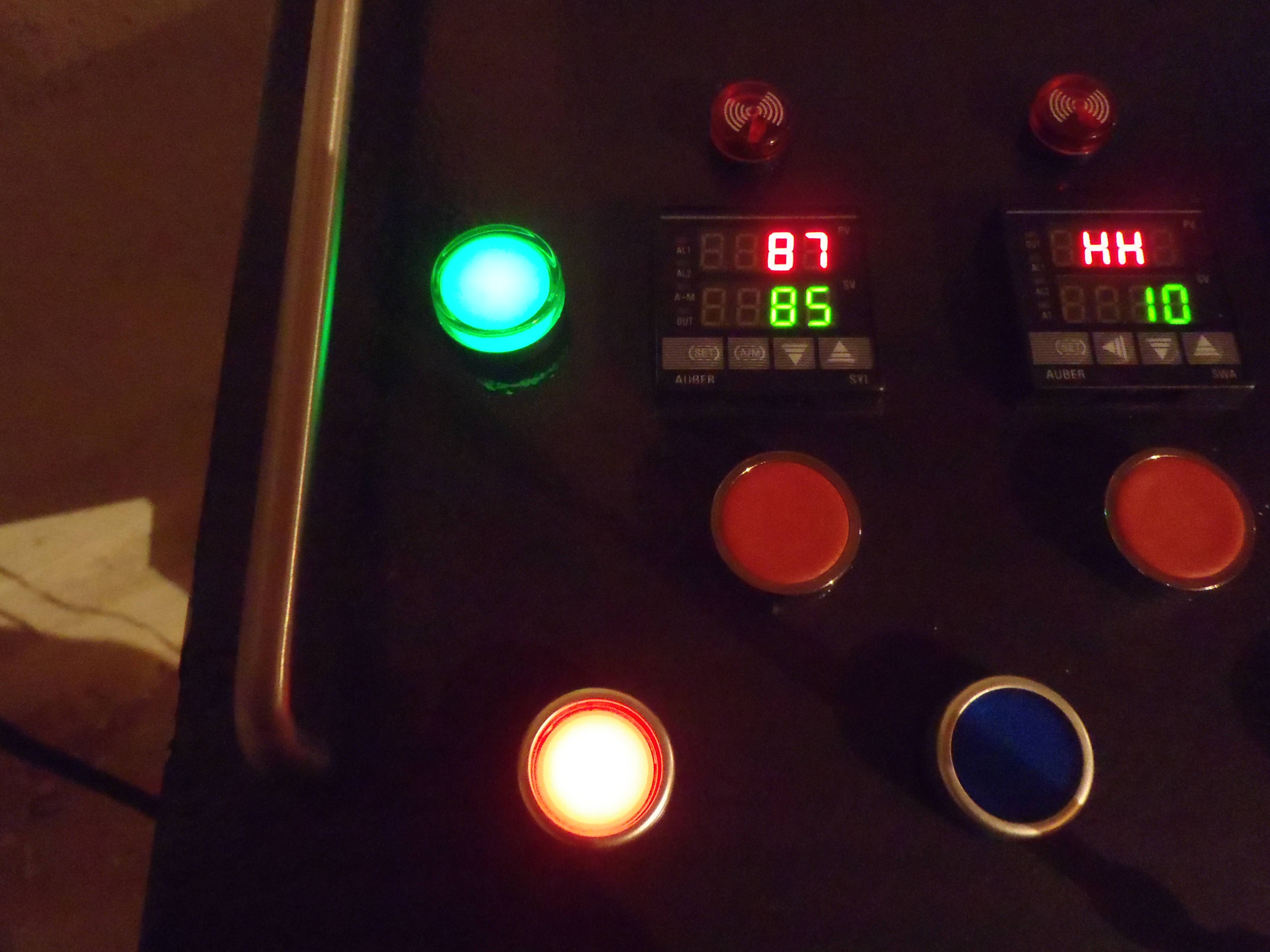
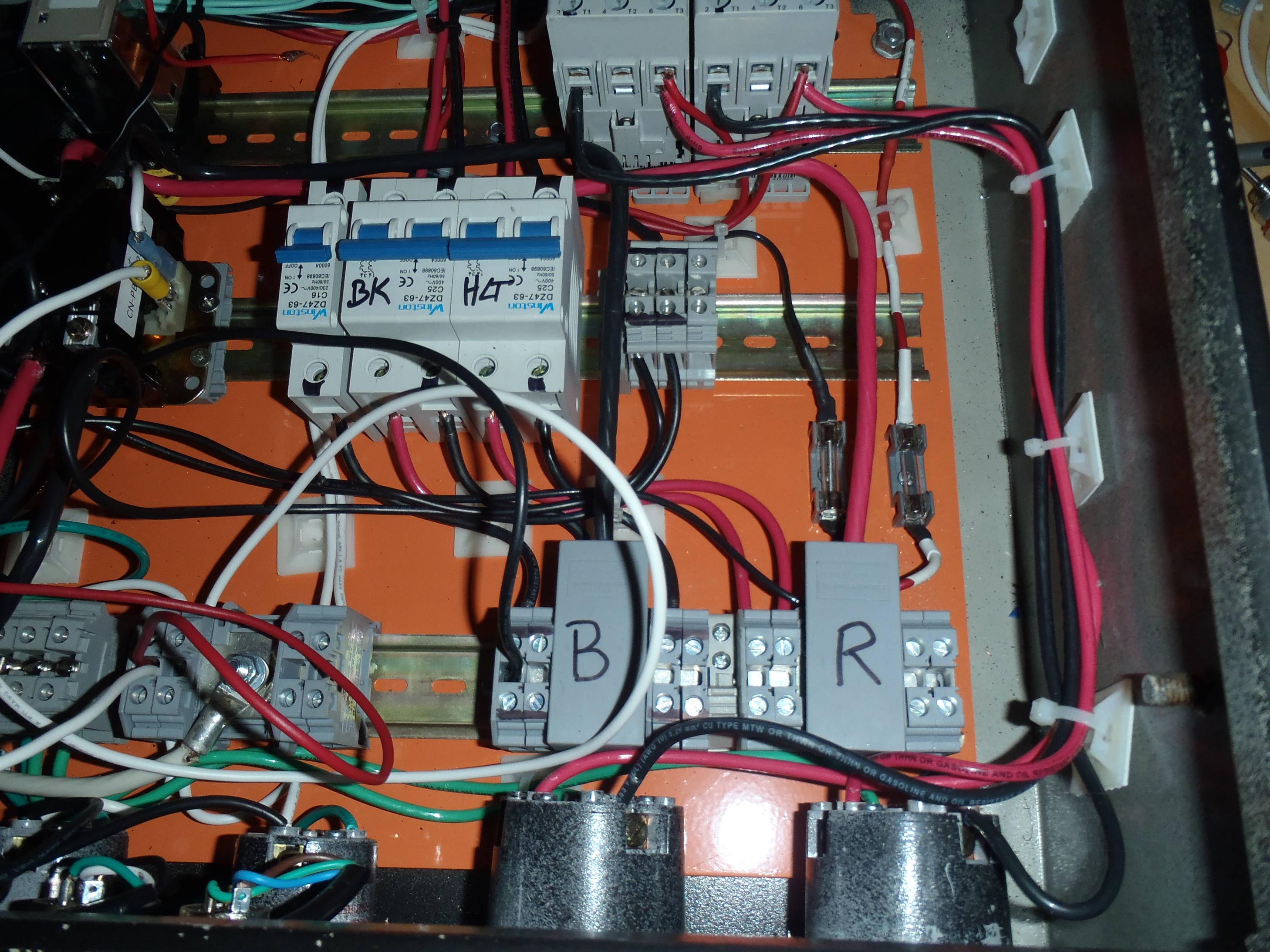
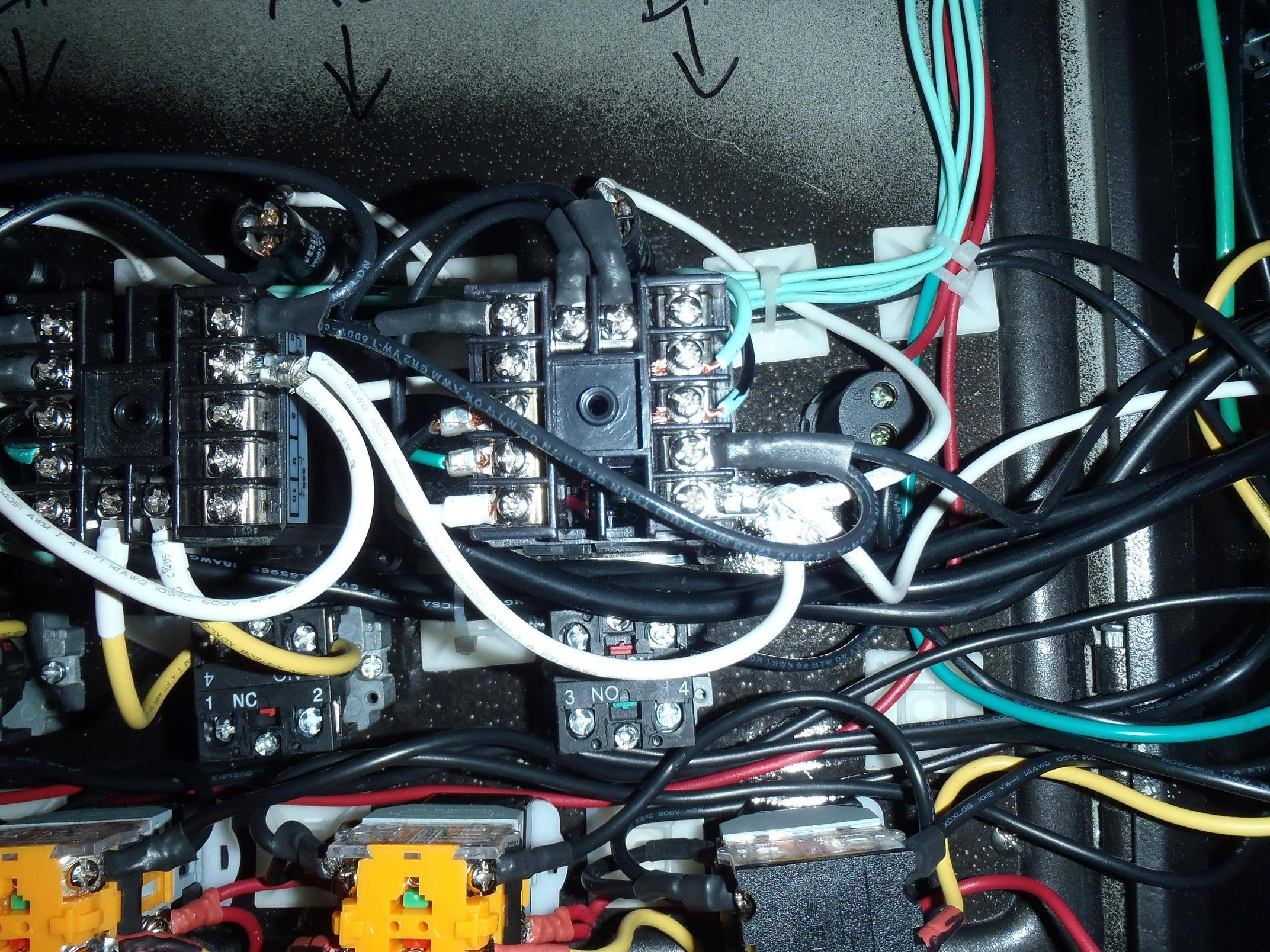
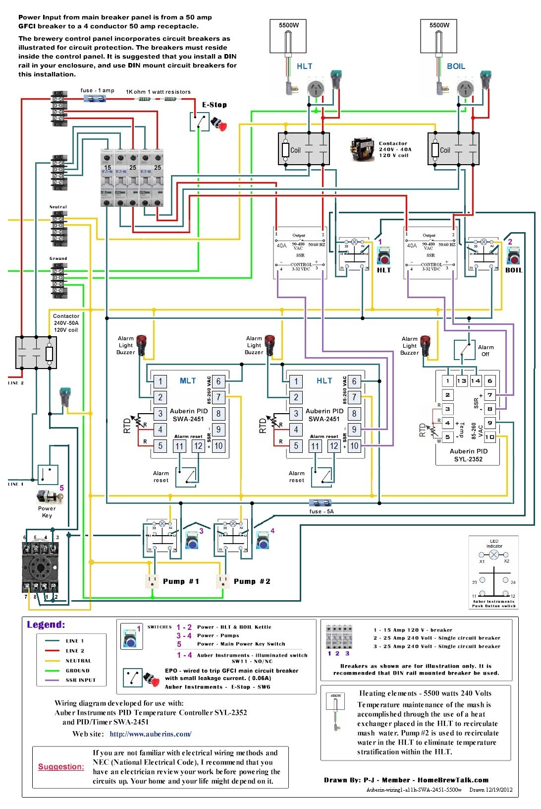
New problem though... the element LEDs come on when the element contactors are turned on, regardless of what the SSR is doing. I run power to the light from the red and black lines downstream of the contactor, just like in my wiring diagram. In theory, the SSR limits the juice flowing to the red line, so it should only turn the LED on when the SSR is switched on.

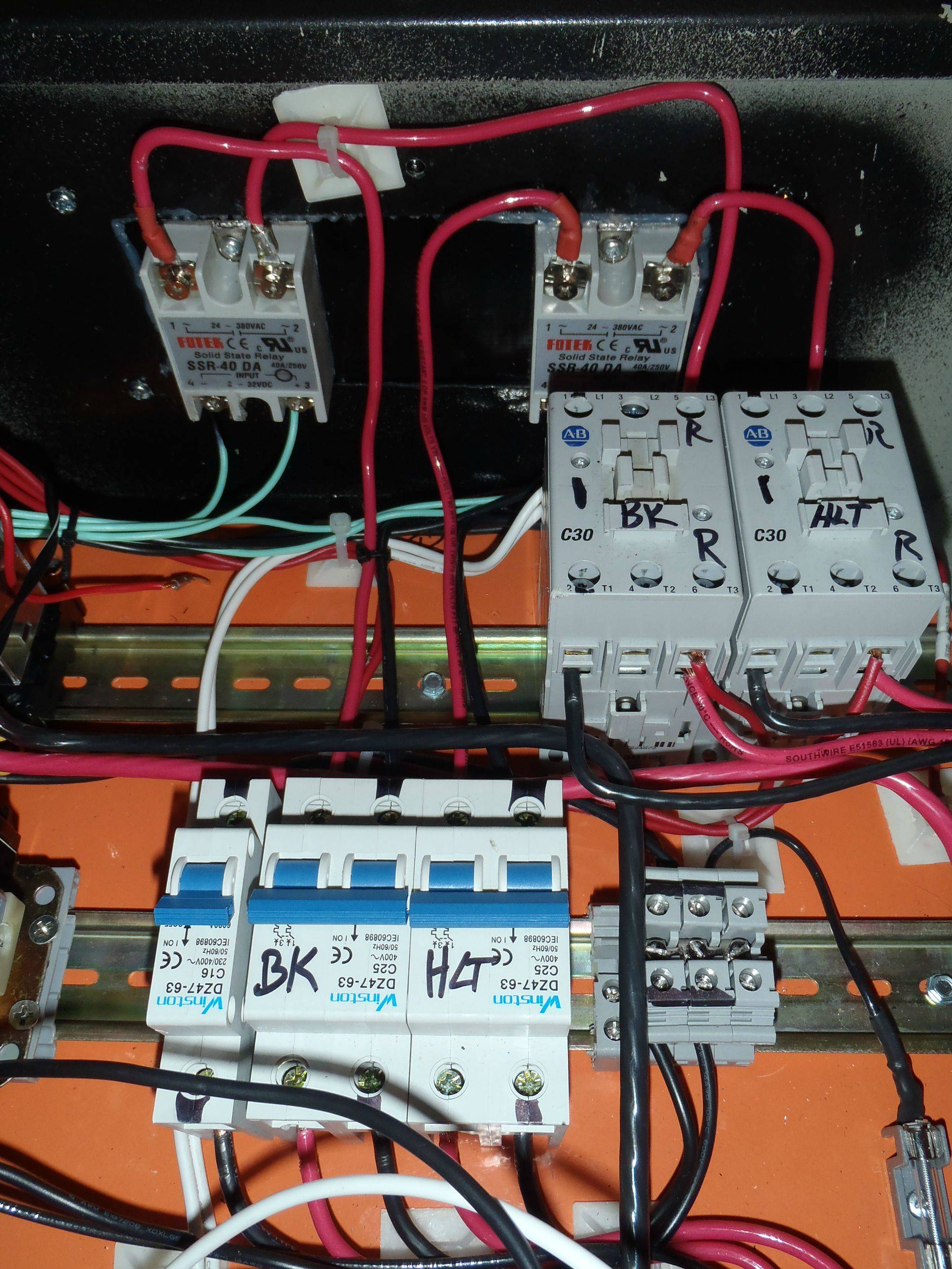
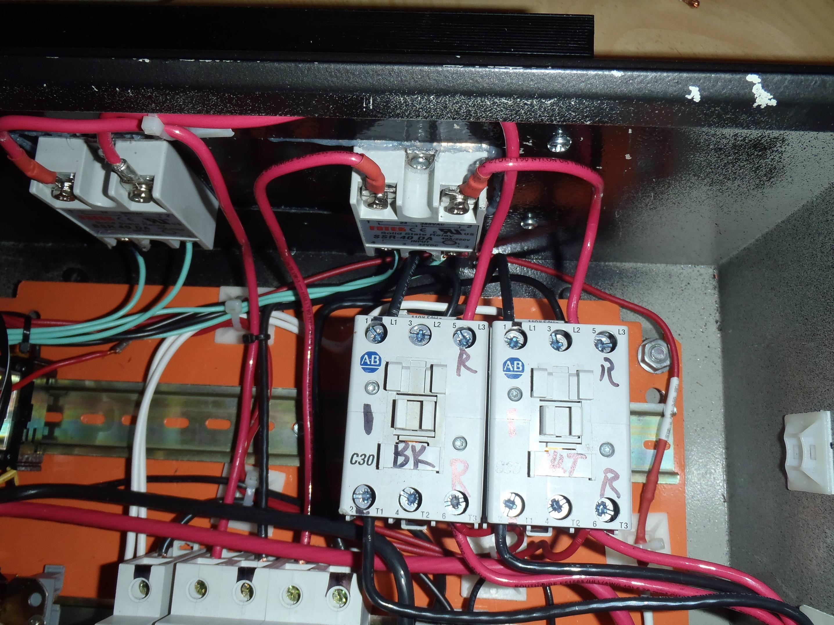
I took some readings to see if I could figure out what was wrong. All measurements taken from the downstream contactor red line to either the white (neutral), black (Hot), and Red (should be zero... red to red...) Here they are:

SSR off / Contactor Open (off) - 115 (W) / 2 (B) / 240 (R)
SSR off / Contactor Closed - 66 (W) / 54 (B) / 185 (R)
SSR on / Contactor Open - 115 (W) / 2 (B) / 240 (R)
SSR on / Contactor Closed - 120 (W) / 240 (B) / 2 (R)

So, in condition 1, it looks like the red line coming off the contactor is acting like a Black line to cause a reading of 240.
Condition 2 - no clue where those numbers are coming from. SSR leakage?
Condition 3 - Black again
Condition 4 - Red - the only time it's actually right.

What the hell is going on here?!
 
I bet if you ran the lights at 120v you would not have that problem. if you're using the ones auber sells I believe they say you can run them at 120v, they'll. Just be a little bit less bright . Id rather just have my lights running off the contactor personally. the pid output light is enough for me. watching the light flutter on & off every few seconds would annoy me.
 
I tried running it at 120v and got the same results as on 240v.

Yes, I could run it such that the green light is on every time the contactor is closed, but I have illuminated buttons, so when I turn on the contactor the LED in the button lights up - I don't need two lights to tell me the contactor is closed.

I want the green LED to light up whenever the PID is firing. I suppose I could just get a 12v LED and run it directly off the SSR output... But the fact remains that the setup I have _SHOULD_ be working, but it isn't, and I can't figure out why. I need the big brains of the E-Brew subforum to help me out of this one... There's a gremlin in my system and I'm not sure where.
 
Here is the latest wiring diagram that P-J and I worked up, to reflect the switches and Safe Start Interlock.

srWfJ.jpg


I'll snap some photos when I get home. I snipped all the zip ties holding the wires nice and neat while trouble shooting, so it's going to be a a bit messy...

-K
 
What grandqueso said. Run them off the contactor.

With power flowing from the terminal strips -> breakers -> SSR -> contactors, it's easy to do. When the SSR closes you'll have power to the light. Just connect another line from your Hot1 and Hot2 at the contactor on the side going out to your 240v power outlets. Don't use a neutral. If they're the Auber lights they can handle 240v.

Or maybe I don't understand what you're trying to accomplish.

The plan shows an illuminated pushbutton for each element and a pilot light at the outlet.

The illuminated pushbutton let's you know the contactor is closed.
The pilot light at the outlet let's you know when the outlet is energized.

Is this not the objective?

You could always not supply power to the lamp in the pushbutton and just use the pilot light at the outlet as an indicator.
 
stlbeer Look at my diagram - that's how I have it, that's how it's wired. The red line runs from the terminal strip -> breaker -> SSR -> contactor -> LED. The black I pulled straight off the terminal strip for wiring purposes (easier), but just for giggles I tried running it directly to the black on the contactor so it goes terminal strip -> contactor -> LED... same exact thing happened.

Don't worry about the illuminated push buttons - they work exactly as planned.
 
So here are some more photos.
First - a picture of the PID with the little green LED indicating that the element is being fired. The big green LED is illuminated (GOOD) and the red LED from the contactor switch is illuminated (Good).

9mozi.jpg


The next image - the PID is NOT firing - no little green LED. The red LED on the contactor is still illuminated, showing that the contactor is still engaged... but the green LED next to the PID is also still on. This should NOT be happening.

WBWrn.jpg


So, here are some photos of the internals. The first picture is a general photo of the contactors, the SSRs, and the breaker. The previous pictures were of the BK (I don't know why, but I wanted my BK on the left, different than most). You can see the red line come from the breaker to the left input on the SSR, then from the right output of the SSR up and over to the input of the contactor. From there, two wires come out - the top 14ga red wire runs over to the LED. The bottom 10ga red goes to the plug. The black line comes out of the breaker and goes straight to the contactor.

kXozM.jpg


Next is a picture of the same but looking straight down. You can see the white 14ga wire running under the black 10ga wire - that goes straight to Neutral as a home-run, and is for the coil. The 14ga black wire under the 10ga red wire goes to the switch.

1KXw6.jpg


Here is a general snap of the panel area surrounding the contactors:

eIqNz.jpg


And here is a picture of the back of the PID. There's a lot going on in there, but you can see the LED to the right in the photo, with a red 14ga running to the top (that comes from the contactor) and you can kind of see a 14ga black coming out the bottom that runs to the black terminal strip.

xtQAB.jpg


So... what am I doing wrong?
 
Unfortunately I don't know how to fix your problem but I am very interested to see how this works out as I plan to wire a light in system similar to yours.

It does look like the green indicator light changes as far as brightness when the element is firing vs when it is off. Is that the case or does it just look that way in the pictures?

Corey
 
Honestly, some times it does look like it's different, some times not. Couldn't really say for sure.

And it does this on both SSR / contactor combos. So either I have 2 bad SSRs, 2 bad contactors, or I am going crazy.
 
Kevin,

I think: The SSR will pass a very small amount of leakage current when it is not told to fire the element.

The LED indicator light has a power consumption of less than 2 watts.
With 240V that means it will have a current draw of about 0.008 amps.
With that, the LED has a resistance of 30,000 ohms.

I believe there is enouh leakage current to fire the LED.

Now for something to try.
Place a 3000 ohm resistor in parallel with the indicator light. This will allow the draw of .08 amps of current and effectively shunt the indicator lights small current draw. The resistor would need to be about a 200W unit.


I think it is worth a try.

If the indicator light were a incadecent device I think it would operate as expected.

Think about it and give it a try.

Paul
 
P-J,
I'm not sure I understand. Do I need a 3000W resistor or a 200W resistor? In parallel to the LED - are you saying that I should run X1 to X2 around the LED with the resistor, or put the resistor in-line between the contactor and the LED?
-Kevin
 
P-J,
I'm not sure I understand. Do I need a 3000W resistor or a 200W resistor? In parallel to the LED - are you saying that I should run X1 to X2 around the LED with the resistor, or put the resistor in-line between the contactor and the LED?
-Kevin
I blew it. I stated 3000W and it should have been a 3000 ohm resistor. I corrected my post.

Place the resistor in parallel with the LED - not in series. This way the current flows through the LED and the resistor. The resistor will bypass some (most) of the leakage current and prevent it from illuminating.

Don't place it in line with the LED (in series).
 
So something like this? 3k ohm, 200w resistor... at $45 a pop, I might have better luck getting new SSRs - I bought eBay cheap-o's and may be paying the price right now...
 
It looks like from your diagram that you have the SSR, contactor, element, and LED wired the same as Kal's. I would expect that quite a few people have it wired that way in their Kal clones, so it should work. Curious.
 
Wow... a lot of the explanations on that post were horrible, but I think Walker got it on this one. I have been doing all my testing with no element plugged in. I will grab an element and plug it in and if we're right it will act like the resistor P-J was talking about... and my light will be dark until the SSR fires.

If it does end up working out and all this is due to SSR leakage, then my experience should be enough evidence to anyone that an SSR alone is NOT enough. I'll do some testing tomorrow or over the weekend, maybe I'll be brewing in the Mayan after-life!

BINGO.!!!

I was doing mind cramps trying to figure out what was going on. I totally forgot about the element as the "resistor" across the indicator light.

Forget about the resistor suggestion. The element is it!

I just have to say that getting really old just plain sucks.

Plug the element in (Do Not dry fire it) and test it again.

P-J
 
EDIT - Same advice as above - plug in your element.

BTW - I like your terminal blocks for power distribution and those AB contactors. Did those contactors come from Zeus?
 
I had to leave for work before the sun came up, so testing the panel with an element last night / this morning was a no go. I'm anxious to get home and give it a shot. If this does work, it will solve all but the weird voltage readings I was getting. I don't want to fry my multi-meter testing for amperage as it's only rated for 10A, but part of me is thinking that the strange voltages I was picking up has something to do with inductive current from all the other wires running around. I'm willing to guess the voltage is there, but there is zero actual amperage. I suppose I could rig up a little light bulb tester to find out, but if the panel works as designed with the element plugged in, then I won't worry.

stlbeer, yes - I got the two contactors from Zeus. The terminal blocks came from Mouser, here. Part number is CDB6/2, though you can change the second number to give you more terminal blocks (remember, you can plug one in on each side, so the /2 is actually 4 connections).
 
getting some awesome info from you, PJ and kal on all this ebrew stuff...

VS5aC-questions.jpg

forgive my total ignorance,... have some questions on this diagram, starting with a key to the symbols used; have a good idea what some of the symbols are (it's a KETTLE!). If it's been explained before, I must have missed it

I appreciate the help and many thanks in advance
 
First, I'm honored to even be considered among the greats like Kal and P-J, but I leared all my ebrew-how from the greats before me.

Regarding the diagram, I have completed it for you. This was actually my original layout (rough) for my control panel, when I thought I was going to have electrically actuated valves and backlight routing. I made it as a fully operational PowerPoint, so if you want to play around with that send me a PM with your email and I'll send it to you.

Good luck!
-Kevin

VS5aC-questions.jpg
 
Kevin,

I'm still trying to update the master diagram and have another question for you. With the Safe Start relay you illustrate, do you have the actual pin out showing what component connects to each pin? I've searched Kal's site and the net to try and find the actual pinout of that relay. No dice.

I think I have the coil identified as pins 7 & 8. The rest of it????

Is it possible for you to sketch it out for me so that I can better understand the wiring? (Oh & getting really old does suck big time!)

Paul

Relay.jpg
 
P-J,
I am using a MKS2PI-AC120 Omron Industries 8-pin, 2 pole relay. The datasheet is here - the MKS2PI is the top left drawing. I attached a picture of just the pin-out.

Best I can figure, and I'll be the first to admit I have no idea how this magic box works, it actually has 2 coils. It needs to have power to both coils to start, but only needs power to one coil to stay on. So you have the NC terminals providing power to 1 and 2, and the keye'd switch is providing power to 8, then you're golden. I would wager that if you could disconnect 8 after it's powered up, but leave the NC blocks closed, the panel would stay on.

How neutral from 7 powers both coils is beyond me. I really don't understand the drawing. And everything I said above may be totally make believe. For all I know the thing is full of pixie dust and unicorn farts to make it run.

-Kevin

MKS2PI.jpg
 
Wait, I studied it some more and I think I have it. There's one coil, but once it's energized you can drop 120v from Pin 2, and the coil will still be back-fed from the 120v coming through terminal 6, so the coil stays activated. Thus the need to only have 1 neutral, and why 6 and 3 are linked.

Sadly... no unicorns involved.
 
In the name of all that is incredible and amazing about this community... IT WORKS!

Plugged in the element, dropped it into a bucket of water (precarious, I know, but I made sure the wires were clear), turned it on, and nothing... After a little spot checking, I realized the black wire was unplugged - whoops. After double checking all the connections - flipped the switch in super slow motion and much like the pinnacle scene in National Lampoon's Christmas Vacation - BAZAAM! It worked.

:rockin::rockin::rockin::D:D:D

I tested about 10 times, only running the element about 10-15 seconds each time, and every time it worked. What's most impressive / interesting, is that the 3-4 gallons of water I had the element in went from the 50s it started at to just under 100*. I am VERY impressed.

See the attached photos - element on, PID firing, LED lit. Element on, PID not firing, LED not lit. Great success!

Thank you all for your help. I will work to clean up the panel and install the LED backlit face plate, then back to finishing up the kettles.
-Kevin

2012-12-21_19-36-23_42.jpg


2012-12-21_19-36-34_380.jpg
 
Nice man, I'm happy for you! I could feel your frustration and now I'll celebrate your success by cracking a home brew! TGIF! :)
 

Latest posts

Back
Top