• Please visit and share your knowledge at our sister communities:
  • If you have not, please join our official Homebrewing Facebook Group!

    Homebrewing Facebook Group

Bad News Brewery - Control Panel

Homebrew Talk

Help Support Homebrew Talk:

This site may earn a commission from merchant affiliate links, including eBay, Amazon, and others.
I need to brew up some home brew so I have one to crack to celebrate the future success of my peers! This is the new injection of motivation I needed to get back on top of this thing. Cut the panel up some more, drill the keggles some more... it's go time.
 
I'm glad it's finally working for you, I can't wait to see the final product
 
The panel is finished. Need to clean up the wires and mount the face plates better. Then it's time to run through setting up the PIDs and mount it to my ceiling mounted arm.

MmDrk.jpg


The back-lit face plate looks much better than I could have ever imagined. The pictures don't do it justice.

1IhaN.jpg


I'll post photos once I have it fully mounted and running, and then I'll be updating the other parts of the build thread with the finalized product.
-Kevin
 
Wow. That looks really sharp! I can't wait to hear the details for that back lit face plate. I would be really interested in incorporating something like that into my build. Does that fire up/down when you turn the power switch on/off?
 
Does that fire up/down when you turn the power switch on/off?

Yup. So here is the basic workup - I can answer specific questions if you have any.

The LEDs are 20" strips from SuperBrightLEDs.com - and they are in fact SUPER bright. They run off a variable power, but generally around 12vdc. You can buy a 120vac to 12vdc transformer from SuperBright, but I figured 'why bother' as I save every wall-wort / plug in transformer I get, just in case. To the box I went and found one with the right voltage and amperage ratings. Cut the box apart, but off the plug prongs, and soldered new wire leads to where the plugs would have been. I then wired the transformer in to where most people put their power-on LED - basically as an output from the main power contactor. Turn on the box, the contactor closes, the transformer starts putting out 12vdc, the LEDs light up.

The actual plates were self made, too. I thought about going with one of the back-carved acrylic options from BigBlueSaw, but couldn't get their program to work and came up with a better plan. I have a friend that owns one of those do-it-at-home vinyl cutting things. I sent her the files for my logo and text and asked for them to be cut in reverse and also to cut the negative - I didn't want the logo, I wanted everything left over. So basically I had a mirror imaged negative of my logo. Just make sure you leave enough solid border around your logo so you have mounting area and can hide the LEDs.

I got some plexi sheets from the local big-box store. Hit the side of the plexi you want to stick the decal to with a nice coating of windex, then stick the decal down and squeeze out all the bubbles. Once everything is dry, I hit both sides with a frosting spray-paint to help diffuse the light instead of being able to see individual LEDs.

Cut the hole(s) in your box so that the plexi sits over it but the hole is big enough to not block any of the clear area in your logo. Inside the box, I super-glued sections of aluminum L bracket around the hole, so I could mount the LEDs around the perimeter of the cut opening. This allowed me to get the LEDs recessed a little behind the hole to help hide them from direct view. It also let me get the LEDs a little below the opening, so the light was more diffused and less spotty. The LEDs have a sticky back and they go on no problem. I didn't close off the box, so I get a little color bleed between the two sets of LEDs, but it doesn't bother me and adds to the effect. You could close off the back of the box with cardboard, tape, sheet metal - whatever you want.

I think I will attach the plates over the holes using some screws like Kal did on his, but you could just throw a bead of black silicon down and stick them on if you wanted a clean look.

I can do a full write-up with pictures if people really want to know more. It was more work than drilling a hole and wiring up an LED, but I'm of the opinion that it looks WAY better and is much more unique.
-Kevin
 
PJ, by any chance have you been able to update the drawing with the safe start relay in it? I just can't seem to visualize it.
Thanks!
 
P-J and I worked on developing a finalized diagram, which I have posted below (unless, of course, you want me to take it down P-J). If P-J sees this, maybe he can post the updated link to his whiz-bang website where you'll be able to get a bigger version.

One thing to note - P-J found a different relay, which does the exact same thing. He used the relay shown in the second picture below. I wired it up using the relay that Kal used, shown in the third picture. The wiring is almost exactly the same, but to wire it the way I did it (copied Kal's design) check out the final wiring to the relay shown at Kal's website. All the wiring is the same other than which terminals you tie into on the relay.

Works like a charm... Hope this helps.
-Kevin

Auberin-wiring1-a11J-SWA-2451-5500w-Safe-Start.jpg


PJ Relay.jpg


BnB Relay.jpg
 
BadNewsBrewery said:
P-J and I worked on developing a finalized diagram, which I have posted below (unless, of course, you want me to take it down P-J). If P-J sees this, maybe he can post the updated link to his whiz-bang website where you'll be able to get a bigger version.

One thing to note - P-J found a different relay, which does the exact same thing. He used the relay shown in the second picture below. I wired it up using the relay that Kal used, shown in the third picture. The wiring is almost exactly the same, but to wire it the way I did it (copied Kal's design) check out the final wiring to the relay shown at Kal's website. All the wiring is the same other than which terminals you tie into on the relay.

Works like a charm... Hope this helps.
-Kevin

Awesome thanks!
 
P-J and I worked on developing a finalized diagram, which I have posted below (unless, of course, you want me to take it down P-J). If P-J sees this, maybe he can post the updated link to his whiz-bang website where you'll be able to get a bigger version.

One thing to note - P-J found a different relay, which does the exact same thing. He used the relay shown in the second picture below. I wired it up using the relay that Kal used, shown in the third picture. The wiring is almost exactly the same, but to wire it the way I did it (copied Kal's design) check out the final wiring to the relay shown at Kal's website. All the wiring is the same other than which terminals you tie into on the relay.

Works like a charm... Hope this helps.
-Kevin

Do you happen to have a cleaner version of this wiring diagram? When I right-click and "save-as", the quality is horrible. Also, where did you get your safe start relay? Part #? I just blew a paycheck at Amazon.com on plugs, outlets, etc. and now I'm getting ready to order the stuff that goes on the inside of the panel. Thanks!

Chris
 
I hear you on blowing the paycheck over at Amazon, though I spent a lot at Auber, Mouser, eBrewSupply, BrewHardware, and StainlessBrewing.

PM sent about the diagram and part numbers.
-Kevin
 
Hey Kevin,


Did you complete the whole build? Are you brewing successfully on it? What's the update? You left us all in suspense!

-Corey
 
Corey,
Sorry... life got busy, I've been out of the country a bit lately. But yes, 2 batches run through it and still making adjustments. I haven't been able to get the 80-90% mash efficiencies like some, but I'm getting much better results than before, and it makes tasty beer which is the important part to me. It's fast and after running AutoTune, it'll hold within a few tenths of a degree. The hardest part is figuring out what temp to dial the HLT in at for the MLT to be at the ideal temp and to get there quickly.
-Kevin
 
Alright, so I am a bad HBT thread starter / OP and have waited too long to reply... but I'm back.

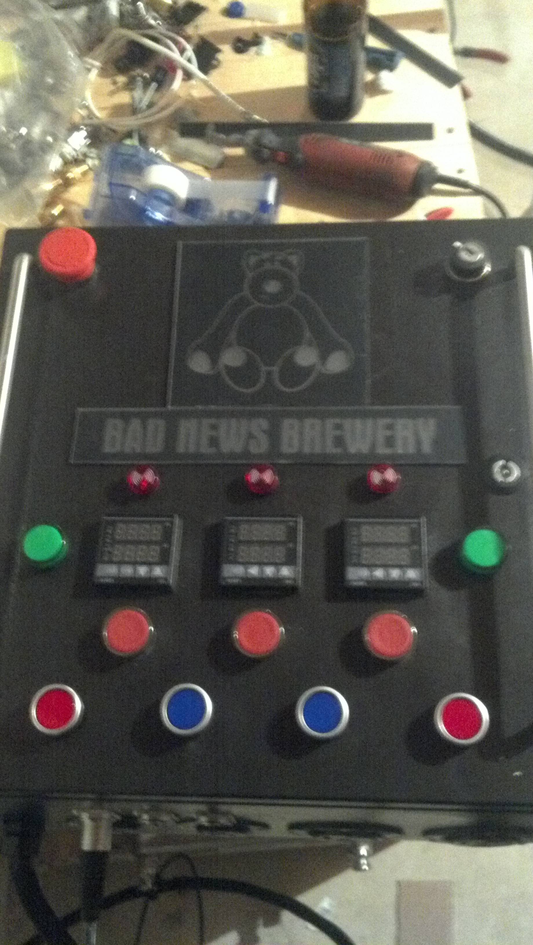
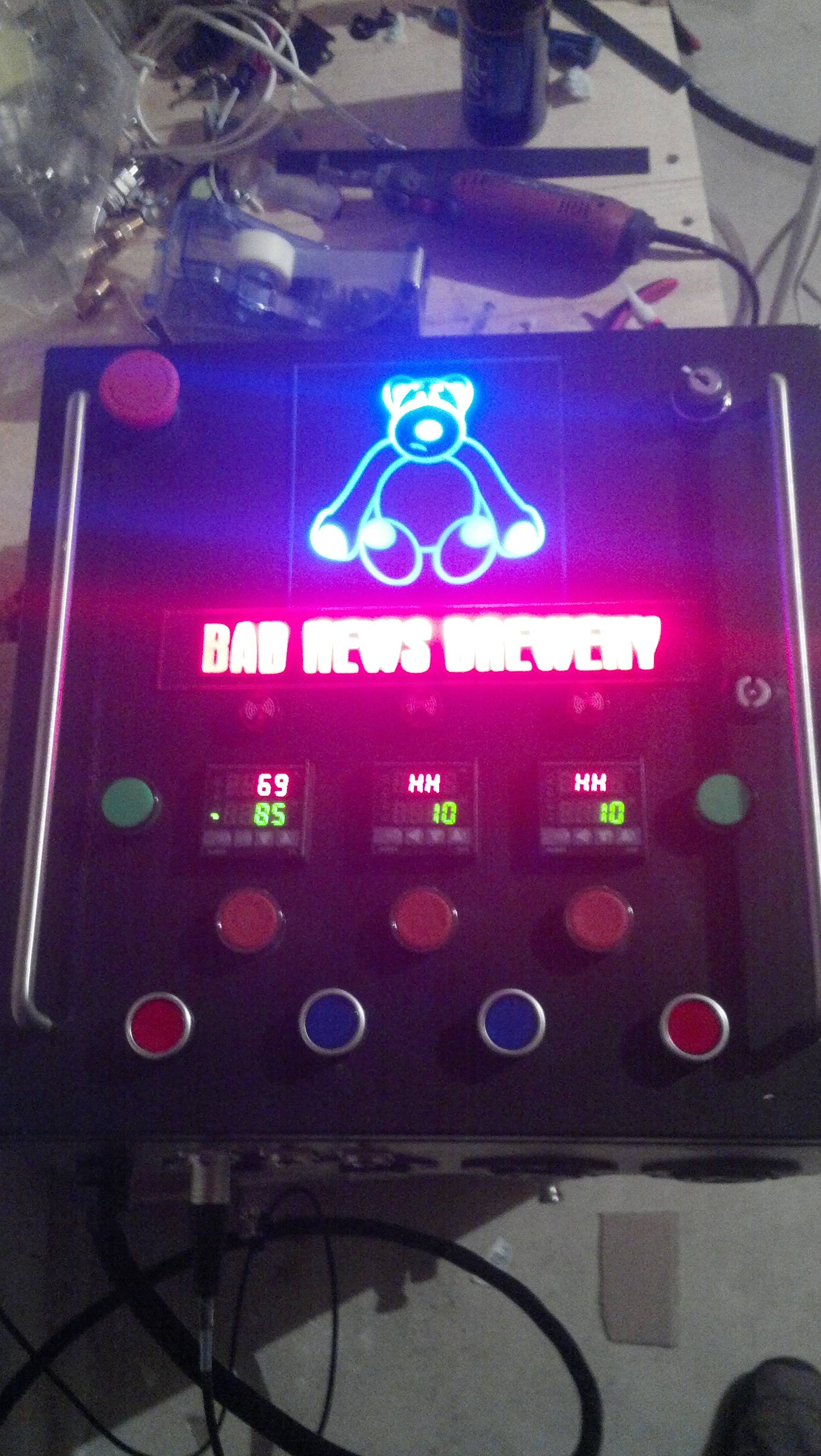
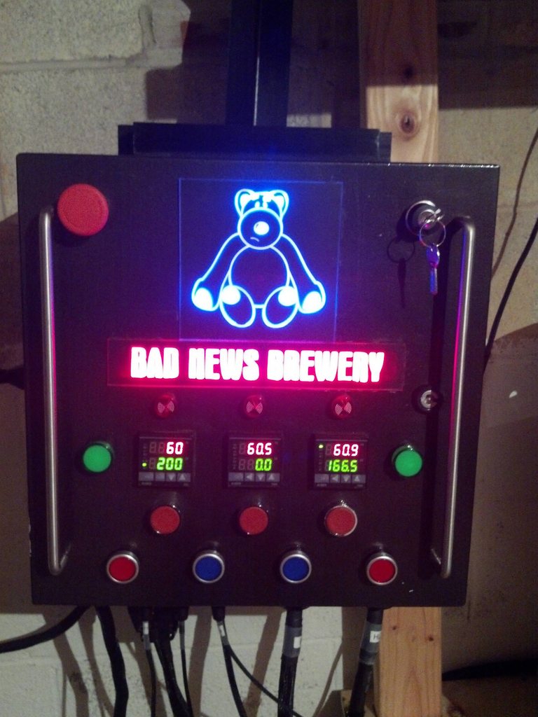
Here is a picture of the panel in its final glory, everything plugged in, powered up and ready to start brewing. None of the bottom switches are on, and nothing's labeled, but here's how it goes:
PIDs (left to right) - Boil Kettle, Mash Tun (temp monitor only), HLT. The green LEDs next to the BK and HLT PID turn on when the PID has the element fired, so they pulse during the brew day. Not a critical component, but a nice to have.

Red switches below the PIDS - they are momentary switches interfaced with the alarm circuit. The PID to the left is a 2352, the so if the alarm buzzer starts to go off, I can depress the switch to break connection (and shut up the buzzer) while I adjust the alarm condition within the PID. Basically just lets me silence the alarm. The other two PIDs are 2451s, which have a timer integrated. The switches were supposed to be part of the timer circuit, to start or reset a timer. I can honestly say I have not yet found the need / desire / time to figure out the timer function of those PIDs, so it was basically a waste to buy them vs. the 2352s, and those two switches do nothing.

The 4 switches across the bottom or LED on/off switches. From left to right - BK element, Pump 1 (Wort), Pump 2 (H2O), and HLT element. Red for heat, blue for water. These switches also have a second terminal block across the back for the safe-start interlock. All 4 switches have to be off before the panel will turn on.

ugGP2Ckh.jpg


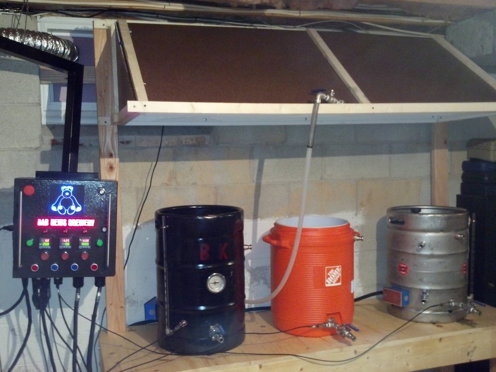
And here is everything set up. I made a quick and dirty hood with some laminate and 2x2s. I use an old, big ass 120v computer fan as the exhaust fan. It doesn't put out nearly enough CFM compared to some of the other fans, but for the cost of $0 and the quick mount up, I'm happy.

The hose sitting on the hood comes from the filter, and is my H2O fill line.

6H2Z4aYh.jpg


So that's pretty much everything. Works like a champ. When I do everything right I'm getting mash efficencies above 90% (according to BeerSmith 2.0) and overall efficencies in the mid to high 80s. Most importantly, it turns water and grain into drinkable beer (with the help of some yeast) and for that I am happy.

-Kevin
 
Right on! I am brewing 10 of a robust porter this weekend... AND I will be testing out my 60L Speidel fermenter for the first time...
 
Right on! I am brewing 10 of a robust porter this weekend... AND I will be testing out my 60L Speidel fermenter for the first time...

not to hijack your thread badnews, and i'm sure you'll let us know in your thread highland, but i'm very curious about that fermenter. let us know how it goes.
 
Ok BadNews, I've been following you around and have finally decided I want to build a control box just like yours. I was wondering if you'd be willing to post a parts list as I know I'll be buying this in pieces and would like a list so I could check off as I went. I don't need the LED for the backlit logo (awesome look, but the name of the brewery keeps changing) but other than that I want to build your box :)
 
Hopefully this works - https://docs.google.com/spreadsheet/ccc?key=0AkaCmiOFtVbDdE91MDc3bElUZnZmUldsNlpnWEtmRkE&usp=sharing

Good luck to you! I've got a lot of left over parts, so if you see something on there listed as excess, PM me and we'll work something out.

Also, I should note that I'm not so sure I would have used the PIDs with timers built in, or put in the alarm silence switches if I were to do it again. I've never taken the time to learn how to program the timer, and frankly it's never been an issue. As such, I've never needed the reset buttons to start / rest the timer. The only reset button I use is for the BK, and I hold it in to shut off the buzzer while I change the PID parameters so it turns off the alarm.

-Kevin

So you're suggesting scrapping those? I had thought about that already as I have a little handheld timer I use already. It should be plenty for me and then I can shut off the burners manually. I like the idea of taking one more thing out of the equation because it means one less thing likely to fail!! :)
 
Is there anyway I can get a full size of your wiring diagram or do you know if P-J is still sticking his head in over here?
 
Back
Top