BadNewsBrewery
Well-Known Member
This is the control panel and electronics sub-build of my overall thread, available here
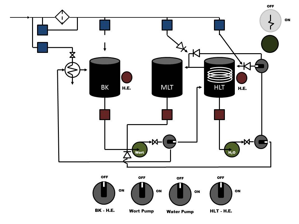
I had originally dreamed of a hard-piped system with all kinds of electronically actuated valves that were controlled by switches on the panel, and each switch would illuminate a pathway on the panel visually showing where the water / wort was flowing – but then cost got the best of me and I realized that the 12 or so valves I would need would have to wait, so I’ll be turning valves by hand. I can try and attach my original schematic for my manual setup in case anyone is curious – it's a highly interactive and animated PowerPoint - you run the power point, and click on the key to ‘turn the system on’ – from there, click on the various colored squares or dials (switches) and it should perform as I dreamed, within the limitations of PowerPoint. I just don't have the web-sense to know where to upload it to make it accessible. Here's a picture though...
So now, a much simpler panel, and manual controls. Thus far I have:
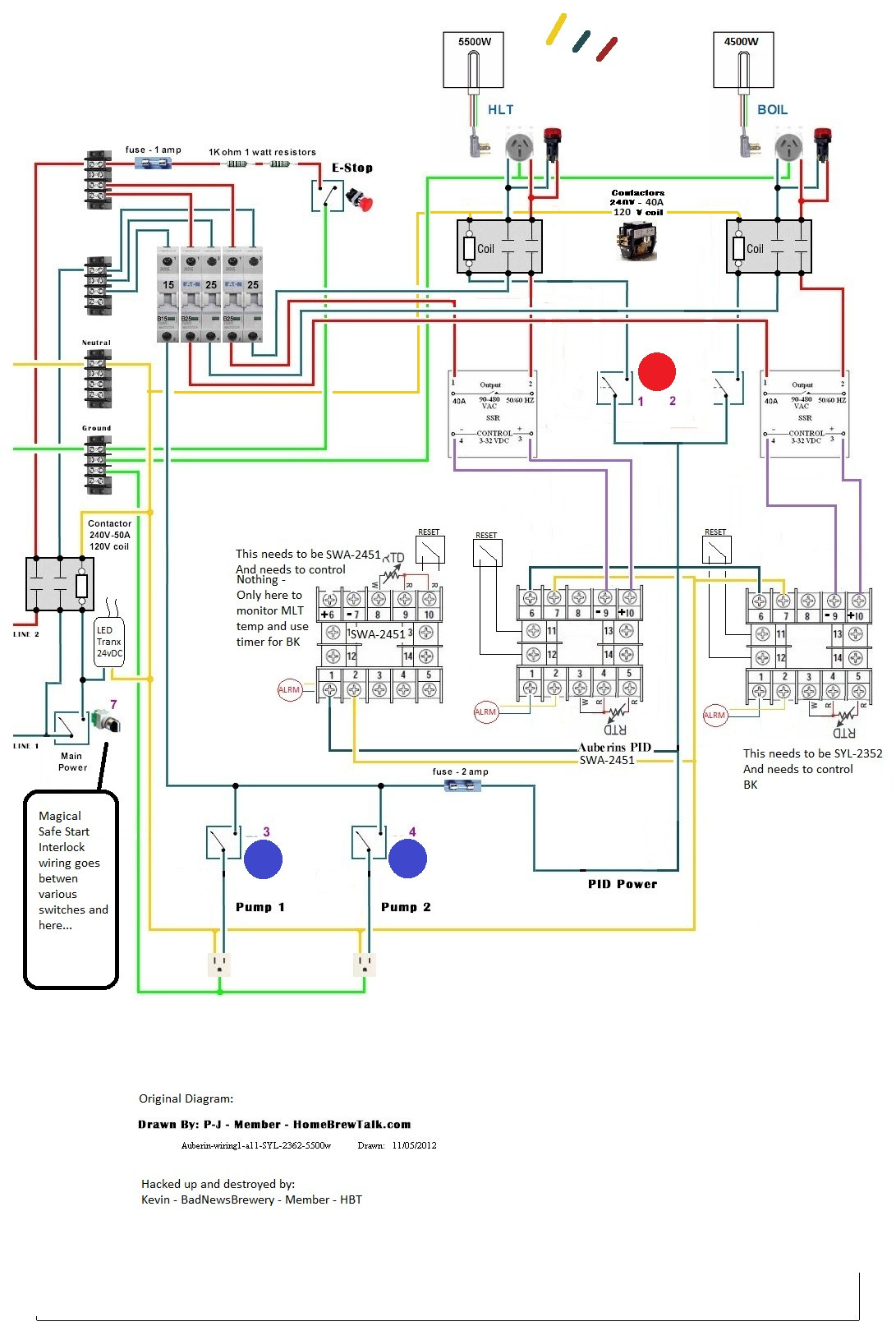
60a breaker in the main panel running a short jump via 6ga wire to a 50a GFCI spa panel that has a sufficiently rated 4 prong receptacle end. This has been installed and best I can tell is working as designed. From there, 6ga runs to the 16 x 16 x 8 panel.
Power will be controlled by a 3 Pole 50A contactor with the coil getting power from a keyed switch. Distribution of power will be through DIN mounted distribution and terminal blocks. I will use3 PIDs - two of the SWA-2451 (one for the HLT, one to simply monitor the MLT and use the timer – no action) and one SYL-2352 controlling the BK. I didn’t use a SWA-2451 on the BK because you can’t use the timer and manual mode at the same time so it didn’t make sense.
The PIDs will control two no-name 40A SSRs from eBay mounted to a large heat sink from Auber. Illuminated push-buttons will close the coils on two DIN mountable 30A Allen-Bradley contacts before the power hits the receptacles. A 4500w element is in the BK and a 5500w in the HLT. With this setup, I should be able to run back-to-back batches, or pre-heat water in the BK and MLT at the same time which should cut down my overall time brewing a single batch. The two PIDs controlling temperature will have associated LEDs to indicate when the elements are firing.
I will be installing an e-stop with the technique P-J uses, and I’d like to incorporate a safe-start interlock like Kal uses – I ordered the 8 pin 2 pole relay and base from Mouser.com Each PID will have its own alarm (16mm light / buzzer from Auber) and its own reset button. I did it this way as I may have one PID monitoring time while another monitors temperature, and it’d be good to get a separate alarm for each.
I have ordered DIN mount rails, along with terminal blocks and distribution points, terminal block separators and end caps, and DIN breakers – two 25a double pole, two 16a single pole – mostly from eBrewsupply.com or Mouser.com
I have various chassis mount XLR connectors and electrical receptacles, all twist lock. The RTD probes will come through the XLRs and the pumps / heating elements will be through the twist-locks. I bought way more XLRs than needed thinking that I’d use the XLR fittings for the electronic valves, if / when I get to that… or I’ll post them for sale.
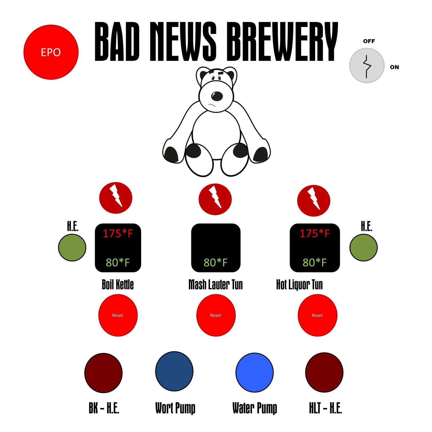
For the power on – I am using a keyed switch from ebrewsupply. In place of the typical LED that most people use to show power on, I want to go a little different. I have a logo designed for my brewery that I’ve been using. I plan to get the logo reverse-engraved in a piece of acrylic from Big Blue Saw and build an LED light box behind it – when you turn on the panel, the logo lights up – if it works the way I hope, it’ll be pretty cool looking. I may just get the logo negative-cut from vinyl and stick it to the back of a piece of plexiglass, or come up with some other idea… I have an LED transformer from SuperBrightLEDs.com and a length of LED tape from them as well. The transformer will take between 85 and 260vac input and give 12vdc output.
Below is a visual interface of how I think the final panel will look.
I would greatly appreciate any advice or thoughts on the process, help with wiring diagrams, ideas on where to get the logo panel done, anything along those lines. The more I trouble shoot this before construction, the less chance of letting out the magic black smoke.
I plan to mount the panel via a home-built ceiling mounted ‘jib arm crane’ that will allow me to adjust the panel to pretty much anywhere within a decent size area, as long as my cables are long enough. I will be writing a full article on this if it actually works out.
-Kevin
I had originally dreamed of a hard-piped system with all kinds of electronically actuated valves that were controlled by switches on the panel, and each switch would illuminate a pathway on the panel visually showing where the water / wort was flowing – but then cost got the best of me and I realized that the 12 or so valves I would need would have to wait, so I’ll be turning valves by hand. I can try and attach my original schematic for my manual setup in case anyone is curious – it's a highly interactive and animated PowerPoint - you run the power point, and click on the key to ‘turn the system on’ – from there, click on the various colored squares or dials (switches) and it should perform as I dreamed, within the limitations of PowerPoint. I just don't have the web-sense to know where to upload it to make it accessible.
Here's a picture though...
So now, a much simpler panel, and manual controls. Thus far I have:
60a breaker in the main panel running a short jump via 6ga wire to a 50a GFCI spa panel that has a sufficiently rated 4 prong receptacle end. This has been installed and best I can tell is working as designed. From there, 6ga runs to the 16 x 16 x 8 panel.
Power will be controlled by a 3 Pole 50A contactor with the coil getting power from a keyed switch. Distribution of power will be through DIN mounted distribution and terminal blocks. I will use3 PIDs - two of the SWA-2451 (one for the HLT, one to simply monitor the MLT and use the timer – no action) and one SYL-2352 controlling the BK. I didn’t use a SWA-2451 on the BK because you can’t use the timer and manual mode at the same time so it didn’t make sense.
The PIDs will control two no-name 40A SSRs from eBay mounted to a large heat sink from Auber. Illuminated push-buttons will close the coils on two DIN mountable 30A Allen-Bradley contacts before the power hits the receptacles. A 4500w element is in the BK and a 5500w in the HLT. With this setup, I should be able to run back-to-back batches, or pre-heat water in the BK and MLT at the same time which should cut down my overall time brewing a single batch. The two PIDs controlling temperature will have associated LEDs to indicate when the elements are firing.
I will be installing an e-stop with the technique P-J uses, and I’d like to incorporate a safe-start interlock like Kal uses – I ordered the 8 pin 2 pole relay and base from Mouser.com Each PID will have its own alarm (16mm light / buzzer from Auber) and its own reset button. I did it this way as I may have one PID monitoring time while another monitors temperature, and it’d be good to get a separate alarm for each.
I have ordered DIN mount rails, along with terminal blocks and distribution points, terminal block separators and end caps, and DIN breakers – two 25a double pole, two 16a single pole – mostly from eBrewsupply.com or Mouser.com
I have various chassis mount XLR connectors and electrical receptacles, all twist lock. The RTD probes will come through the XLRs and the pumps / heating elements will be through the twist-locks. I bought way more XLRs than needed thinking that I’d use the XLR fittings for the electronic valves, if / when I get to that… or I’ll post them for sale.
For the power on – I am using a keyed switch from ebrewsupply. In place of the typical LED that most people use to show power on, I want to go a little different. I have a logo designed for my brewery that I’ve been using. I plan to get the logo reverse-engraved in a piece of acrylic from Big Blue Saw and build an LED light box behind it – when you turn on the panel, the logo lights up – if it works the way I hope, it’ll be pretty cool looking. I may just get the logo negative-cut from vinyl and stick it to the back of a piece of plexiglass, or come up with some other idea… I have an LED transformer from SuperBrightLEDs.com and a length of LED tape from them as well. The transformer will take between 85 and 260vac input and give 12vdc output.
Below is a visual interface of how I think the final panel will look.
I would greatly appreciate any advice or thoughts on the process, help with wiring diagrams, ideas on where to get the logo panel done, anything along those lines. The more I trouble shoot this before construction, the less chance of letting out the magic black smoke.
I plan to mount the panel via a home-built ceiling mounted ‘jib arm crane’ that will allow me to adjust the panel to pretty much anywhere within a decent size area, as long as my cables are long enough. I will be writing a full article on this if it actually works out.
-Kevin