Automated HERMS system

Homebrew Talk - Beer, Wine, Mead, & Cider Brewing Discussion Forum

Help Support Homebrew Talk - Beer, Wine, Mead, & Cider Brewing Discussion Forum:

This site may earn a commission from merchant affiliate links, including eBay, Amazon, and others.
Silly question if this has already been addressed or is implicit in the design, but how do you know you've reached your intended mash volume if you're mashing with the grain already in there? Are you looking at how much water goes missing from the HLT?

I have a question along the same line as this that I figured I would ask here because I am constantly amazed by the knowledge on this site. Ok enough sucking up on to the question.

I have been wondering if there are any digital scales that would work for this? I think this would be the best way to calculate volume of water in a vessel I just don't know if there are any products out there capable of this, especially with a digital read out that would communicate with the brewing controls. I know there are for larger scale item such as truck weighing etc but is there any products that would fill this need in the brewing world?
 
I have been wondering if there are any digital scales that would work for this? I think this would be the best way to calculate volume of water in a vessel I just don't know if there are any products out there capable of this, especially with a digital read out that would communicate with the brewing controls.

Checkout the brewtroller forums about how to calculate volume. The following thread is great.

http://www.brewtroller.com/forum/showthread.php?t=538


Blackheart,

This is great. Haven't been around the boards much due to taking a new job a few months back, but I always watch the updates to this thread. This project is great and you should be extremely proud of this system.

Can you give a little insight into those "special valves" your using to release the air from the system and how they work? Do you have to manually prime the system prior to letting the automation do its thing?
 
It is nice to see it finally coming together and functioning like you intended, nay sayers aside, the automation makes a brew day much easier if you do not have to stand, tweak, and watch thermometers all day. I am looking forward to seeing the system in action with a controller in charge when you get to that point, if you need formulas for level sensor correction let me know and I will share what I use.
 
The "special valve" we are using to bleed air from the lines before hitting the pump is this one from Grainger.
http://www.grainger.com/Grainger/ww...uery=3EJF8&op=search&Ntt=3EJF8&N=0&sst=subset
A few others on here have used the same one. Unfortunately it is brass, yet seems to be the only solution anyone has come up with to bleed air automatically. Still deciding if we need an additional one on the outlet side of the pumps as well. Once you get past the dip tube line the flow drops off from the pumps and has more air on the outlet side of the pump.

Thanks for the link to the thread on pressure sensing. I havent seen how brewtroller does it, but we are doing it with a pressure sensor that will be mounted on future sight glasses. Waiting for our sight glasses to come in first. It is a Differential pressure sensor, so it has one probe in an one exposed to the air. This should be easier to calibrate and compair even if things get messed up a little. We will see though. Going to have to do some experimentation first.
 
Will the pressure sensor be a wet model or are you going to work with trapped air in sight glass. The formulas I have use temperature and calculated SG to correct for liquid density changes as mashing and boiling process are running. If you have not purchased the differential sensors there are some 0 - 2 PSI wet pressure transmitters that have voltage outputs for about $120 each out there.
 
Will the pressure sensor be a wet model or are you going to work with trapped air in sight glass. The formulas I have use temperature and calculated SG to correct for liquid density changes as mashing and boiling process are running. If you have not purchased the differential sensors there are some 0 - 2 PSI wet pressure transmitters that have voltage outputs for about $120 each out there.

We are using one of these.... http://www.futureelectronics.com/en...artNumberSearch|MPX5100DP|1|,Ny:True,Nea:True

a differential pressure sensor. One barb will be connected to the sigh glass measuring air pressure inside the sight glass, which will be sufficiently tall as needed to not allow liquid to enter the sensor.

The other barb will remain open to the air. The sensor sends the pressure readings of both ports and then its a simple calculation to figure out the pressure in the sight glass. Then using some simple calibration we should be able to fairly accurately measure volume.

We have hit one snag during further testing. We scorched and melted two of the 10 solonid valve wires as the frame heated up to over 400F So now we are looking at ways we can cover the wires so that they are heat resistant without melting the wires inside. The first thought that popped into my head was to use 1/4" silicon tubing. This would allow the outside to resist heat and keep the wires inside from melting as well. If anyone has a better idea please let us know!!
 
Here is the wet sensor I was mentioning http://www.meas-spec.com/downloads/LM_Series.pdf, this would work in a wet remote mount setup. with the wet setup you do not need air pumps for bubble tube or sealed tube in kettle for dry pressure sensors. These can be found at Mouser for about $114 each, and I have seen them on ebay for less than half that, they were used in the RV business as tank level sensors and there has been liquidation of some inventories of parts.
 
Those seem like nice sensors. At this point they may have to be an upgrade. We picked up 3 of the air pressure sensors for $60 total. Still working out the sight glass/pressure sensor configuration that works best for us. We will definitely be keeping those in mind.
 
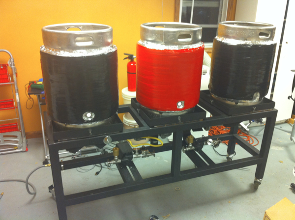
After brewing for the first time this Saturday on our brew system we are happy to report success! Their were a number of issues we ran into but lets talk about what went right first.

One of the most surprising things was that the burners worked so well. They heated ~5 gal in the kettle and ~10 gal in the HLT fairly quickly. The keggles also maintained temperature very well during mashing. We simply fired the burner under the HLT and kept recirculating using one of the pumps to maintain mash temp indirectly. Computer automatin will really help things here.

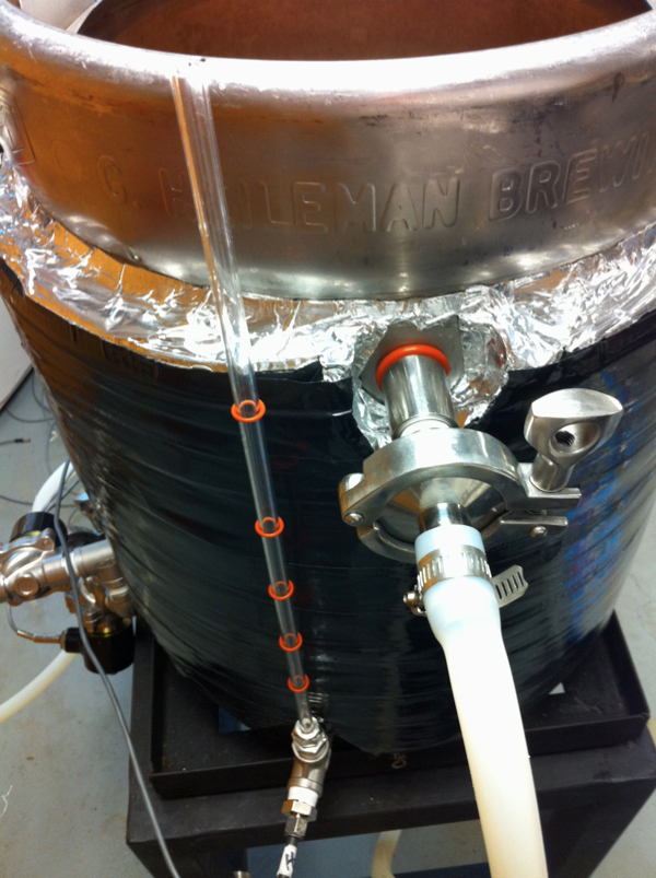
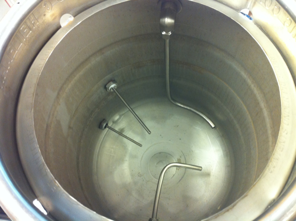
We used a spare piece of 1/2" silicon tubing that we pushed inside a 1/2" coupler to use as a sparge arm. We are awaiting a special 1/2" MPT to barbed adaptor to better couple the tubing to the coupler but just pushing it inside the female threads worked fine for this batch.

The most important part though was that we were able to extract sugars from the grain! This was not only our first time brewing on our new system but also our first time brewing with all grain!

Now onto the bad news... what went wrong...

Throughout most of the brewing process our system uses 1 pump, with the excepting of some dual recirculation, and most importantly, sparge out where we go A->B->C at the same time. It was right before this critical use of both pumps that one of the SSR's decided to fail and we had to manually plug/unplug the pump in order to control sparging flow. This is making me seriously consider segway style dual redundancy for everything...

We have 10x 12vDC 1/2" solonid valves in our system. Some of them get super hot, while others do not. One got so hot we had to stop using it, it was on for less than 5 minutes. No shorts or other wiring issues were found. Strange, but we need to look into why some are almost 200F while others are cool, with no liquids inside.

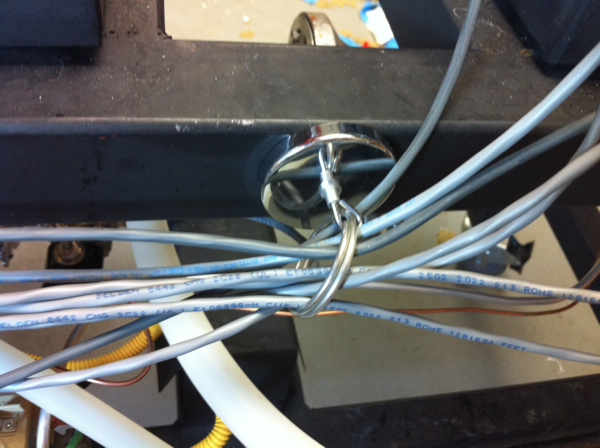
Wires for the solonid valves were another issue, we hand made cables with a mono 1/8" headphone jack on one side and a barrel power plug on the other. This was so that the cable could carry the necessary current to power the valves without melting, as audio cable is not rated for this kind of thing. We neglected to take into account how hot the frame would get and we melted two of the wires. We definitely need to both protect and better route the wires.

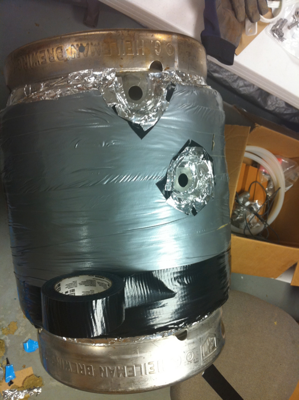
Our temperature probes were useless in some cases. We were brewing a 5 gal batch instead of 10 for our first test batch. This means that the temp probes placed at the half way point on the kegs were useless when they were 1/3 full with 5 gal. It looks like we will be getting sight glasses with temp probe slots and adding additional probes to all 3 kegs.

We definitely over sparged. Our initial brix reading was 5, and we were shooting for 13.5. So not sure if it was purly over sparging (due to pump issues etc) sparge rate of flow was too fast, too much additional sparge water from the HLT, etc but we had to add ~3LB of DME to bring up the reading to 15 which then settled out at 14.5 when we finished the boil.

All in all it was going really well considering a few minor technical glitches and in experience, we had 5 gal of wort in the kettle and were boiling away. Just when we thought we were home free, disaster struck.

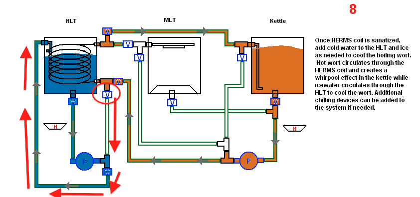
We were in the whirpool stage of our brewing where we recirculate the boiling wort through the HERMS coil while nothing is in the HLT and then add ice and water, and recirculate that at the same time to cool the wort. We had just tightened everything down in the coil previously so their would be no cross contamination. Their was a bit of left over wort in the pump lines in the HLT from a previous step, which didnt matter as it was recirculating over the ice and not the wort. So when we saw some foam and beer colored water enter the HLT return we didnt think anything of it, it was coming out COLD.

When we removed the lid on the kettle and saw a few gallons missing, and opened the HLT lid and saw a huge mound of foam, we knew something was wrong. At that point we shut everything down and dumped what we had in the kettle into our 3gal kettle and brought it inside to cool it in the sink as we have done for the past 4 years. We were able to save about 3 gallons of the wort, but lost about 2 into the HLT. After cleaning and testing again we figured out what was going wrong.

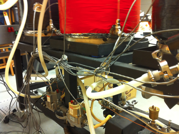
The red arrows in the picture show the path of *some* of the wort during cooling. It would appear that the indicated valve that was OFF let *some* of the wort through it, mixing with the 35F water causing cold, mostly water, wort to enter the HLT.
hermsfail.png


All of the valves are one way as indicated by a -> on one side. We had a few problems with other valves that were put in backwards and they weren't flowing. In this case the valve is in the correct way. During testing afterwards, we put 5 gal into the kettle and recirculated through the HLT coil with nothing in the HLT. The pressure was enough that it was entering the distribution section connected to the outlet of pump 1 and the path of least resistance was to enter the HLT return. Clearly we have a defective valve or we need to reconfigure something. We may be able to fix this simply by swapping this valves location with another valve, like the one in front of the HLT.

So now, our 3 gallons of beer is happily fermenting away in its new fermentation chamber. We are very happy our system worked overall and we were able to produce beer with it. Though their are a few problems with the system at the moment, we believe we can fix all of them and be ready for the next batch.

If anyone has some suggestions or questions on what we did or what we are going to do in the future let us know. Also, the entire session was filmed on a 7D so after that is edited it will be up here.
 
Here are a couple solutions to the pressure differential problem, minimal change is to put ball valve in HLT recirculation line to create enough back pressure to keep solenoid valve closed while HLT recirculation pump is running. Better solution is to move HLT recirculation pump sparge solenoid from coil inlet to after the solenoid valves that feed MLT sparge line(replace tee with cross), this minimizes reverse pressure difference. If you are interested I think I have a design sketched up on paper that will do what you are trying to do with only 8 solenoid valves. The solenoid valves that had gotten hot are probably not fully opening, the moving armature inside is not pulled up against the internal stop and the coil is drawing a lot more power trying to get it into position. This is why we put a bolt or screwdriver through the coil if we have to lift one while it is energized, otherwise it will burn up.
 
I talked to http://www.dudadiesel.com/ where we got the valves. He says that this temp is within the normal range and that during operation with liquids flowing through it the temp will drop. Also, some leakage will occur due to the type of valve in the reverse flow. We ordered 2 SS check valves, which were a bit difficult to find in 1/2" SS for less than $50. This should solve the problem. We may need more in other areas if similar problems occur.

We also ordered 3x sight glasses from weldlessfittings.com with 1/2" T connectors. We then ordered 3x more temp sensor probes and 1/2" brushings from BrewersHardware.com so we can get more accurate readings at the 5gal level and average temps between the two sensors in the same vessel.

Waiting now to place an order to McMaster. Want to get something to wrap the kegs in. Looking at mineral wool that comes 1-2" thick. Looks like it could work well but not sure how to cover it on the outside of the keg. Metal tape maybe? not sure but it is cheap, warm, and high heat.

Other issue we are running into is with the heat resistant wires. Looking at 1/4" fiberglass sleeving. Again, high temp, this stuff should do the job. Now we just have to figure out how to route the wires. Something with magnets could be cool. Also looked at SS hooks/eye loops that screw into the frame to route the wires in. Everything else cant handle the 200F+ heat in some areas of the frame.

Anyone have any ideas about the keg insulation or wire management?
 
Hotsy has some nice insulating material. They wrap the heat coil with it and the paint on the outside don't burn off. Reasonably priced and you can buy it by the foot.

Can you tell me more about what material you are talking about or a link to it?
 
It is the insulating blanket they place between the coil and the outside of their hot water pressure washers. It is a nice white blanket type material that is easy to wrap around the coil and does a very good insulating job. I did a quick search but didn't take time to sift through. If you have a Hotsy dealer in the area they will have it on hand. Seems to me it was 3/4 to 1 inch thick.
 
The material you are looking for is Kao Wool, a 1" blanket should do quite well, look for the "Adobe" finish aluminum pipe insulation wrap to cover the keg insulation.
 
Just put in the order for McMaster.


Nuclear Grade Duct Tape 2" Wide X 60 Yards Long, Silver $17.83

10 Magnet-Mount Wall Hook 2" Dia Plate, 1-1/32" Proj, 20 lb Hold Power $45.40

50'x 1000 Degree Fahrenheit Fiberglass Sleeving 5/16" ID, 9/32" to 11/32" Bundle $18.50

15x 18-8 Stainless Steel Clevis Pin W/Hairpin Cotter Pin, 5/16" Diameter, 1" $22.95

1x 316 Stainless Steel Split Ring 1.605" OD, 1.395" ID, .21" Thick, Packs of 10
$10.92

4x Mineral Wool Insulation Plain Faced, 1" Thick, 24" X 48" Sheet
$24.76

Total $140.36

That should handle the insulation of the kegs and wires. Going to use the 2" magnets to hold split rings to the frame of the brew system. Then put the fiberglass bradding on all of the wires and run them through the split rings supporting them.
 
blackheart,

I build my system based off your flow sequences. I started fluid testing a few weeks back and noted the same problem, and a couple others.

I spent about a week trying to figure exactly where water was flowing and when, as I encountered a fair amount of "reverse flow leakage" that you mention.

Specifically, I noticed:

1. During recirculation, I had wort entering the HLT fill.
2. I had some flow into the HLT DRAIN during the sterilize.


There were a couple other small issues that I noticed, but I will need to go through my notes to clarify. I took a break from the system for a couple weeks while working on a different project, and am about to get back to the brewery.

If you want to PM me, or discuss here, I am more than willing to help.

Bryan

Any experience you have with this would be very helpful. Trying to get everything up and running again this weekend and do more extensive testing next week. Then, brew another 5 gal batch next weekend.
 
Blackheart,

I'll dig up those results for you later this eveing when I get out of work...

Where are you planning on putting the check valve and do you know the cracking pressure and flow restriction?

Thanks,

Bryan
 
It didnt list the cracking pressure and flow restriction but we will give it a go. If it doesnt work we may try to swing check valve instead from the same company.

On another note...
I think we may have come up with a name for the brew system.....

hermes.png
 
I bought some swing valves and will le you know how it goes. All my coding and wiring is done on my system. Just gotta test this weekend.

Gotta go do the bender!

Wow you are a bit ahead of us... the entire build we are considering a "beta" version if you will. We are hoping to figure out all the bugs in the system so we can build multiple copies and brew a few batches at the same time with less people as they will be mostly automated.

Have any pictures of your setup? What are you using to control everything?
 
My build is for personal use so it's always beta :) I am very happy with it though. Im using a Fez Cobra (domino would work as well). It's a .net mf 4.1 c# device. I have all the services,devices and util classes defined and running in appropriate thread. I also have a SOAP service on it so I can hook into it with fancy GUIs like .NET or a WCF proxy for WPF/Silverlight. I have some pictures and will post some this weekend. Maybe a video or two. I was just about done tuning my level system (bubbler type from brewtroller) and got bit with the back flow issue with the solenoids. I did go all electric though which is different from your build. I plan to eventually post my code for others to use if they want. I want to finish the fancy UI piece first which might change the SOAP (DPWS) web service. The build has been going on for so long I remember the other night I actually will be making beer soon. Very nice!

My site has some notes.
http://www.BakkerBeerHouse.com
 
I have 3 extra solenoids which I might be able to fit in (back to back of another) to be able to fix the back flow issue. I found the BK, HLT and the HERMS line to have issues. 3 should do it. I havent extensivly tested though so there might be more. I did have an issue with my march pump lines having too much air in the line. I would figure all the water weight would flush them out but the leaks could be getting me. Ill post this weekend.
 
Hey Guys,

So, going over my notes, here are some of the issues I encountered.

1. During Dough-In, I had some unwanted fluid flow into the HX output.

2. During recirculate, I could not cycle water through the HLT. If I did, I would get a small amount of wort mixing into the HLT fill. I eliminated this by installing an electric ball valve at the HLT fill line and eliminating recirculation of the HLT water upon itslef.

3. During sparge, wort flowing from the HLT would flow to BOTH the MT and the kettle. As I restricted flow TO the MT, I noted increased leakage into the kettle. The result was hot sparge water diluting the wort in the kettle.

4. During sterilize and chill (which no longer has the loop recirculation of the HLT for reasons stated above) I would have wort entering INTO the HLT drain. This was cured by adding the electric ball valve to the HLT drain port to prevent reverse flow. This was the biggest *****, because now I could not effectively chill the wort. The fix to this was the addition of another HX in the kettle that will have tap water flowing through it during chill. Think of it as a permanent immersion chiller mounted in the kettle.

I'm about to wrap up the new HX in the kettle and then resume testing. I'm hoping that these fixes bring the system up to operational. TBD but optimistic!
 
Guys,

I also had problems with air and priming. I too thought that gravity would force water/wort into the pumps and push out all air. Not so lucky. I have been able to eliminate the problem with a couple switches on and off of the pump while opening and closing the valves. I have manual/auto switches that allow me to do so. I would imagine you could write in code to turn on and off the pump a few time before keeping it on to flush out any air in the lines...

Blackheart, have you tried the air bleed valves yet, and if so how do they work?
 
Thanks for the notes bkloos. We received all of our new parts yesterday night from McMaster and weldless fittings. Going to strip down the whole system, add sight glasses, insulation, re assemble, test etc.

The new one way valves are not yet here but should be by next weekend when we plan on brewing.

We are using the air line bleeders and they were working OK in testing, I think they may just needed to be broken in because when we were actually brewing we had zero issues with them. At worst it took a pump a few seconds to get going full power with no help from us.

This is the first brew system we have designed and the first time we have done all grain brewing. I expected things like this would happen. Because everything is modular we can quickly revise the system, add additional valves etc and try again. Going to do much more testing this time.

If you guys find out any more info or fix any more issues with your systems please let us know. We will continue posting our ongoing progress here as we update our system.
 
The "special valve" we are using to bleed air from the lines before hitting the pump is this one from Grainger.
http://www.grainger.com/Grainger/ww...uery=3EJF8&op=search&Ntt=3EJF8&N=0&sst=subset
A few others on here have used the same one. Unfortunately it is brass, yet seems to be the only solution anyone has come up with to bleed air automatically. Still deciding if we need an additional one on the outlet side of the pumps as well. Once you get past the dip tube line the flow drops off from the pumps and has more air on the outlet side of the pump.


Is this installed in a Tee at the inlet of your pump?
 
Blackheart,

Another point would be to rotate your pumps 90 deg so that they fill from the bottom and pump up. In this configuration, gravity pushes fluid into and through the impeller housing, and the bubbles float up and out of the pump.

This may help some with the priming....

Bryan
 
We have been working on the brew system more this week. Thought I would share some of the updates to the system.

Here is the system after we added insulation to the kettles!

s32.jpg


We used some cheap heat resistant wool from McMaster(posted earlier I believe) at $8 a keg, it was a good deal. Only problem was that stuff was more of a compressed board then a soft wool blanket. When we bent it around the keg it would start to fall apart. Hence, their is no pictures of the wool itself as all of us needed to help with taping the wool on.

The tape does not stick to the wool, it really just sticks to itself and binds the wool to the keg with pressure of the wrapping of the tape. We would get 1-3 wraps at various points then wrap the entire keg. After that we used some water proof aluminum tape to finish off the tops and bottoms as well as around all of the holes.

s33.jpg


The final layer of tape was a cheaper grade colored tape to make it look nice.

Also shown in these pictures is the T with the air bubble valve. Also, we added cotter pins to the kegs to make them quicker and easier to remove from the tipping stands.

We also installed the sight glasses from Weldless Fittings and inserted our 10" temp sensors from brewers hardware inside them. Still need to be calibrated.
s34.jpg


We also routed all of the wires neatly behind the system using the 2" magnets with hooks and bending over the hook to enclose a SS split ring thats about 1.5" inside. All of the wires will be sleeved in high temp resistant fiberglass sleeving but for now they are doing ok in this test config.
s35.jpg


Here is a close up of the magnet/ring combo. These have plenty of sticking power and we have only use about half of them so far
s36.jpg


Whats left to do before the next brew day (saturday) besides making a starter etc...

- Replace the bad SSR
- Tighten and test all fittings
- Add check valves to system
- Fix two burnt wires
- Sleeve wires
- Crimp RJ-11 connectors on 7 temp sensors
- Wire temp sensors to arduino
- Wire arduino to pump switches
- Write code to control pump speed with arduino
- Calibrate sight glasses

We now have two temp sensors in each kettle, one in the middle (8") and one at the bottom (10") and a 7th one in a Tee connector for the recirculation temp. We only need 3 to work to brew this weekend but we might be able to get all of them up and running. Connecting the pumps to the arduino should be just a simple transistor to protect the I/O pin of the arduino and modifying existing PWM code.

What do you guys think so far?
 
You sure that outer black/red tape isn't going to burn? Mine get really hot down there. Especially over the vents in the skirts.

0304bf0c0b43d66816b7d091c3650395.jpg
 
You sure that outer black/red tape isn't going to burn? Mine get really hot down there. Especially over the vents in the skirts.

0304bf0c0b43d66816b7d091c3650395.jpg

Thats why we added the foil tape. We will see how things go in testing. The tape under it is "nuclear grade" from McMaster..... Not sure what else we could cover the kegs with to protect them? any ideas?
 
Re-routed all of the wires. Patched up the two wires we melted. Reinstalled all of the fittings, including making two return tubes that we havent gotten around to doing. Tried to sleeve all of the cables individually but the fiberglass insulation seems to be made of individual fibers and sheds all over the place and is unusable for brewing. I think with the new wire hanging all of the wires should be out of harms way. They do make cable wraps so we could wrap the entire bundle later.

Eventually going to label everything so it makes everything go quicker. Still have the 7 temp probes to crimp RJ-11 connectors onto. The wires are run and cut to length, and we have 2x 5->1 splitters to plug the sensors into. I thought I had a RJ-11 crimper on my network crimper but I guess not. Going to have to pick one up this week and get the sensors online.

Still trouble shooting an issue with pump 1 not working. The pump is fine but the control circuit is having some issues. The normal operation should be, flip the switch, and 5v gets sent from the switch to the SSR, which then throws open the Hot side of the 120v. The 5v signal passes through a Hub PCB that then routes it to the SSR PCB before it reaches the SSR... The signal going into the SSR board is 5v.... sending 5v directly trips the SSR with no problem... but when using them both together I get a reading of 0.5v on the SSR so it sounds like something funny is going on with one of the boards.

Basically, all we need to do to brew again is to connect the temp probes to the arduino, sort out this SSR issue, connect the pumps to the arduino to control the speed, and test the one-way valves.

We are planning on brewing this weekend so hopefully everything will be fixed early this week and we will have time for testing thurs/friday.

Here is the boil kettle with the whirlpool return.
s37.jpg
 
Back
Top