Automated HERMS system

Homebrew Talk - Beer, Wine, Mead, & Cider Brewing Discussion Forum

Help Support Homebrew Talk - Beer, Wine, Mead, & Cider Brewing Discussion Forum:

This site may earn a commission from merchant affiliate links, including eBay, Amazon, and others.
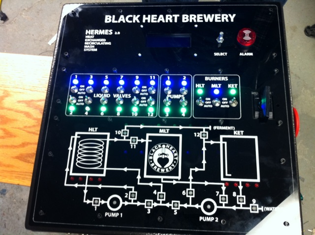
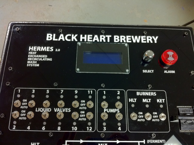
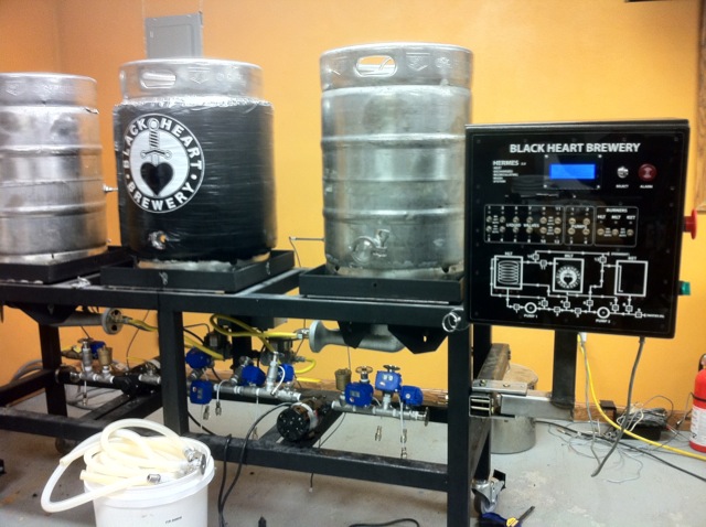
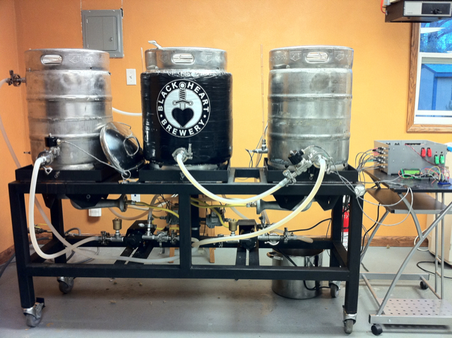
We finally got around to brewing the second test 5 gal batch on the system. The biggest delay was figuring out what to do with the keg insulation to prevent it from burning. We removed the insulation on the HLT and Kettle and left it on the mash tun. Re-taped it with black and added a vinyl logo to it.

s39.jpg


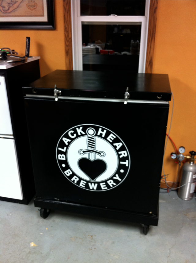
(We also added a 20" vinyl logo to our kegerator)

s38.jpg


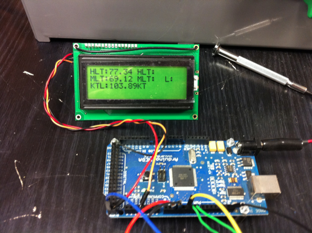
Here is the arduino reading the temp sensors and reporting the temps on the LCD. We only used the bottom 3 temp sensors as they were the only ones touching liquid with 5 gal.

s40.jpg


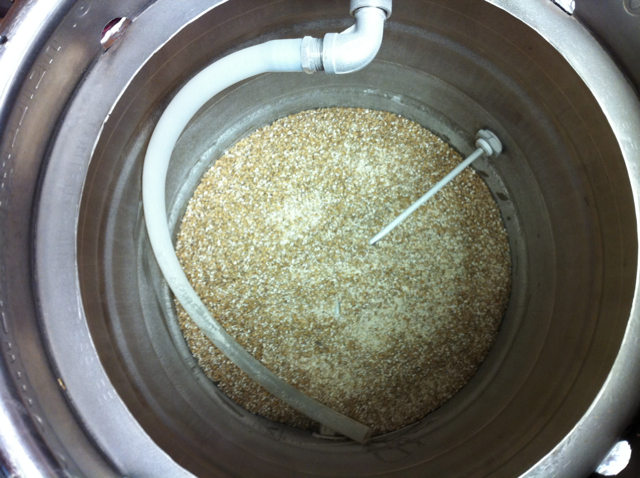
Here are the grains in the MLT with a new 1/2" barb fitting for the silicon tube sparge arm from BrewersHardware.

s41.jpg


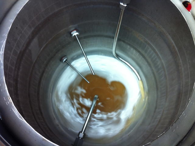
You can see the nice whirlpool effect the curved return tube in the kettle has

s42.jpg


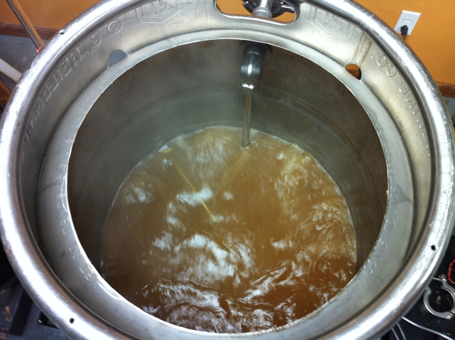
And here we are doing a full 7gal boil.

s43.jpg


So good news is that we were able to successfully extract sugar close to our target gravity. We had no leaks and no reverse flow or mixing issues.

We tried to use PWM control on the arduino micro controller to control pump speed but it was not working and still needs to be messed with more.

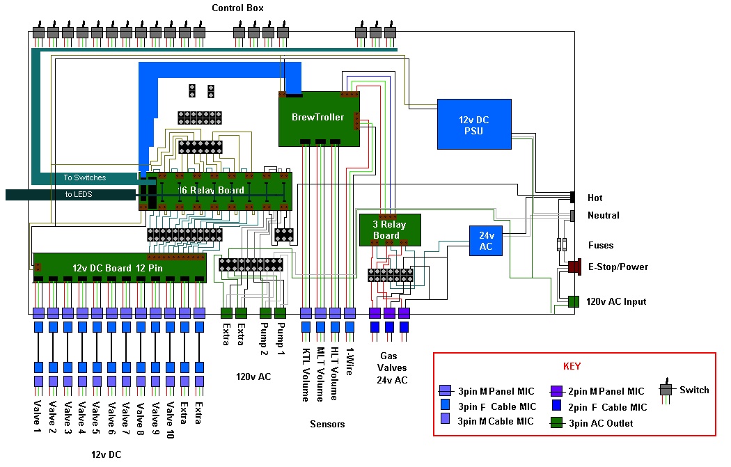
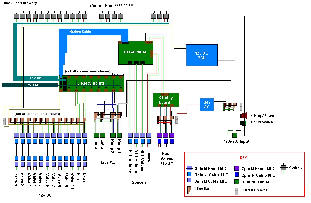
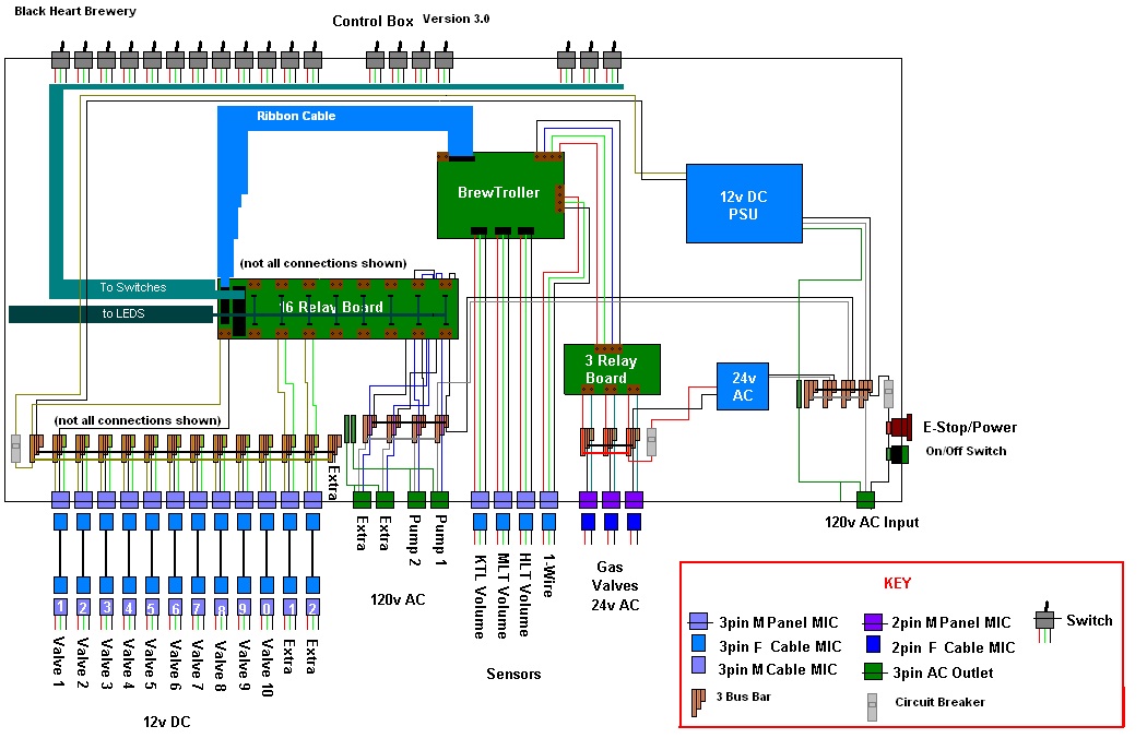
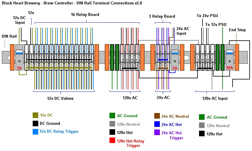
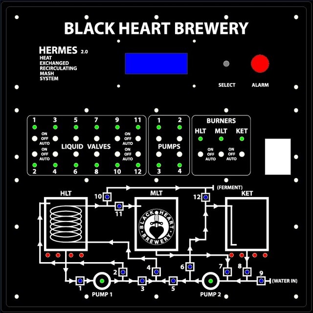
The major problem we did run into however was stuck circulation when pumping. If you look at the flow diagrams you can see that pump 1 never pumps anything other than clean water, its only input source is the HLT. Pump 2 does most of the heavy lifting, recirculating the mash and boiling kettle water. We did some tests prior to brewing and everything worked great with the exception of one valve that would not stay closed, we were able to disassemble and clean it and it works fine now. I'm thinking their must be a blockage in either the 1 way valve we installed or in the coil or other valves as the flow was restricted at times to a trickle coming out of the coil and into both the MLT and kettle. Because of this sparging took forever to get more HLT water into the MLT, though wort from the MLT into the kettle went fine as shown in the pictures above. Hopefully tonight we can take some of the parts apart and try to find the blockage.

I was pretty certain that with 1/2 for everything we would not run into blockage issues like this. Anyone have suggestions for filtering, cleaning, or maintaining our system?
 
Im replacing my duda solenoids for the MLT. It clogs way to easily. Also the BK one that is used for recirculating deformed for some reason so that will probably be replaced as well. Probably with a ball valve type setup. Make sure the bk valves are working right. I had a the same issue with the coil and found one of the BK solenoids were still leaking (in the forward direction). As far as filtering. My MLT false bottom has done a great job for me. I made sure to block any big holes (from grinding) with piece of silicon tubing. After I'm done I use a wet vac to suck everything out and then do a clean up cycle with 150 degree PBW and then a few fresh water rinses.

I made an incredible dubbel so otherwise things are rocking.

We will most likely have to double check all of the valves, thankfully they are easy to take apart. We had false bottoms on all 3 vessels but removed all but the MLT false bottom. The plan was to point the dip tube in the BK down at first to transfer water for mash in then later rotate it upwards to allow for recirculation and whirpooling to not pick up trub. We failed to remember to do that and it was already pumping slowly so by then it was too late.

I saw a few people used a wet vac, we happened to have one and it worked great to suck all of the remainder bits of grain out of the MLT in literally seconds. Also used it to try to suck out the clog in the coil path but only had limited success. Going to have to run some hot water through everything and keep testing individual valves until its all working smoothly again.

Have a nice big jar of PBW, going to definitely use that before the next batch. Should we be checking the pumps as well for debris?
 
I did the same with my false bottoms. My MLT FB has a hole big enough to allow a lot of stuff into the circulation. This did mess up some solenoids (very easy to clean). I took the pumps apart and they were fine. They have nice big openings. After my last batch I took everything apart and only found one grain kernel stuck in the MLT solenoid. One of the reasons I want to replace it.

Wet vacs rock!
 
I have some belimos i use now to regulate my pump flow. they are slow (90 second swing) but I dont care for the MLT. I can wait 90 seconds. They use two relays though which I dont like but its better then nothing. I have an extra one which will go in before we do our boddington clone this weekend. I think that will cover all of my issues with the physical piece of the system. OH yeah. Im going to use marbles at the bottom of my MLT to help with the extra space caused by the MLT. It is 2 inched high which comes out to 2.5 gallons of water below it. Way too much.
 
So we have been looking at a few different possible solutions to our problem. The best solution seems to be to buy 10x new ball valves (~$500) which would require disassembling the entire system and rewiring all 10 valves with new connectors as they are 3 wire not 2 wire like the current valves.

We will most likely keep some of the valves for other stuff like auto pumping water in to the batches. But sell the rest to recover some of the cost of the new valves. We have already modified the valves with handy 1/8" audio jacks making it really easy to throw these into a system.

Also thinking of re-plumbing the entire system so that the majority of the valves are under the brewing system connected in line with hoses extending upward to go into the kettles. Not sure how well this will work, but it will keep more valves away from the burners heat and could help to simplify flow issues as well as allow us to better clean the entire system.

I drew up a quick picture showing this layout... I may have to post this elseware as well but the more feed back we can get the better. Here is the link as the photo does not look good in a small resolution.
Hermes v7

2x one way valves keep liquid coming from the coil from dropping down into the rest of the system.
 
I got them from
midwest BAS http://www.midwestbas.com

Belimo B315+TR24-3-T US $95/ea
No flow problems at all. They are much better then the solenoids. They do take ~95 seconds to swing and need 24vac. A cheap transformer can do that for the 5 valves. It's nice to because they arent powered the whole time so there is no heat to worry about. I found the one I connected between the MLT and BK needed some check valves on each output of the kettles because things could mix when the valve is swinging.
 
One more thing. These valves have the highest flow rating because the cv plate in them is almost nonexistent. You could buy one with a lower CV rating and just pull the disk out. Probably will save u a fee $$.
 
Curtis from midwestBAS.com here, and I just wanted to say, on behalf of all of us, thank you! We had no idea you could use these guys in a "Lazy Automated Brew System". Should you ever need more, or if anyone should come to us from this forum, give me a call directly, I'd be happy to try to come up with a "Beer Brewers" coupon or something.

866/313.2207 -- Just ask for Curtis or Dave and mention homebrewtalk.com
 
I just jizzed in my pants reading this entire thread, job well done fellas.

-=Jason=-
 
Thanks guys, I gave curtis a call and I think we will be able to find the valve/actuators we need. Really cool company as they sell to end users like us, not just people with corp accounts. Also, I hear the owner is a home brewer himself. :)
 
Working on revamping the entire electrical in a real enclosure with fuses/breakers and nice automation type parts etc. as well as BrewTroller automation.

Here are the power requirements for all of the pieces so I can figure out circuit breakers to use etc.

Power Requirements

24V Transformer [10A @ 120v MAX draw]

PSU 12v [3A @ 120v]

12x valves 12v @ 80MA = [960MA @ 12v]

3x Gas Valves 24vac @ 0.5A = [1.5A @ 24v]

4x Pumps 1.4A @ 120v [5.6A @ 120v]

Brew Troller 12v @ [1A @ 12v]

Relays 30ma @ 12v x 19 = [570MA @ 12v]

Total AC Available ?? (must check switch box)
Total AC Drawn 5.6A + 3A + 2A = 10.3A MAX

Total DC Available 3A
Total DC Drawn 2.53A (max)

Total 24v AC Available 10A
Total 24v AC Drawn 1.5A (max)

So it looks like about ~10A max draw with everything on... I assume I use a 10-12A breaker on the AC lines? This is assuming all parts are on and at full draw etc....

Also, should I add breakers to the 12v and the 24v lines to protect the PSU and transformer individually? Should I be fusing each device (pumps etc) individually?

Here is a rough draft of the wiring diagram for the electronics.
connections2.jpg


Trying to spec everything out down the the last wire gauge/color and connector type so we can order everything then just sit down and wire it all up. Also contemplating a custom built box thats pre painted and punched with all of these holes.

Most likely will have to order everything before we decide on a final layout and can roughly lay things out on cardboard. Also, this box will be mounted on most likely a swinging arm on the right side of the brewing system enabling better control and wire management etc. Some pictures of that will be coming soon.

We already ordered 70 MIC connectors for most of the IO of various types. Next order is for the Brew Troller boards etc and the valves, about $700 worth of parts. Hoping to get a jump on this while we have some time off over the holidays.

Right now we could really use help in selecting circuit breakers, E-stop button, 20x switches, and general automation parts like DIN rails, distribution blocks etc.
 
blackheart, I've spoken with my boss and a couple of our engineers, they're more than willing to talk to you about building your panel for you once you have the desire spec ready.
 
as far as fuses you want to add as many as you feel comfortable. A single short taking out everything wont be a good thing. Remember though that most fuses/diodes wont be quyick enough to protect the troller so keep those relays in the middle!
 
blackheart, I've spoken with my boss and a couple of our engineers, they're more than willing to talk to you about building your panel for you once you have the desire spec ready.

Thats awesome! I am specing out the panel now. Ordering parts like fuses and what not, doing a cardboard mock up, and then a digital drawing.

I visited a local coffee roaster (like a nano brewer for coffee) and they have a custom made industrial control panel. I plan on copying many things like the wire race ways and neat layout.

coffee.jpg


The industrial buttons are around $20 each for SPDT 3-pos switches, and we need about 20, which will most of the time be set on auto, so no point in waisting money there. I can get 20x SPDT micro switches for ~$20 shipped from ebay so it looks like we will go that route instead. The airplane switches we have now are pretty cool but only 2POS SPST.

Thinking about using something like a standard VESA 10cm mounting pattern on the rear of the enclosure so that in the future if we want to do something else with it other than mounting it on an arm their are tons of ready made brackets etc available.

Going to be placing the BT order this week. Need to sort out a few things with the wires and switches they sell before we place the order. Only a few more things to sort out before were are building the new electronics.
 
Pulled the trigger this morning and bought all the brew troller stuff.

SKU Product Item price Quantity Total
SKU17559 BrewTroller Package Builder $0.00 1 $0.00
SKU17566 BrewTroller Core Package $107.46 1 $107.46
SKU17562 Gas Direct/Gas HERMS with Valve Control $93.98 1 $93.98
SKU17550 2 Pin Connector With Leads $0.69 20 $13.80
SKU17546 Mini DPDT Center Off Switch $1.25 20 $25.00
SKU17524 3 Pin Connector with Leads $0.79 36 $28.44
SKU17548 1/2" NPT Stainless Motorized Ball Valve $47.99 10 $479.90
SKU17571 Flashing Buzzer $8.99 1 $8.99

Also ordered circuit breakers for 120v, 24v and 12v lines as well as a 10cm DIN rail to mount them.

Then, from a third company, ordered a green LED 2pos selector switch as the ON/OFF switch and a E-stop mushroom kill switch.

Still in need of figuring out the wiring for all of the valves/sensors, internal wiring, terminal blocks, and 120AC plugs for pump output and 120v input

If you have any opinions on the following that would help,

- 3 wire cable for connecting valves/sensors to box

- AC receptacles for 4x ac outlets and 1 ac input connection.

- Terminal blocks, still undecided to go with screw terminals or DIN rail mounted terminals for everything.
 
Wow... Looked into the DIN terminal blocks... Not sure where we can just buy like 20 of them but they seem like they will really reduce the clutter and act as a nice distribution block for all of the connectors. Basically they are DIN mountable and have pathways for 1-4 connections with the option for the bottom one to be connected to the DIN rail for ground. Here is a link to the different versions of blocks. http://factorymation.info/catalog/fmcat_terminals.pdf

So I revised the electrical diagram to account for these. might be able to get away with using only a single DIN rail and dropping all the DIN terminals onto it. Going to have to wait until more parts come in before we know exactly what type and how many we need.

connections3.jpg
 
I think the A and B curves you speak of on the circuit breakers are to do with the types of load they will be seeing, ie inductive or not. Some loads present a large surge current on initial start up and can trip the normal (fast) style breaker, (I had a small lathe that did this) so you fit the other type to stop this happening, at the detrement of outright speed of disconnection, so only do this when neccisary. If this is incorrect, or someone has the full details I am sure an expert will be along in a moment or two.
 
Stand looks great, I might have missed this but did you put up a link to lids you used? I didnt see any on walmart.com that looked the same and sears has a ton of lids. Whats the diameter of it?
 
Stand looks great, I might have missed this but did you put up a link to lids you used? I didnt see any on walmart.com that looked the same and sears has a ton of lids. Whats the diameter of it?

The lids I ordered online through Sears... The link is a bit farther back... but searching Sears online you should find it. Its 12"
 
Well I was playing with paint.... and reading through the automation web sites... and figured out how to use a single type of DIN terminal for all of the connections. It is a 3 terminal connector, meaning it has 3 seperate pathways, each with an in and out connection, in one tall, 6mm wide, DIN terminal. We are also using a few ground terminals which have a metal foot to touch the DIN rail grounding its connectors to it. End stops clamp down and seperate sections of terminals and keep them from moving around.

Here is the wiring diagram revised as well as a close up of what wires are going in and out of the DIN rail terminals

connections4.jpg


terminals.jpg
 
After a bunch of planning, ordering, and building we have made progress on the 2.0 version. The core of the system is the BrewTroller, soon to be 4.0. The main reason to go with them is they have a kick ass relay board with support for 16 devices including a manual/auto switch for each and an on board LED as well as a LED extension, both connected in line with the relay, if the LED is on, the relay is working.

Here is the control panel we are having cut from black acrylic. It will arrive tomorrow.
s44.JPG


You can see where all of the switches will go as well as a nice picture of the new system layout. Flip the switch for valve 5 and the light will turn green above the switch, on the diagram of the system valve 5 will also light up.

Here is the 16x16x6 box that we cut holes into to support the acrylic front panel.

s45.JPG


This piece is a steel plate that we mount all the electronics to. This screws into the box at the four corners enabling us to remove it to work on it.

From top to bottom left to right we have the BrewTroller 3.0, 12v 3A PSU, 16 relay board, 3 relay board, 24v transformer, and at the bottom is all of the terminal connections for wires going in and out of the box.

s46.JPG


Here is everything mounted in the box, after painting it black of course, Two switches were added, the lower one is the main power switch, twist to turn the system on and it glows green when powered. The middle red mushroom switch is the E-stop switch which cuts power to the system instantly in the case of an emergency.

s47.JPG


Here you can see some of the detail of the switch connections as well as the wire routing

s48.JPG


In this picture you can see the slim wall mount VESA adaptor we will use to mount the box to an arm. This enables us to easily remove it or place it somewhere else in the future. VESA mounts, commonly used on TV's are fairly cheap and easy to install.

s49.JPG


We used as few different style connectors as posible. The main one we used was the MIC connector, a kind of mini SLR connector thats locking and used on CB MIC's. Standard US outlets for the pumps. And we also added two custom cables, a USB connection to enable upgrades and logging, and this cool panel mount network cable.

s50.JPG


Thats all the updates we have for now. We are working on a few different things at the same time here. We are finishing up the malt mill, wiring the control panel, adding a rotating arm to the brew system, and building a fermentor from a sanky keg.

More updates to follow shortly.
 
Ah man, all kinds of awesomeness going on here. Looking great. The front panel is really slick. Sorry if you have already mentioned it but where did you get your faceplate made?
 
I KNEW it would pay off to subscribe to this thread. I never knew Ponoko existed. That is amazing.

I'd love to see a nice real-world photo shot of that front panel!

Great work, guys - man, this thing is sickeningly slick. Love that automated ball valve @ 2:05 too. Very clean circuitry work inside that panel. Looking forward to more!
 
More updates....

Our welder, Adam, has constructed a bolt on arm for the control box. He is coming over tonight to install it. Should make for interesting pictures tomorrow.

We have been wiring up a storm.... adding switches, wiring relays, etc etc. Only a few more connections to wire and we are ready to fire it up.

Here are some pictures of the progress.

Lets start off with whats changed on the front.... we now have the RGB led's working, Blue for auto, Green for manual ON, as well as the switches talking to the relays.
13.JPG


We also added a clear laser cut acrylic piece over the LCD to protect it as well as a chrome guitar knob for the encoder.
14.JPG


Lets have a look inside... You can see here that almost everything is wired, with the exception of the sensors, valve MIC connectors, Brew Troller board, and status LED's. All of the valve MIC connectors are soldered and ready to be installed, its just a slow process of pushing them into the terminals and screwing them down. Still the rest of the connections wont take long.
15.JPG


Here is a closer look. You can see all the different color coding for various voltages etc. These terminals make it much easier to find wires and keep everything organized.
16.JPG


As others suggested, we moved the Honeywell auto pilot controllers to a sub box. These talk to the valves with a 3 wire MIC connector ( pilot, main valve, ground) and the control box sends them a 24v signal to turn on with a 2 wire MIC connector. Spark plug cables are used to connect the ignitors up.
17.JPG


Here it is mounted to the center rear frame. Two tapped holes allow us to ground the controllers with minimal gaps in the box for liquid to enter. Controllers held in place with velcro.
18.JPG


On an unrelated note, we converted one of our spare kegs into a 10gal fermentor using the BrewersHardware.com sanky adaptor. Our first batch will be from the new system into this... should be interesting.
19.JPG
 
Our arm design had a last minute revision to avoid welding it directly to the frame, as a result it did not work correctly. Hopefully the solution is a simple addition of a piece of 2" tubing and a few bolts.

We also finished wiring and testing the valve connectors. These all work from switch to valve now. With the main valve manifold constructed we should be able to start connecting tubing again and begin testing and programing.

Put in another order for BT parts, two more valves, brewtroller 4.0 and a variety of connectors and wires are headed our way. This should be the last of the parts we need to get things together.
 
Here is the arm design. A flush VESA mount connect the box to the arm making it easy to remove. The arm clamps on via bolts. Needs to go up and out more. Working on a fix now.

20.JPG
 
Our Brew Troller 4.0 arrived in the mail along with some more valves and wires we need to finish up the system.

here is the BT 4.0 with the 1-wire board and the USB board plugged in.
21.JPG


We quickly popped it into our control box and got to work wiring it up.
22.JPG


A ribbon cable and a few other wires were needed to connect the two relay boards to the BT. The LCD is now a I2C connection so that was a much simpler single connector.
23.JPG


More pictures of the detailed wiring later when we are done, right now its about 95% complete.

We did fix our arm issues and now the arm is mounted and swings correctly.

24.JPG


With the arm mounted we also mounted the pump and valve manifold and started testing the control box. We are happy to report that the 9/12 valves we tested all worked successfully in manual mode. The 4 AC outlets also worked, two of which pumps are connected to. Then, we fired the burners, both worked flawlessly with the auto igniting pilot lights.

We have 2 more valve patch cables to wire and 3 more valves to test. After that we will be connecting the silicon tubing and TC fittings to reconnect the plumbing. We still have to figure out how we will be wiring the temperature probes, other than that we should be ready for a full scale test this weekend. Lots more pics coming soon.
 
Back
Top