Alternative E-Stop Design

Homebrew Talk - Beer, Wine, Mead, & Cider Brewing Discussion Forum

Help Support Homebrew Talk - Beer, Wine, Mead, & Cider Brewing Discussion Forum:

This site may earn a commission from merchant affiliate links, including eBay, Amazon, and others.

RufusBrewer

Well-Known Member
Joined
Apr 3, 2015
Messages
686
Reaction score
447
Location
Nashville
Drawing from my past of working in industrial control, I present a tried and true method to create an E-Stop. We called this the "Master Relay". It was used on packing lines and we put E-Stop buttons up and down the line so anybody could hit a panic button and shut down the line in case of an emergency.

I present this in the hopes of drawing people away from employing the "pull the hot to ground and trip the GFI E-Stop" design. I am sorry, that is not what I consider a good, safe and reliable design.

So here I go....

Figure 1 is a DPDT relay with 2 momentary action push button switches between the coil and the voltage. One PB is Normally Closed (NC) the other is Normally Open (NO). Push the NO PB and the relay is turned on and the DPDT contacts switch. Release PB NO and the relay turns off and the contacts switch back to the off position.

In Figure 1, the NC PB has no practical function.

yfig-2_zps2dclbnhj.jpg


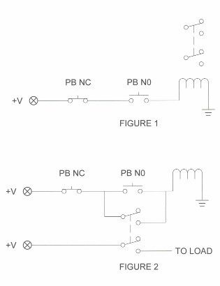
In Figure 2, I move the DPDT contacts. One set of contacts wrap around the NO PB. When you push the NO PB, the relay turns on, the contacts close. Let go of the NO PB and the relay stays on. (the NO PBi is bypassed by the relay contacts) IOW It is self latching. The second relay contacts make a SPDT switch that you can turn On/Off anything you like.

This is where the NC PB comes in. First: press the NO PB, the relay turns on, the relay self-latches. press the NC PB, the switch opens, current through the relay coil is killed, the relay turns off and the contacts go to the relay off position.

The buttons can be anythings you like. As long as they are momentary style buttons. If you want to use a big red mushroom "panic" button for the off switch you can do that.

You have made a spiffy On/Off switch. One button is On, the other button is Off. Spiffy, sure, but why go to all that trouble to make an On/Off switch? What else can you do with it?

Figure 3 shows that you can add multiple On/Off buttons. On buttons go on parallel with each other, Off buttons in series.

You can add them in any combination you like. 2 On buttons, + 3 Off buttons. You can turn the system on with any On button and turn it off with any Off button.

Put an On button & an Off button on your panel, add a second Off button anywhere else in your brewery. E.g. An Off button on the far end of your brewery, away from your panel. You can shut things down, pronto, without walking over to your panel.

The switches can be any switch rated to carry the relay coil voltage. Use a key switch in the Off series switches. If the key switch is off, you cannot turn it on. Or make use a door lock out as an Off switch, when the door is open, the system is shut down.

yFig-4_zpsalkijlyu.jpg


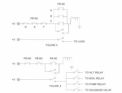
Figure 4 is an example of how you might use the switch. Use it to supply the control voltage for your SSR's. Put the coil for you 220 VAC contactor coil on the switched side and you can shut down all AC with the press of a button.

The current through the switches is the coil voltage only. If you use a 12 VDC relays you can safely run 12 VDC current all over you brewery.

The down side? You have to buy a relay and you need a power supply up and running in the first place to turn on the master relay.

I noticed one electric brewery supplier uses a variation of this switch. They run the coil current through the B-side of heater On/Off switches This forces you to have the heaters off before you can turn on the system. Clever and an excellent idea.
 
I have posted this here perhaps a dozen times and people studiously ignore it. They'll probably do the same to your post.

In the usual industrial setup (when I was involved in such things, anyway) the latching contact pair was usually an auxiliary on the starter/contactor that controlled the load.
 
I love this switch. In fact my new HERMS system will use this switch. I took the switches on the panel and have control surface with this On/Off push button design. Looks real cool, plus I can put repeat some functions at alternate locations. Like On/Off burner valves near the burner.

As an added bonus, I will have a Raspberry pi with the gpio to duplicate the On OFf switches via a web page. Or by way of any program I happen to want to try.
 
Agreed!
This concept is clearly laid out on page 3 of the sticky:
https://www.homebrewtalk.com/showthread.php?t=145019

I used it to build my control panel.

This thread is long but the OP ends up building a very nice and properly done (safe) control panel. He also uses a similarly designed E-stop circuit.
https://www.homebrewtalk.com/showthread.php?t=153310

So what is your point? I am supposed to feel stupid for duplicating information buried in a thread from >5 years ago? :D :mug:

And yet people still use the design of "pull the GFI to ground." If i can get one person to abandon doing that, it is worth my time and effort.
 
Perhaps, yet this horse has been beaten to death. :)
 
Being from an industrial electronics background myself, I have a master control relay as you've drawn.

Since there is no motion on my brewery - I dont have a mushroom E-Stop. One switch shuts it all down and thats good enough for me.
 
Being from an industrial electronics background myself, I have a master control relay as you've drawn.

Since there is no motion on my brewery - I dont have a mushroom E-Stop. One switch shuts it all down and thats good enough for me.

Your point has value.

Essentially this is a fancy toggle switch. Remember I did not present this not as a substiture of a toggle switch. This is an improved replacement for "induce a ground fault with a mushroom button" design.

I do not think you need motion to justify employing one of these switches. If you have boil over you can shut down the system, pronto. Or . . . . you put the heating element of you BK on a self latching switch, put a kill button for the element near the pot and stop the boil ASAP.

It has it's appliaction that some people will find useful.

For my upcoming design, I use a bunch of these switches and can interface with an Raspberry Pi in parallel. Either the R-Pi can latch and unlatch the switch or the panel can latch or unlatch a given switch. This allows me to experiment with different programs and go to manual control any time.
 
Forgive me if this has been discussed before. I am trying to evaluate the pros and cons of this type of emergency shut down vs "Induce GFI" emergency shut down. I was going to build the shut down as you describe here. However, with this method, there is still live power entering the control panel as all that was done was to shut off all panel functions. I thought that if there is a need to shut off in an emergency, it may be better to induce the GFI so no power at all is live in the panel.
 
A breaker is not meant to be purposely faulted in order to interrupt user power. It is a backup should the downstream wiring/circuitry fail. These leak-current e-stop designs that are rampant on this forum should be avoided at all costs. They work, but violate established safety standards.

Power into your panel should not be an issue. It is sealed and protects the user appropriately. It should be designed with circuit protection at each tier, aka each branch circuit.

-BD
 
Inducing a false fail to stop a different problem will never make sense to me. Yes. Creating a ground fault to stop a boil over or a smoking relay, close a NC valve, will work. You can defend it on a "it is better Han nothing" basis.

I am right tool for the job kind of guy. You can use a screw driver as a chisel. I am guilty of that. If given a reasonable choice, when you are talking about potentially dangerous voltage and/or our precious beer, short cuts are not worth it for me.

One advantage of this design it much more fail safe. If a connector gets knocked loose or a wire gets get cut, the system will not work. It has to be working properly to do it's job, an error forces you to correct it.

With the other design if the fuse blows, a disconnection happens, you will not learn of it until after the emergency has started.

You can choose what you want to shut down. What do you put on the off side of the switch? For me, I will not put Raspberry Pi and input power for my logic power supply on the switched side. When I hit the E-Stop, all the relays shut off power, valves close, PIDs etc shut down.

If you want to shut down your entire panel, put a master contactor at the ingress of you panel. Put the coil of the master contactor on the switched side the E-Stop. The down side is the power for the E-Stop relay coil cannot be powered off the contactor. An old cell phone charger and a $3.99 relay will remedy that.
 
I run the main coil through the NC contacts of my pumps and element as a safe-start. I'm really glad I did, as I try to power up my panel with some combination of these switches turned on quite often.

These concepts do fall on deaf ears but maybe this thread will help at least one person. It's marginally more time consuming to design and add some of these features but it's all up front. Just do it right once and use your panel for years.
 
A breaker is not meant to be purposely faulted in order to interrupt user power. It is a backup should the downstream wiring/circuitry fail. These leak-current e-stop designs that are rampant on this forum should be avoided at all costs. They work, but violate established safety standards.
+1.

I recently had BYO magazine remove this shunt to ground method from one of their schematics before going to print ... eventually we'll convince everything that this is not safe.

Thanks to the OP for starting this thread. The more the better.

Kal
 
Confused. Your pumps have contacts?

Sorry, the NC of the pump switches and the element switch, in series. All 3 switches much be off (the NCs closed) before the main contactor will latch. Once it has latched, power for the coil is backfed through the 2nd NO of the main power switch (which consists of 2 NO) and will stay latched until the power switch is turned off.
 
On my setup i have a big red mushroom button E-Stop. I have the NC contact on the E-Stop wired to the NO contact on my my main power switch and then to the coil on my main contactor. When i push the mushroom button the circuit is broken and the coil is de-energized and the contactor opens. I still have power coming in to the panel, but all elements, SSRs, pumps and the RaspPi lose power as they are powered from the main contactor that is now open.

Is that what you have here? Sorry I am learning a lot by following these threads and from doing my build and want to be sure i am doing things as safely as possible.

Is what you are showing here also that I could add in multiple E-Stops, say one near the kettle, to my system by wiring them in series with my current E-Stop?

I am confused by how you would use the multiple On switches in a panel. My panel is a Kal clone.

Hard to say exactly how your panel is wired. I am too new here to know what a Kal clone is.

Can you provide a link that has a schematic?

You would not use multiple on/off switches on the same panel. If you had a second location (away from the panel) and you wanted to turn things On/Off, you could do that. I do not know.... Maybe pump On/Off switches down near your pumps? Boil kettle On/Off switches near your BK?

That makes sense on the multiple On/Off switches.

A Kal clone is build based off of http://www.theelectricbrewery.com/ this site. Kal is a member here and a lot of members have base their electric setup builds off of his site.
 
That makes sense on the multiple On/Off switches.

A Kal clone is build based off of http://www.theelectricbrewery.com/ this site. Kal is a member here and a lot of members have base their electric setup builds off of his site.

OK, now that I have gotten away from work, I can see visualize what you did. Estentailly you put two switches is series to turn you main cntactor coil on and off. Both must be turn in the On position before you can power up your. system.

I assume you use a mushroom button that you slap to open the contacts (and shut down the system) and then you pull and twist the button to close (IOW reset) the system to on. Schematcially it is a toggle switch, but there are some fancy ergonomics assocaited with opening and closing the switch.

Nothing wrong with that design. Gives you a big easy target to slap and shut down the system in an emergency. Then you have to take specific steps to power the system back up.

If you wanted to add a second E-Stop button, say on the far end of your brewery, away from the panel, you would put a second switch in series with the first one. Slap either button the circuit is broken and the system shuts down

I assume the coil on your master contactor is 120 VAC. The current going through your E-Stop button is also 120 VAC. If you put E-Stop button #2, off your control panel, you will be running 120 VAC around your brewery. I will leave it to you to decide how you will mount a switch carrying 120 VAC and keep it safe from liquid and heat.

Let us say you want an E-Stop button away from your panel and you wish to avoid running 120 VAC around your brewery. Let us say you want to use 12 VDC as your control voltage. You would build Figure 2 in the OP, using a 12 VDC relay. The top left +V would be a 12 VDC power source that does not require the main contactor being on. The lower left point marked +V and lower right point marked as "To Load, that goes in series with your existing E-Stop button and contactor coil.

String as many Off buttons around your brewery as you like. I would put a single On button on your panel and mark it as "E-Stop Reset". You could replace your existing E-stop Button with a momentary push. Instead of pull and twist to reset it, you would use the new "E-Stop Reset" button.

Correct my coil voltage is 120 VAC. I had never thought of the idea of adding a 2nd E-Stop before reading your post, but it is an interesting idea.
 
I am correcting some wiring mistakes starting with my e stop. I am confused as how to wire my e stop and main contractor. All of my voltage is 120 and all of it is on the same circuit. The e-stop from Auberins is only rated for 10 amps, however my setup draws around 17 Amps. So my question is how do I wire my e-stop to my contactor? Normally I would just splice it into the hot leg, but sense the e-stop is only rated for 10 amps I cannot do that.
 
Why does everyone still insist on using E-Stop switches? E-Stop switches are for moving mechanical machines, you need a switch close by to stop it right away in the event something gets caught in it (hair, clothing, etc). On our brewing systems if your looking for a safety switch in the event of an electrical fire or the rig becomes electrified, the LAST thing you want to do is get closer to the rig to push a switch. You want to install a safety switch down stream, like half way between your fuse panel and your brewing control panel to get AWAY from the rig.


This is the right safety switch to use:

bf3007e9-4951-4851-86f1-f3f43e7709e4_400.jpg


http://www.homedepot.com/p/GE-60-Amp-240-Volt-Non-Fuse-Indoor-Safety-Switch-TGN3322/100676700


Because I want to use an e-stop...I don't care what it's "official" purpose is. I want I use it to cut off power at my control box. And I already have a downstream switch I can use.

What is so hard about answering my question? Especially because this entire thread is about e-stop designs.
 
I am correcting some wiring mistakes starting with my e stop. I am confused as how to wire my e stop and main contractor. All of my voltage is 120 and all of it is on the same circuit. The e-stop from Auberins is only rated for 10 amps, however my setup draws around 17 Amps. So my question is how do I wire my e-stop to my contactor? Normally I would just splice it into the hot leg, but sense the e-stop is only rated for 10 amps I cannot do that.

Let me see if I can help out here.

I am not sure what you are asking. When you say, E-stop, are you talking about a red mushroom panic button type of switch?

If so, that E-stop switch carries a small amount of current. Looking at the OP and Figure 1. The E-Stop would be the PB NO switch. The only current that passes through that switch is current required by the coil. The E-stop switch turns on the coil, (typically, coil current is less than 1 amp)the coil closes the relay/contactor the current passes through the closed contacts and system gets the juice.

That is the purpose of a relay/contactor, a small amount of control current (AKA coil current) can turn on and off a much higher voltage and higher current. Sorry if I am telling you stuff that you already know.

This assumes that you have a master relay/contactor that is common to all electrical components in your brewing system.

Switches come in many configurations and functions. Many of the E-Stop types I see are pull and twist to turn on and push to turn off. From a schematic diagram standpoint, they are a simple On/Off switch. It is specialized mechanics of turning it on and off that make it an "E-Stop+ switch.

If you have such a switch and you have a master contactor that turns the system on and off, all you need to do iis put your E-Stop switch in the position of the PB NO switch in Figure. Do not use the NC switch.

If your set up is more complicated, you will need to communicate what you have so we can sort it out to try and help you.
Text in red is incorrect. The use of NC contacts is what you want when using an EPO switch in the master contactor coil circuit. Activating the switch (hitting the mushroom) opens up the NC contacts, interrupting current to the contactor coil. You only want to use the NO contacts on the EPO if you are using a P-J style circuit (considered bad practice by many of the electrical experts around here) to trip the GFCI.

Brew on :mug:

Well, I now know where my error in wiring was. I had the NC E-Stop in series with both the contactor coil and the NO Contact of the contactor. So I was pulling the full load through my E-Stop and thats why it blew. So my first issue is I need to replace the NC block of my e-stop. Going to search Ebay. Then I'll rewire it correctly.
 
Why does everyone still insist on using E-Stop switches? E-Stop switches are for moving mechanical machines, you need a switch close by to stop it right away in the event something gets caught in it (hair, clothing, etc). On our brewing systems if your looking for a safety switch in the event of an electrical fire or the rig becomes electrified, the LAST thing you want to do is get closer to the rig to push a switch.

Probably because in an intelligent design you would have more than one located at various places. Certainly one on the panel in case something goes south while you are operating the panel but one at the entry to the room in case you have wandered off to get a beer and return to see your rig in flames, another at a second door if there is one, one next to the fridge, one in the garage, one in the bedroom, one next to the crapper.... That's the big advantage of this system. You can shut the thing off from anywhere you have had the foresight to place a button. You can also, of course, also put automatic protective devices in this series chain of mushroom buttons. One of those little button thermostats set to open at above say 220 °F on the kettle, another on the HLT etc. or a float switch or other level sensor would protect against boiling dry should you wander off to take a phone call from the White House, for example, and boil something dry.

The thing you showed a picture of is an emergency disconnect. Not an emergency stop button.

Yes, it's an emergency disconnect to cut all power to the rig....that's the point. One you pull down the other you push, both can be deactivated with the same force and speed. I rather have a mechanical emergency switch, like the one I referenced above, cutting off all electric rather than rely on a relay switch to do that but that's my preference and also because I'm an electrical engineer and I've seen my fair share of relays become shorted out and not disconnecting.

This whole thing reminds me of a Home Depot store right by me that mounted a fire extinguisher directly onto the cage that held all of the propane tanks...think about what's wrong with that scenario.
 
Yes, it's an emergency disconnect to cut all power to the rig....that's the point. One you pull down the other you push, both can be deactivated with the same force and speed.

Not really. It takes quite a bit more force to operate a disconnect than mash a button plus, as I indicated in my last post, if you are smart you will have a mushroom button at the panel, another one at each door into the room etc. You then eliminate the travel time to the disconnect from wherever you are when you discover the fault.

I rather have a mechanical emergency switch, like the one I referenced above, cutting off all electric rather than rely on a relay switch to do that but that's my preference and also because I'm an electrical engineer and I've seen my fair share of relays become shorted out and not disconnecting.
I used to design huge (as big as 40,000 amps) rectifiers for the electroplating industry and, of course, they used the traditional start/stop push button station to turn them on and off and they also had thermostats on each heat sink in series with the off button to shut the things down if something got too hot. I never saw a contactor weld in that application. But I have had them weld on me twice elsewhere in life. Once on an air conditioners compressor unit and the other was a fan control relay in a furnace. Guess what? In all these cases (including the rectifiers) there is a disconnect in the supply circuit! In most cases it is required (certainly in the case of the HVAC equipment) by code. And of course most of these guys that hook up a rig for electric brewing hook it to a spa panel which has a breaker that serves as the disconnect. Given that you have a low voltage control circuit with a start pushbutton it's just plain foolish not to have the emergency stop. The probability that a contactor will weld is very small and if it does you flip the breaker in the spa panel. Now if you wanted to put shunt trip breakers in the spa and main panels that would work nicely too. But install a separate emergency disconnect behind the breaker seems pretty silly to me but I suppose you can never have too many disconnects. I'd still put the pushbutton on the panel and elsewhere however. Perhaps that's just my training in the rectifier factory.

This whole thing reminds me of a Home Depot store right by me that mounted a fire extinguisher directly onto the cage that held all of the propane tanks...think about what's wrong with that scenario.
Can't come up with much. Obviously if I go there and see a big fire at the base of the cage I am not going to go up to it and grab the fire extinguisher to put it out but I'm not going to go get one mounted at a distance either! But if I see a fire in the vicinity of the cage that isn't large enough (yet) to threaten a burst I will very well go up to the cage and take the extinguisher to put it out before it gets large enough. Well let's be honest. I'm going to retreat in either case and call the fire department. I think you can rest assured that the propane tank exchange installations are very carefully regulated and monitored and that it has been determined that having a fire extinguisher mounted to the cage improves safety.
 
Back
Top