You are using an out of date browser. It may not display this or other websites correctly.
You should upgrade or use an alternative browser.
You should upgrade or use an alternative browser.
5500w ULD element taking too long to heat
- Thread starter Yambor44
- Start date

Help Support Homebrew Talk:
This site may earn a commission from merchant affiliate
links, including eBay, Amazon, and others.
No, they aren't. Green (ground) and white (neutral) are on opposite sides. That would explain it. Note: I'm color bind. Someone please check the picture.
To me it looks like the black wire is in "X", therefore the green wire and red wire positions need to be reversed.
However, before simply doing so, please physically ensure the terminal positions.
X = hot (black or red)
Y = hot (red or black)
W = neutral (white)
G = grounding (green)
However, before simply doing so, please physically ensure the terminal positions.
X = hot (black or red)
Y = hot (red or black)
W = neutral (white)
G = grounding (green)
Checked it myself with the computer's color meter. Red and green are reversed. To reiterate
Red to X or Y
Black to Y or X
White to W
Green to Ground
Red to X or Y
Black to Y or X
White to W
Green to Ground
jsguitar
Well-Known Member
To me it looks like the black wire is in "X", therefore the green wire and red wire positions need to be reversed.
Wouldn't that mean that only N and G are going to the PID though? It shouldn't be working. It might be an error on both sides of the input. I'm thinking the plug is also wired incorrectly.
I was just trying to figure out how the PID could be getting power and the element only getting 120V(if that's the case), hence the suggestion that L2 is actually N and N is actually L2. It seems to me that with the way this is wired that the PID/SSR might be switching neutral, creating the 120V opposite L1 at the element, with the swapped N and L2 lines providing power to the PID.
One thing is for sure, a multimeter is needed here!
OP
OP
I wonder if line 2 and neutral are switched around in the line coming in.
On the SSR?

$22.00 ($623.23 / Ounce)
AMZLMPKNTW Ball Lock Sample Faucet 30cm Reinforced Silicone Hose Secondary Fermentation Homebrew Kegging joyful
无为中南商贸有限公司


$44.99
$49.95
Craft A Brew - Mead Making Kit – Reusable Make Your Own Mead Kit – Yields 1 Gallon of Mead
Craft a Brew


$159.99 ($26.66 / Count)
3M High Flow Series System BREW120-MS, 5616001, For Brewed Coffee and Hot Tea, Valve-in-Head Design
SpaceCityProviders

$76.92 ($2,179.04 / Ounce)
Brewing accessories 1.5" Tri Clamp to Ball Lock Post Liquid Gas Homebrew Kegging Fermentation Parts Brewer Hardware SUS304 Brewing accessories(Gas Hose Barb)
chuhanhandianzishangwu


$53.24
1pc Hose Barb/MFL 1.5" Tri Clamp to Ball Lock Post Liquid Gas Homebrew Kegging Fermentation Parts Brewer Hardware SUS304(Liquid Hose Barb)
yunchengshiyanhuqucuichendianzishangwuyouxiangongsi


$479.00
$559.00
EdgeStar KC1000SS Craft Brew Kegerator for 1/6 Barrel and Cornelius Kegs
Amazon.com


$58.16
HUIZHUGS Brewing Equipment Keg Ball Lock Faucet 30cm Reinforced Silicone Hose Secondary Fermentation Homebrew Kegging Brewing Equipment
xiangshuizhenzhanglingfengshop


$172.35
2 Inch Tri Clamp Keg Manifold With Ball Lock Posts, Pressure Gauge, PRV (0-30 PSI) – Homebrew, Fermentation, Kegging System
wuhanshijiayangzhiyimaoyiyouxiangongsi


$28.98
Five Star - 6022b_ - Star San - 32 Ounce - High Foaming Sanitizer
Great Fermentations of Indiana


$20.94
$29.99
The Brew Your Own Big Book of Clone Recipes: Featuring 300 Homebrew Recipes from Your Favorite Breweries
Amazon.com


![Craft A Brew - Safale BE-256 Yeast - Fermentis - Belgian Ale Dry Yeast - For Belgian & Strong Ales - Ingredients for Home Brewing - Beer Making Supplies - [3 Pack]](https://m.media-amazon.com/images/I/51bcKEwQmWL._SL500_.jpg)

$33.99 ($17.00 / Count)
$41.99 ($21.00 / Count)
2 Pack 1 Gallon Large Fermentation Jars with 3 Airlocks and 2 SCREW Lids(100% Airtight Heavy Duty Lid w Silicone) - Wide Mouth Glass Jars w Scale Mark - Pickle Jars for Sauerkraut, Sourdough Starter
Qianfenie Direct


$176.97
1pc Commercial Keg Manifold 2" Tri Clamp,Ball Lock Tapping Head,Pressure Gauge/Adjustable PRV for Kegging,Fermentation Control
hanhanbaihuoxiaoshoudian


$719.00
$799.00
EdgeStar KC2000TWIN Full Size Dual Tap Kegerator & Draft Beer Dispenser - Black
Amazon.com

$10.99 ($31.16 / Ounce)
Hornindal Kveik Yeast for Homebrewing - Mead, Cider, Wine, Beer - 10g Packet - Saccharomyces Cerevisiae - Sold by Shadowhive.com
Shadowhive


$7.79 ($7.79 / Count)
Craft A Brew - LalBrew Voss™ - Kveik Ale Yeast - For Craft Lagers - Ingredients for Home Brewing - Beer Making Supplies - (1 Pack)
Craft a Brew

$53.24
1pc Hose Barb/MFL 1.5" Tri Clamp to Ball Lock Post Liquid Gas Homebrew Kegging Fermentation Parts Brewer Hardware SUS304(Gas Hose Barb)
Guangshui Weilu You Trading Co., Ltd


jsguitar
Well-Known Member
On the SSR?
No, I mean the RED L2 and the WHITE Neutral coming into the panel could be switched. As said, you really need to check your wiring on the input plug and the wires coming into the panel with a multimeter on the ohm setting to make sure everything is what it's supposed to be. Maybe the outlet too (to be more clear; checking voltage at outlet) if that's been rewired recently. Just don't go swapping any wires until your sure what's what.
OP
OP
No, I mean the RED L2 and the WHITE Neutral coming into the panel could be switched. As said, you really need to check your wiring on the input plug and the wires coming into the panel with a multimeter on the ohm setting to make sure everything is what it's supposed to be. Maybe the outlet too (to be more clear; checking voltage at outlet) if that's been rewired recently. Just don't go swapping any wires until your sure what's what.
Okay. The wiring is correct inside the panel box; meaning it matches the diagram.
I will have it checked starting at the wall outlet. Here is a pic of the switch and how the numbers correspond with the diagram as well as On/Off. Don't know if it matters, just thought I'd throw it out there just in case.
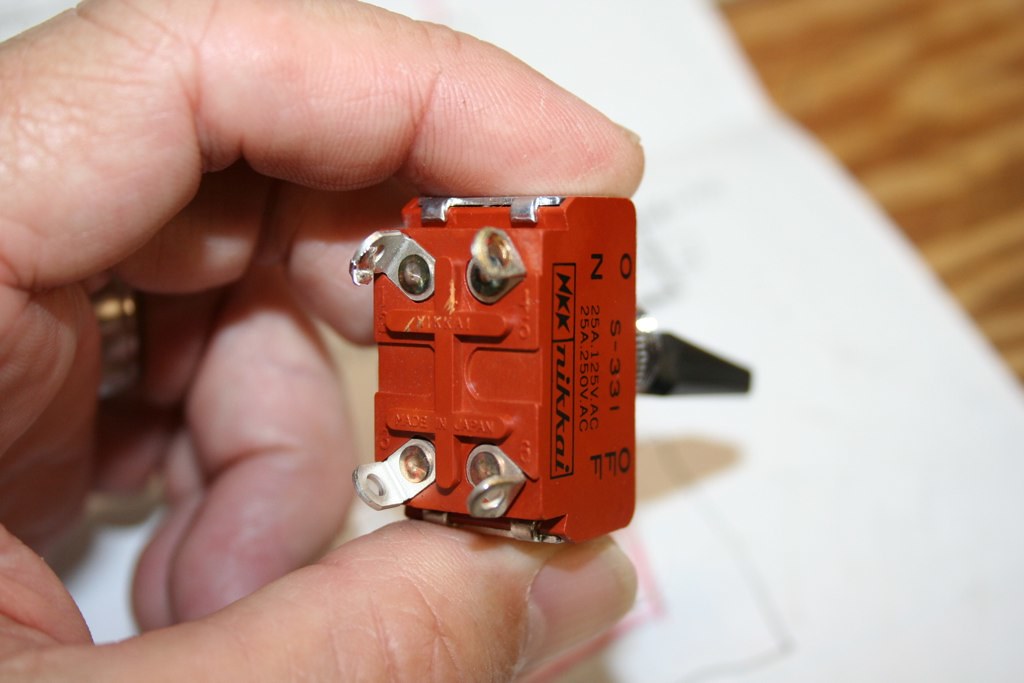
The diagram shows
L2 - controller - N and L1 - heater - L2
Reversing N and L2 gives
N - controller - L1 and L1 - heater - N
The picture makes it clear that a hot and the neutral have been reversed. N and L2 explains what he is seeing. Reversing N and L1 gives
L2 - controller - L1 and N - heater - L1
and this also explains what he sees provided the controller is capable of operating with 240V primary power.
OP
OP
OP
OP
Maybe this will help some?
Last edited by a moderator:
Okay. The wiring is correct inside the panel box; meaning it matches the diagram.
But the picture shows the red and green wires next to each other on the power in connector. On NEMA split phase plugs W and G are opposite at least the pins are unless G is in the center in which case I suppose the terminals could be adjacent. Can you confirm W to white and G to green? If you can then we have to go back to the list in #30.
The video confirms that the out light is on continuously (although the default cycle time is, I think, 100 seconds) so suspicion focuses, at this point on the external wiring or the SSR (given positive confirmation of the power connector wiring).
jsguitar
Well-Known Member
Reversing N and L1 gives
L2 - controller - L1 and N - heater - L1
and this also explains what he sees provided the controller is capable of operating with 240V primary power.
Yeah, that makes sense too. This PID does also operate at 240V.
OP
OP
The diagram shows
L2 - controller - N and L1 - heater - L2
Reversing N and L2 gives
N - controller - L1 and L1 - heater - N
The picture makes it clear that a hot and the neutral have been reversed. N and L2 explains what he is seeing. Reversing N and L1 gives
L2 - controller - L1 and N - heater - L1
and this also explains what he sees provided the controller is capable of operating with 240V primary power.
This is what I see on the diagram (in laymans terms
 ):
):L2 (red) goes to SSR 1 which goes to the switch 1 and out 3 to PID 10, out 8 to SSR 4, out SSR 2 to the element plug.
N (white) goes to Switch one at 4, out 6 to PID 9
L1 (black) comes in and goes straight to element plug.
Here's a couple more pics from during the build. Maybe a better vantage point.
I really appreciate everyone's input and help!


OP
OP
Originally Posted by ajdelange View Post
Reversing N and L1 gives
L2 - controller - L1 and N - heater - L1
and this also explains what he sees provided the controller is capable of operating with 240V primary power.
Yeah, that makes sense too. This PID does also operate at 240V.
Yeah, that makes sense too. This PID does also operate at 240V.
So are you guys saying I need to have N (white) go straight over to element plug and L1 (black) go to switch one 4 out from 6 and over to PID 9?
This would make a ground, Neutral and hot (red) going to element?
OP
OP
The video confirms that the out light is on continuously (although the default cycle time is, I think, 100 seconds) so suspicion focuses, at this point on the external wiring or the SSR (given positive confirmation of the power connector wiring).
I am sure the power in wire is wired exactly like the power in outlet on the control panel.
How can I tell if I have the element wire wired wrong other than a meter?
jsguitar
Well-Known Member
Is there any way you can run out to a Home Depot and get a multimeter? I think trying to figure this out without one is just dangerous.
What we are trying to confirm is that the white wire from the input connector is connected to the terminal marked W, that the green wire is connected to the terminal marked G and that the other two (black and red) are connected to the X and Y terminals. We'll keep asking that question until we get an answer because that is the only way, other than measurement, that we might be able to figure out what's going on. I cannot see the terminal markings from the photographs.
But I agree with the sentiments about getting a meter.
But I agree with the sentiments about getting a meter.
I kinda got lost here, what are you trying to figure out? 240 to the element?
My .02 cents, I'm running a 4500w uld off of an auber 4342 @ 120vac and I heated roughly 3 gallons to 145 in about 15 minutes and that is from 58 degrees starting temp. I don't know if that helps. I am curious how this thread goes as I just fried my pid and just ordered a 4352 with the ramp/soak option. The 4342 says it can handle up to 10 amp loads, I did the math and the element at 1/4 power was just under 10 amps. Well, tell that to the melted spot in the side of the pid. Now I'll go through a relay and hopefully nothing else will melt.
My .02 cents, I'm running a 4500w uld off of an auber 4342 @ 120vac and I heated roughly 3 gallons to 145 in about 15 minutes and that is from 58 degrees starting temp. I don't know if that helps. I am curious how this thread goes as I just fried my pid and just ordered a 4352 with the ramp/soak option. The 4342 says it can handle up to 10 amp loads, I did the math and the element at 1/4 power was just under 10 amps. Well, tell that to the melted spot in the side of the pid. Now I'll go through a relay and hopefully nothing else will melt.
OP
OP
What we are trying to confirm is that the white wire from the input connector is connected to the terminal marked W, that the green wire is connected to the terminal marked G and that the other two (black and red) are connected to the X and Y terminals. We'll keep asking that question until we get an answer because that is the only way, other than measurement, that we might be able to figure out what's going on. I cannot see the terminal markings from the photographs.
But I agree with the sentiments about getting a meter.

and the other side showing Y which leaves only G for green down below.

Does this help or eliminate anything?
Let me throw this back in so you don't have to go back and look.

jsguitar
Well-Known Member
That looks right.
Can you post an internal pic of the plug that plugs into that also? It might help.
Can you post an internal pic of the plug that plugs into that also? It might help.
OP
OP
That looks right.
Can you post an internal pic of the plug that plugs into that also? It might help.
I may have found the culprit. Not sure yet though. I checked the ends of my element wire (the wire that runs from the element to the back of the control panel. When I took apart the Swicthcraft housing to double check the wiring, one end came completely off. so I am hoping one of those wire either were not making a good connection or not at all.
Could this cause the problem?
This is what I am using.
https://www.homebrewtalk.com/f170/switchcrafts-plug-outlet-option-369044/
If the wiring in the control exactly matches the schematic then it must be either in the output plug to element wiring/connections or the input plug/power supply connections.
What connector is that at the inlet? Have a brand and model number?
What connector is that at the inlet? Have a brand and model number?
Garyr2973
Well-Known Member
That still must be a strange plug. Usually the "A" and "B" hots are at the 3 and 9 o'clock position and the neutral and ground are at the 12 and 6 position (if the plug is orientated straight"
Garyr2973
Well-Known Member
Even looking at the wiring diagram it shows the 2 hot wires across from each other but that's not how it appears to be wired in the picture of the actual plug.
Garyr2973
Well-Known Member
Oops. Guess I should have specified the blue ink pen part at the top of the page looks like a typical 220 plug.
OP
OP
Oops. Guess I should have specified the blue ink pen part at the top of the page looks like a typical 220 plug.
That's the Switch craft plug.
OP
OP
That looks right.
Can you post an internal pic of the plug that plugs into that also? It might help.

And I think THIS may be the problem? Notice the black and red are not where they should be compared to the power inlet pic above? Could it be this simple? If so, I assume just reverse them?

And just in case, the other end of the cord:


I agree the colors should match through the connectors so I'd swap them (re: second pic showing red in "X"), but that isn't the problem.
The wires in the big black plug look right.
At this point, assuming you've not run out and picked up a meter, I think re-checking the output plug and cord and element are about all that's left for physical inspection. I know you said one of the terminals is off...fix that, then ensure the wiring matches up going through the output jack and plug.
Similar threads
- Replies
- 25
- Views
- 3K
