Sam's Brew Box

Homebrew Talk - Beer, Wine, Mead, & Cider Brewing Discussion Forum

Help Support Homebrew Talk - Beer, Wine, Mead, & Cider Brewing Discussion Forum:

This site may earn a commission from merchant affiliate links, including eBay, Amazon, and others.

sam

Well-Known Member
Joined
Dec 18, 2004
Messages
110
Reaction score
31
Location
Bridgewater, NJ
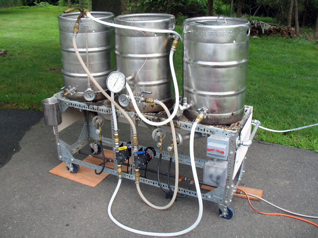
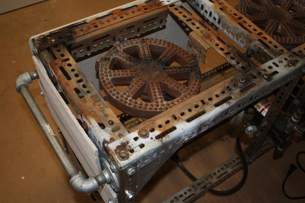
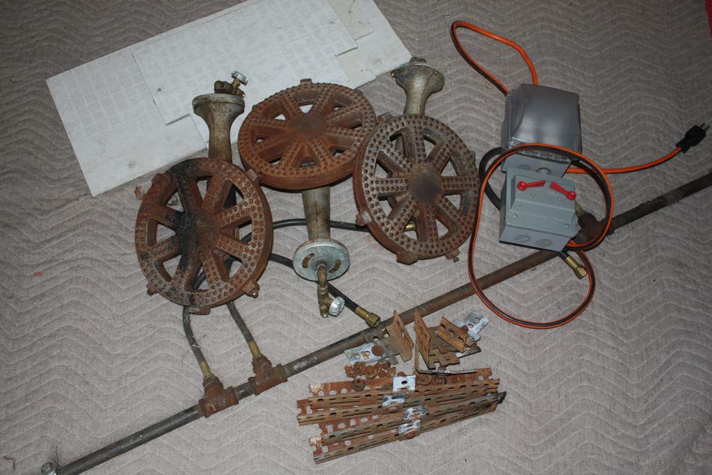
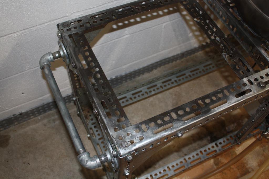
I'm ready for a new project! I've found myself spending more and more time reading threads about electric brewing and have been inspired by the builds here. Time to pull the trigger and convert my old single-tier direct fired mash system. I brew in fits and starts and I'm hoping that converting over to electric and bringing it inside will allow me to brew more regularly.

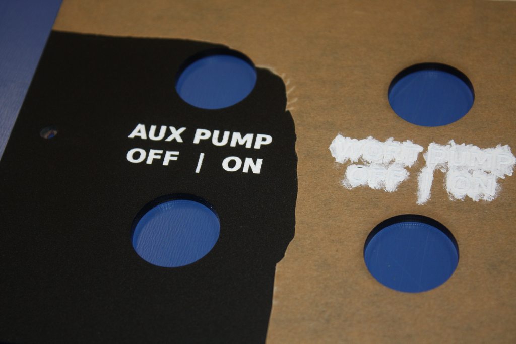
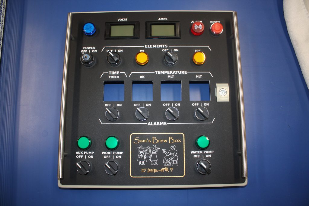
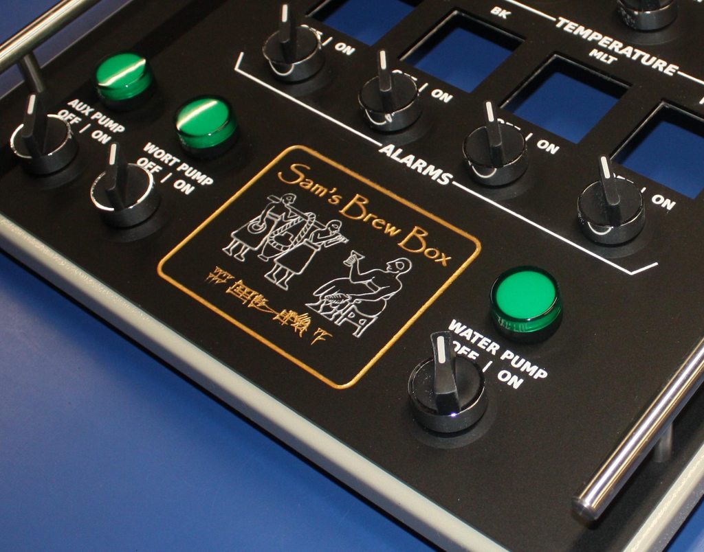
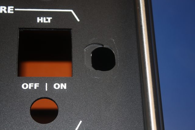
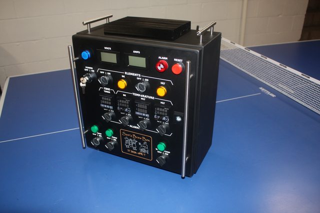
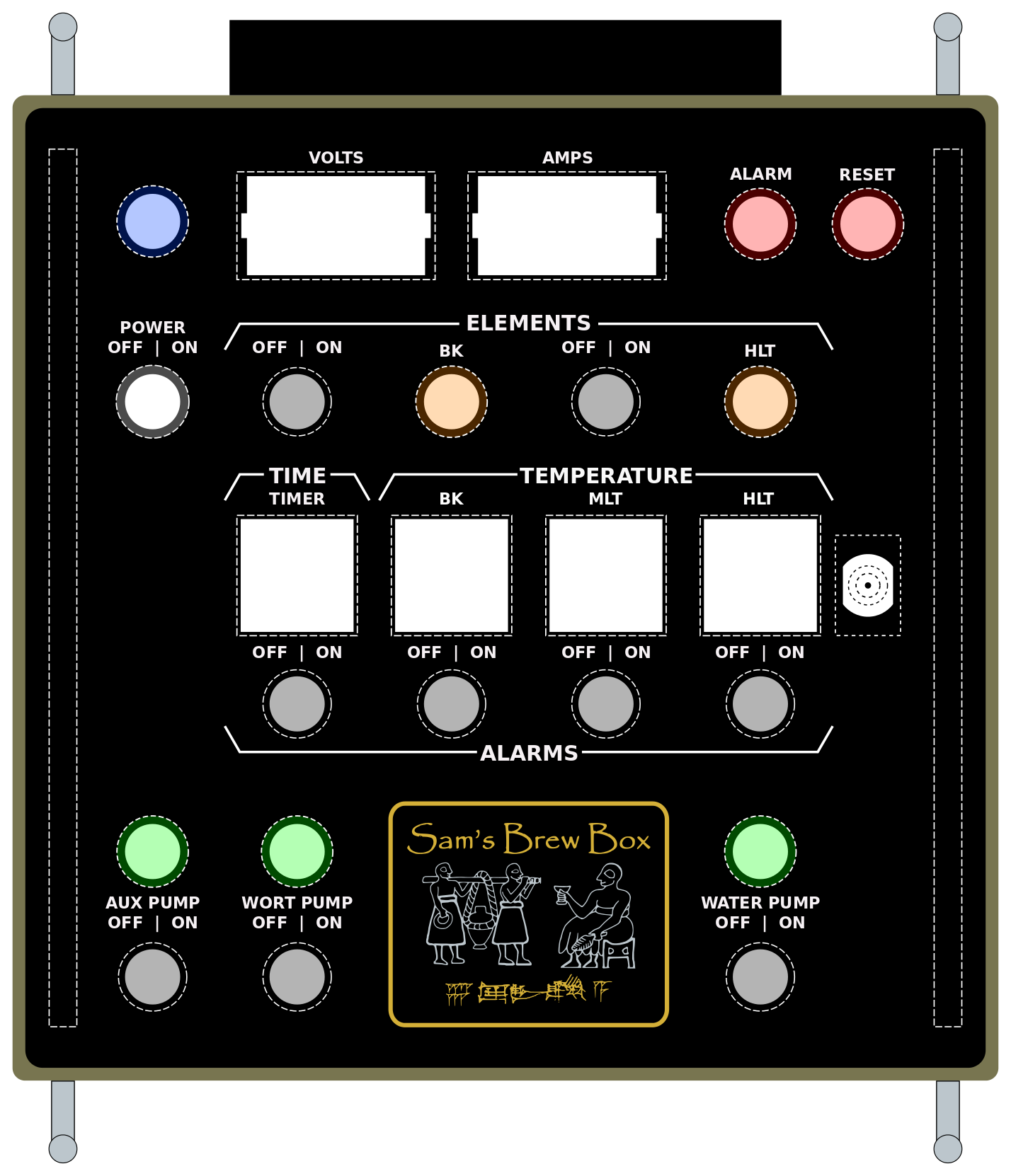
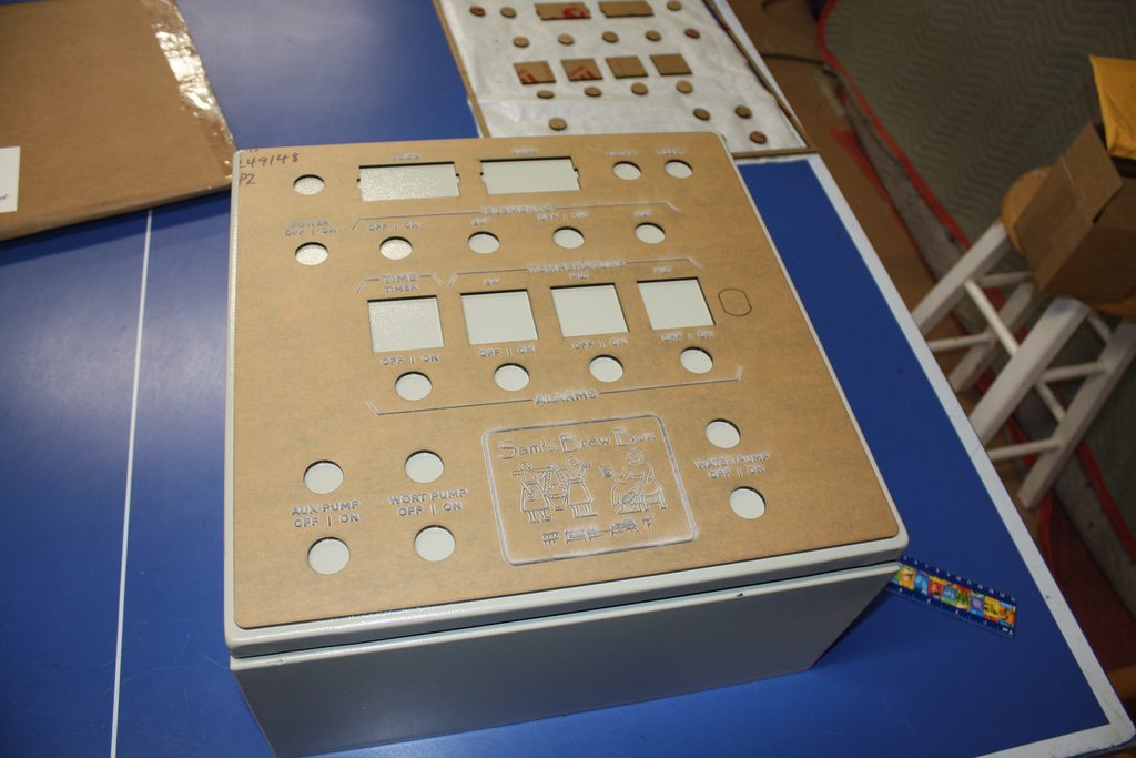
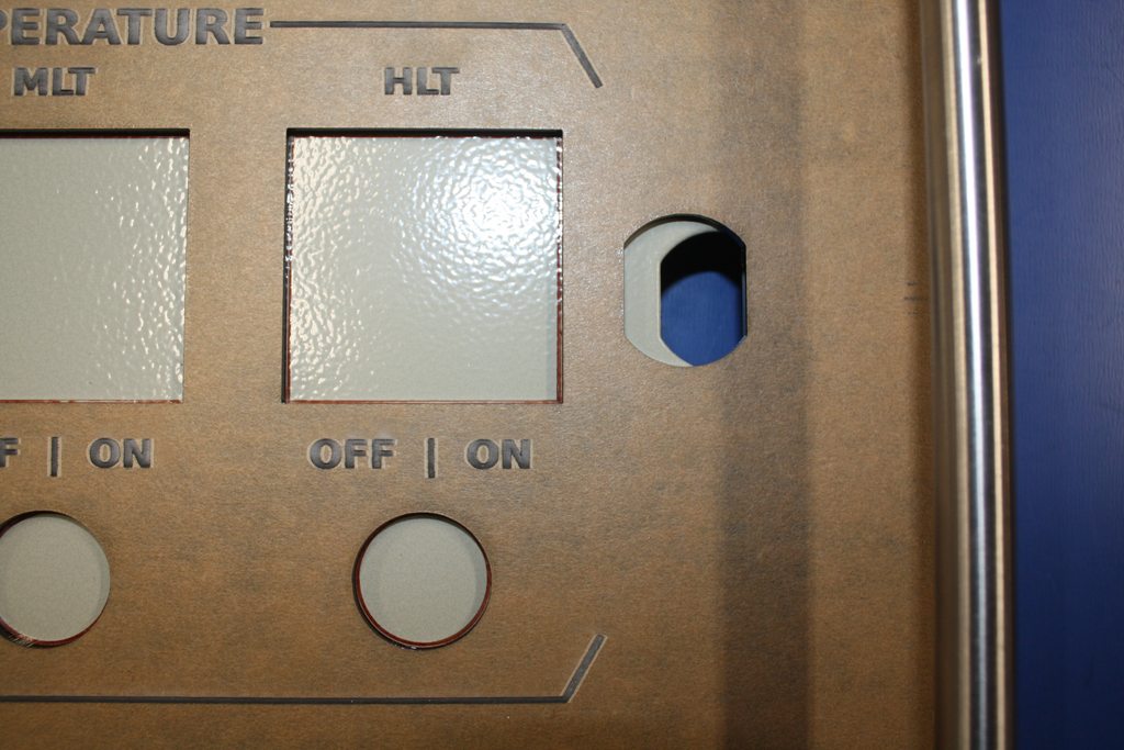
I purchased Kal's guide a while ago and have been sourcing the parts myself; planning on a 50A back-to-back setup with an extra pump. One thing I wasn't too keen on was the look of the panel tags. I came across ponoko.com and decided to have a piece of acrylic cut and engraved. Below is layout I came up with.

I used Inkscape to design the layout and posted the file here in case anyone wants to use it.

The ponoko formatted files can be found here and can also be used freely.

Ibmb9PZ.png
 
@Deece - I've come across your panel a few times; very nice!

Here's the stand I'm working with... built it about 7 years ago. I'll strip off the burners and other unnecessary items; will have to drill a few new holes in the kettles.

DNIOISU.jpg


.
 
Just a patina of rust...

WYvdIBG.jpg


Stripped off 71 lbs (32 kg)... yes, I weighed it.

WZbwCtN.jpg


Angle grinder with wire brush to clean it up...

4bQeaPw.jpg
 
Made some progress on the element holes for the HLT and boil kettle. I couldn't find the $60 step bit I bought 7 years ago so I used the step bit kit from harbor freight. I wasn't too sure they would be able to do the job but I was wrong... I used a little 3-in-one oil for lubricant and the HF bits cut beautifully.

PfBKgWN.jpg


I soldered on one of Bobby's radius-faced 1.5" tri-clover flanges following his how-to video. I didn't realize I was a little light on the solder in one section until I cleaned it up; ended up with a pin-hole sized leak. It was easily fixed by adding a tad more flux and re-flowing the solder.

These are pictures of the HLT...

b9nhHEW.jpg


4uHOgyz.jpg


WWAP1n5.jpg


Fixed the leak indicated below; a little more flux and solder did the job.

m0XqWvr.png


Besides a couple of scratches, the inside looks pretty good too...

Omn3nHo.jpg
 
Ponoko.com acrylic panel delivered...

6cRJLchh.jpg


I popped in a few components; they all fit perfectly.

LztMuZjh.jpg


fGtvBmdh.jpg


2TBgLLWh.jpg
 
One mistake on my part...

I had been printing out my design at full size using tiled pdfs to make sure things fit properly on the front of the enclosure. Right before submitting my design to Ponoko, I decided to move everything 7mm to the left and 2mm up; it looked a little more balanced that way. Because I didn't bother printing it out and checking the fit one last time, I didn't realize I had accidentally moved the cut-out for the enclosure's latch hole. You can see the mistake in the picture below.


GN9ghDUh.jpg


It's not too big a problem... The bezel will cover most of the mistake and I'll glue a piece back in to fill the remaining gap.

In hindsight, I shouldn't have even bothered laser-cutting a hole for the latch. I discovered that the acrylic sands nice and clean using a dremel with a little drum sander bit (I tested on a scrap piece). So, after mounting the acrylic panel to the enclosure, I could have drilled a hole from the back of the enclosure door through the latch hole and used the dremel to clean it up.
 
Any reason you didn't use a combo push button/LED light on the bottom row?

Actually, I did consider the button/led combos when I was laying things out but I decided I liked the look of Kal's design so I stuck with the separate switches and pilot lights.
 
Used the panel as a template for the holes in the enclosure; tried to keep the drill bit in the center of the circles (even used a punch) but had a hard time as you can see below. Gotta love the 22mm punch!

iPDyNkbh.jpg


Od35xuqh.jpg


G1cucbIh.jpg
 
I was anxious to see how the color fill would look and whether or not it would bleed under the paper and onto the matte surface. I'd guess paint on the matte surface would be harder to clean up than on glossy acrylic.

So far, so good. :)


SR8hWkXh.jpg
 
That turned out amazing! Good luck with the rest of it. I may have questions for you once I start putting my panel together.
 
Thank you for posting the files for free!!!! It looks awesome and I love the layout. I hope to get one made with your layout soon. I was wanting one very similiar to yours after seeing the Black Heart Brewery thread, I just don't know how to use the software to create the drawing. Thanks for your hard work in the awesome design!!!!

Just need to figure out how to get my brew logo in there!

Great job, looks great. Keep us posted please!!!!

I can certainly help you with the file... the one mistake I made was to try to match up the latch hole with the drawing... definitely no need to do that (I'll post a picture of the fix later). I should probably create a generic file that matches up with Kal's design. The engraved acrylic was much cheaper than buying all of those panel tags.
 
My cable tray was not flat (like the one shown on Kal's site) and the heat sink that I got from Auber wouldn't sit correctly. I can't find the thread now but I copied what someone did here by flattening the ridge of the cover plate with a hammer and grinding off some high spots on the enclosure so the top laid flat. Then, I used JB Weld to secure it and get everything smooth. It took two applications of JB Weld... I didn't get a pic but I put the first bead of JB Weld down and screwed on the cover. After it hardened, I ground off the screw heads and used the second application of JB Weld like spackle.

i1T6oINh.jpg


y4eVGUHh.jpg


Smooth now with cut-out for SSRs and holes for mounting heatsink...
CRhd1WUh.jpg


That white spot is some marine epoxy... I ran out of JB Weld and had to fill a low area.
 
I really hate cutting holes in this thing; it's a big pain in the arse!

yQFstWdh.jpg


ZlJKPmoh.jpg


g3VGjaMh.jpg


XFXTbrjh.jpg


Finally! I think I'm ready for painting.
 
Forgot to post this earlier... I had to move the ground post on the door and this is what I came up with...

Y4dQI1Ul.jpg


b7ZFcpMl.jpg


JznrXHil.jpg


.
 
I am jealous. looks good man!

looks pretty sweet man.

Thanks guys! I should be able to post some more pictures with all the external components mounted tonight.

That will leave the guts... Do I actually need a wiring diagram? I understand (for the most part) how to wire this thing up... I started laying out a diagram in Visio but I'm not familiar with the program. It seems like I'll spend more time wrestling with Visio than actually building.

.
Good luck... I didnt even draw up a diagram for mine. Just wired it up paying attention to what does what as I went... I will say the next panel I build will have color coded wires as mine is a confusing mess when ever I open it up to upgrade or add something.
 
Thanks guys! I should be able to post some more pictures with all the external components mounted tonight.

That will leave the guts... Do I actually need a wiring diagram? I understand (for the most part) how to wire this thing up... I started laying out a diagram in Visio but I'm not familiar with the program. It seems like I'll spend more time wrestling with Visio than actually building.

.


OK, well, I got the hang of Visio and posted a diagram here: https://www.homebrewtalk.com/showthread.php?p=7716187#post7716187

Looking for some feedback.

Thanks!
 
OK, here's how I patched my laser cutting mistake... just glued the scrap piece in and used a dremel sanding drum to grind it down to the same size as the hole in the enclosure.


HiXU3wbl.jpg


uzoBT2Nl.jpg


Needs a little more sanding here...
j4Zi95al.jpg


Finished and cleaned up with some acetone...
OK2rdfhl.jpg
 
What receptacle are you using on your incoming power to your control panel? It looked like a three prong input. Then using a 50amp stove receptacle on the wall?
 
What receptacle are you using on your incoming power to your control panel? It looked like a three prong input. Then using a 50amp stove receptacle on the wall?

These are twist lock connectors. It's hard to see the ground in my previous pictures. The ground is on the outside of the connector and lines up with the ground on the flanged inlet when they're twisted together.

Here's how I go from wall to panel:
0UJuGmYt.png
->
p73aevRt.png
->
Wk5sVZvt.png
->
v37YxOXt.png


Inside panel wire connections:
ZCjewPBt.png


Links:
 
Last edited by a moderator:
Back
Top