BrewPi@ESP8266, no need of RPI and Arduino.

Homebrew Talk - Beer, Wine, Mead, & Cider Brewing Discussion Forum

Help Support Homebrew Talk - Beer, Wine, Mead, & Cider Brewing Discussion Forum:

This site may earn a commission from merchant affiliate links, including eBay, Amazon, and others.
IMO, rotary encoder is hard to handle.
First, it can't be processed in polling mode, unless the system runs nearly nothing.
Second, the debounce capacitors are needed, but even with the debounce capacitors, it doesn't feel like silk smooth.

The solo advantage I know is that only one small opening is needed.

I've supported the rotary encoder by IO expander, but I would rather use the web interface, which is easy and simple.

That's not strictly true. Debouncing capacitors are not needed as the output of the encoder is a Gray code, where only one bit changes at a time. So a bounce will move you between two valid states, eventually settling on the new state. Also, the software can be polled or interrupt-driven. Polling with a rate of a few milliseconds is fine (my code sleeps 1ms between polling).

My rotary encoder has about 12 or 16 physical clicks per revolution, but each click cycles through all four Gray codes. So I track the codes to get direction and an 'internal' count, then I divide the internal count by four for the reported count.

Thank you for your information. I have limited knowledge about rotary encoder.
Regarding the polling mode, I didn't make clear statement. I did mean that polling in MAIN LOOP is nearly impossible since the time period between each poll might be something like a hundreds milliseconds.
 
Thank you for your information. I have limited knowledge about rotary encoder.
Regarding the polling mode, I didn't make clear statement. I did mean that polling in MAIN LOOP is nearly impossible since the time period between each poll might be something like a hundreds milliseconds.

Ah, yes, hundreds of ms would be too long. I think less than 10ms would probably be ok.

Is there any internal timer interrupt you can use? Set it to roll over every few milliseconds and then sample the encoder independently of the main loop?
 
Ah, yes, hundreds of ms would be too long. I think less than 10ms would probably be ok.

Is there any internal timer interrupt you can use? Set it to roll over every few milliseconds and then sample the encoder independently of the main loop?

Per my last survey, it's not possible to use timer interrupt for rotary encoder, but I lost the link. It seems like that the ISR will result in heavy loading of system and affect the WiFi functionality. It really doesn't mater, because rotary encoder can be supported by interrupt of RA, RB, and PushDown button. The problem for ESP8266 is lack of available PINs.
 
Per my last survey, it's not possible to use timer interrupt for rotary encoder, but I lost the link. It seems like that the ISR will result in heavy loading of system and affect the WiFi functionality. It really doesn't mater, because rotary encoder can be supported by interrupt of RA, RB, and PushDown button. The problem for ESP8266 is lack of available PINs.

I just bought one of these things to play with the "3 button" method of emulating the rotary encoder:

https://chicagodist.com/products/membrane-1x4-keypad-extras

I figure we have 2 free pins plus the unused buzzer pin, so why not?

If it works, I'll try to come up with something less ugly hardware wise.

I see no reason why it won't work.
I have that keypad and had thought about it, but I don't really need it.

Allow me to remind you that the menu handling uses another loop which will result in WDT timeout. The solution is simple by adding a "delay(1)" in the loop. It's strange that reseting the WDT doesn't seem to work.

Interesting. I know I had that issue when first porting the controller code over - hence why I have yield(); all over the place. Thanks for the heads up on the second loop - I almost certainly would have missed that and would be back here complaining about how nothing works.
 
Interesting. I know I had that issue when first porting the controller code over - hence why I have yield(); all over the place. Thanks for the heads up on the second loop - I almost certainly would have missed that and would be back here complaining about how nothing works.

It's interesting that I had managed to add WDT to my Arduino build but I didn't handle the menu loop. When the WDT timeout happened on ESP8266, it's all familiar to me, and I felt comfortable for a while before I realized that I didn't handle the WDT. :)
 
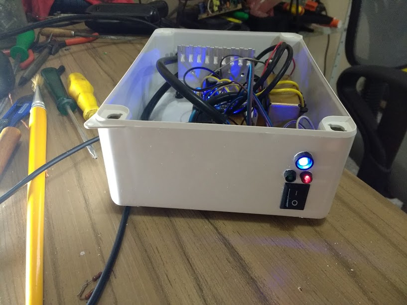
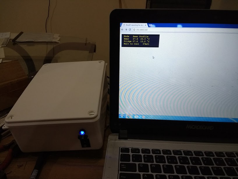
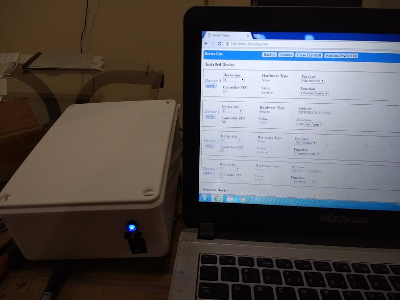
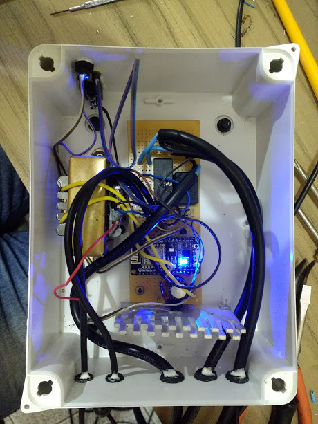
Some pictures !!

IMG_20170131_221007277.jpg


IMG_20170131_221018108.jpg


IMG_20170131_221027206.jpg


IMG_20170131_221044786.jpg


IMG_20170131_221619495.jpg


IMG_20170131_221637887.jpg


IMG_20170131_221653998.jpg
 
there is nice ESP board with 16M - https://www.aliexpress.com/item/Nod...-16M-flash-USB-serial-CP2102/32779742446.html

They have also other versions of the ESP in their shop there. I was using their Arduino Nano clones with microUSB which are great and great quality as well.

Old NodeMcu(V1.1) and WeMos D1 mini use ESP-12E while this "V3" NodeMcu and WeMos D1 Pro seem to use ESP8266 directly. The BOM cost should be reduced, and they can use a larger FLASH.

IMO, one advantage of using ESP-12E is the shielding. I am not sure how the WiFi works without shielding on this "V3" NodeMcu. (I do buy a WeMos D1 Pro, but I am too lazy to solder the header PINs.)

The rumor I read had the WeMos D1 Pro's WiFi actually underperforming the WiFi on the D1 Mini in terms of signal strength. I'd be curious how the "V3" NodeMCU compares in that regard. I've got both the mini & pro soldered up & flashed, and haven't noticed much of a difference. That said, my apartment is also tiny, so there's not much room to test.

Additionally, not that it matters much to anyone in this thread I'm sure, but the D1 Pro/V3 NodeMCU don't have the FCC stamp the D1 mini has.
 
I have no problem with those new versions in my other projects at all, not sure if they perform better but at least not worse. I think there is new ESP chip which should be much better but I didn't test it yet.

Are those relays http://sc01.alicdn.com/kf/HTB1p7ZlK...ngle-Relay-SRS-05VDC-SL-C-SRS.jpg_350x350.jpg
enough for the project? Or SSR would be better? Also using a transistor is recommended or it is completely fine to run them directly from ESP gpios?
 
The rumor I read had the WeMos D1 Pro's WiFi actually underperforming the WiFi on the D1 Mini in terms of signal strength. I'd be curious how the "V3" NodeMCU compares in that regard. I've got both the mini & pro soldered up & flashed, and haven't noticed much of a difference. That said, my apartment is also tiny, so there's not much room to test.

Additionally, not that it matters much to anyone in this thread I'm sure, but the D1 Pro/V3 NodeMCU don't have the FCC stamp the D1 mini has.

I worked in Wireless industry as a software engineer. The only thing I know about RF is that it is hard to design. Most of the products with RF I have seen use shielding. My concern isn't really about the WiFi performance but the RF interference. If it works fine for others, I bet I am cool with it.
 
I have no problem with those new versions in my other projects at all, not sure if they perform better but at least not worse. I think there is new ESP chip which should be much better but I didn't test it yet.

Are those relays http://sc01.alicdn.com/kf/HTB1p7ZlK...ngle-Relay-SRS-05VDC-SL-C-SRS.jpg_350x350.jpg
enough for the project? Or SSR would be better? Also using a transistor is recommended or it is completely fine to run them directly from ESP gpios?

The relay in the link is 10A capability, which is fine for most fridge and freezer. You, however, have to check your own fridge or freezer.

As far as I know, compared to mechanical relay, SSR is more expensive and bulkier with heat sink. However, it has some important advantages:
- larger current support, like 25A~40A.
- (usually) zero-crossing switch, so less interference. Some people, like me, have scrambled LCD issues caused by switch of mechanical relays.

To drive relay or SSR, enough driving voltage and current is required. The SSRs I have require 3~32VDC and around 10mA(?) driving current. They work fine with ESP GPIO. Mechanical relays seem to require higher current. You have to check the specifications to find out. I would suggest to use relay modules instead of relays to go with ESP GPIOs.
 
But the mechanical ones I can fit in my PCB :) Relay module is just with transistor and diode and LED which I can design on my own PCB without a problem. Just wanted to ask if there is any potential harm with them like for ArdBir they are not perfect with PWM signal and not fast enough (?) and also LCD problem which you mentioned. For BrewPi(Less) this should be a problem as there is no LCD :)
 
But the mechanical ones I can fit in my PCB :) Relay module is just with transistor and diode and LED which I can design on my own PCB without a problem. Just wanted to ask if there is any potential harm with them like for ArdBir they are not perfect with PWM signal and not fast enough (?) and also LCD problem which you mentioned. For BrewPi(Less) this should be a problem as there is no LCD :)

Not that I know of.
BrewPi(Less) won't switch the compressor or heater quickly. There is a three minutes delay to protect the compressor and to prevent heating/cooling vibration.
 
I did end up getting this ESP8266.

I have managed to get it flashed and reporting but on brewpi.local/ the lcd starts and within a couple minutes always goes to "Controller not updating data..." then i have to refresh. Now I believe I have done everything correct in Arduino IDE but I have "flashed" it numerous times as it seems unstable.

Can someone correct me if i'm wrong here:
I can use the NodeMcu1.0(ESP-12E module) for the one i have linked above?

All i should need to upload would be to launch Brewpi.h in the Arduino folder? Or the other files are needed still?

How can I completely erase the ESP8266 and start from scratch?

What browser are you using?

BrewPiLess relies on ServerSideEvent to get data from ESP8266. Microsoft Edge and Explorer don't support ServerSideEvent at the time I developed it.
There is also "polling" mode if SerferSideEvent is not supported, but it doesn't work well.

The browser should take the responsibility of SSE reconnection, but it seems that not all browsers are responsible. I have thought of enhancement on this, but it seems minor to me so is put off. I am working on a "temporary logging" to show temperature chart even it is not recorded. I'll go back to this issue later. Before that, please use Chrome. Even after that, Chrome should be a better choice. Browser-compatiblity is always a pain of Javascript developer.
 
Failed to load resource: the server responded with a status of 404 (Not Found)
VM822:11 Not logging
http://brewpi.local/putline Failed to load resource: net::ERR_CONNECTION_REFUSED
2VM822:11 error
http://brewpi.local/putline Failed to load resource: net::ERR_CONNECTION_REFUSED
2VM822:11 error
http://brewpi.local/putline Failed to load resource: net::ERR_CONNECTION_REFUSED
VM822:11 error
VM822:11 error
http://brewpi.local/putline Failed to load resource: net::ERR_CONNECTION_REFUSED
brewpi.local/:11 error
 
Yes to both. Screen also reacts to changes in mode and temp settings.

Trying without always need password didn't fix it.

It's weird. I checked the code, the "/putline" does response anything other than "200 OK". Even when "Always Need Password" is set, the code doesn't check authentication. The response means that the server doesn't have a resource for it.

Please try:
1. browse to
http://brewpi.local/testcmd.htm

and input "l" and send it to see if anything shows.

2. use the IP address directly instead of "brewpi.local"
3. try to rename it to other name.

The purpose of test 2 & 3 is to make sure there is no other server also called "brewpi" in your LAN.


If you are using the latest ESPAsyncServer, please try with the libraries that I used.
 
Nothing shows with "l"
Nil fix with ip address or changing name
Which ESPAsyncServer do you mean, ESPAsyncWebServer-master?
 
If the pre built binary didn't work, I don't have any idea then.

The 404 code means no resource found for the URI request. My code has no dynamic parts about this. I don't know why the server can't response, either. Sorry about that.
 
I gotta be doing something wrong in Arduino.
How to i wipe the esp8266 and start from scratch?
 

Latest posts

Back
Top