You are using an out of date browser. It may not display this or other websites correctly.
You should upgrade or use an alternative browser.
You should upgrade or use an alternative browser.
How To: BrewPi LCD Add-On
- Thread starter day_trippr
- Start date

Help Support Homebrew Talk:
This site may earn a commission from merchant affiliate
links, including eBay, Amazon, and others.
Is it possible that I have the wrong type of LCD? It's a 2004A 20x4, no backpack... I've tried two separate displays.
That sounds like you are using the I2C display.
Groner
Well-Known Member
Is it possible that he forgot to dial in the pot
No, the pot works, twisted it back and forth and the white blocks get visible and then disappear. I also changed it every time I checked a connection, still nothing.
No backpack means it's a standard non i2c. But without pictures there's no way to be sure.
Here are the photos, looks like 2 different manufacturers even though I ordered them at the same time. Thanks in advance for your help with this, I really want to get it finished by the weekend, or at least know how to fix it!


wbarber69
Well-Known Member
- Joined
- Oct 13, 2013
- Messages
- 2,191
- Reaction score
- 263
Your screen looks right. The problem is that anything could be wrong. You could have hooked up the wrong wires to the wrong pins it could be anything. I gave up on lcds for brewpi. It's easier to just hook the lcd up directly to the arduino and the brewpi software doesn't really have enough pins available or enough available space to implement a direct lcd connection.
Groner
Well-Known Member
I suppose that's true... but, I have two boards wired now... both with the exact same issue.
You're right though, it may be easiest just to use a monitor near the 3 chambers as a sort of control center. (This will be the pilot system for a larger 10 BBL brewery eventually.) I can't help but think that it must be a simple fix though.
It's also terribly frustrating to see that the original replies were to the effect of: "Hey, thanks for the post! Wired mine up tonight and it's running great!" Makes me want to throw something! HAHA!

$49.95 ($0.08 / Fl Oz)
$52.99 ($0.08 / Fl Oz)
Brewer's Best - 1073 - Home Brew Beer Ingredient Kit (5 gallon), (Blueberry Honey Ale) Golden
Amazon.com


$53.24
1pc Hose Barb/MFL 1.5" Tri Clamp to Ball Lock Post Liquid Gas Homebrew Kegging Fermentation Parts Brewer Hardware SUS304(Gas MFL)
Guangshui Weilu You Trading Co., Ltd


$719.00
$799.00
EdgeStar KC2000TWIN Full Size Dual Tap Kegerator & Draft Beer Dispenser - Black
Amazon.com


$7.79 ($7.79 / Count)
Craft A Brew - LalBrew Voss™ - Kveik Ale Yeast - For Craft Lagers - Ingredients for Home Brewing - Beer Making Supplies - (1 Pack)
Craft a Brew


$44.99
$49.95
Craft A Brew - Mead Making Kit – Reusable Make Your Own Mead Kit – Yields 1 Gallon of Mead
Craft a Brew


$479.00
$559.00
EdgeStar KC1000SS Craft Brew Kegerator for 1/6 Barrel and Cornelius Kegs
Amazon.com


$53.24
1pc Hose Barb/MFL 1.5" Tri Clamp to Ball Lock Post Liquid Gas Homebrew Kegging Fermentation Parts Brewer Hardware SUS304(Liquid Hose Barb)
yunchengshiyanhuqucuichendianzishangwuyouxiangongsi


$172.35
2 Inch Tri Clamp Keg Manifold With Ball Lock Posts, Pressure Gauge, PRV (0-30 PSI) – Homebrew, Fermentation, Kegging System
wuhanshijiayangzhiyimaoyiyouxiangongsi


$20.94
$29.99
The Brew Your Own Big Book of Clone Recipes: Featuring 300 Homebrew Recipes from Your Favorite Breweries
Amazon.com


$33.98
DYKWSWYX Heavy Duty Brewing Gloves (1 Pair) - 55CM Long Chemical Resistant Plastic Gloves for Beer & Wine Making, Cleaning, Homebrew Equipment Protection
wuhanshijiayangzhiyimaoyiyouxiangongsi

$58.16
HUIZHUGS Brewing Equipment Keg Ball Lock Faucet 30cm Reinforced Silicone Hose Secondary Fermentation Homebrew Kegging Brewing Equipment
xiangshuizhenzhanglingfengshop


![Craft A Brew - Safale S-04 Dry Yeast - Fermentis - English Ale Dry Yeast - For English and American Ales and Hard Apple Ciders - Ingredients for Home Brewing - Beer Making Supplies - [1 Pack]](https://m.media-amazon.com/images/I/41fVGNh6JfL._SL500_.jpg)
$6.95 ($17.38 / Ounce)
$7.47 ($18.68 / Ounce)
Craft A Brew - Safale S-04 Dry Yeast - Fermentis - English Ale Dry Yeast - For English and American Ales and Hard Apple Ciders - Ingredients for Home Brewing - Beer Making Supplies - [1 Pack]
Hobby Homebrew


$76.92 ($2,179.04 / Ounce)
Brewing accessories 1.5" Tri Clamp to Ball Lock Post Liquid Gas Homebrew Kegging Fermentation Parts Brewer Hardware SUS304 Brewing accessories(Gas Hose Barb)
chuhanhandianzishangwu
$176.97
1pc Commercial Keg Manifold 2" Tri Clamp,Ball Lock Tapping Head,Pressure Gauge/Adjustable PRV for Kegging,Fermentation Control
hanhanbaihuoxiaoshoudian

$33.99 ($17.00 / Count)
$41.99 ($21.00 / Count)
2 Pack 1 Gallon Large Fermentation Jars with 3 Airlocks and 2 SCREW Lids(100% Airtight Heavy Duty Lid w Silicone) - Wide Mouth Glass Jars w Scale Mark - Pickle Jars for Sauerkraut, Sourdough Starter
Qianfenie Direct


$22.00 ($623.23 / Ounce)
AMZLMPKNTW Ball Lock Sample Faucet 30cm Reinforced Silicone Hose Secondary Fermentation Homebrew Kegging joyful
无为中南商贸有限公司

Groner
Well-Known Member
Alright, finally! :rockin: I breathed a huge sigh of relief after it finally popped up on the screen.
Here's the thing though... I used the schematic from a different thread and it worked the first time. Can anyone tell me why in the world it would work with this schematic and not with the one from this thread?
I mean there are some differences... but nothing major. Also, I didn't use the pull up resistors from the IO pins.
Time for a brew now, while I wire up all 3 boards...

_bb.jpg")
.jpg")
Here's the thing though... I used the schematic from a different thread and it worked the first time. Can anyone tell me why in the world it would work with this schematic and not with the one from this thread?
I mean there are some differences... but nothing major. Also, I didn't use the pull up resistors from the IO pins.
Time for a brew now, while I wire up all 3 boards...
Groner
Well-Known Member
There's more than one diagram on this thread and multiple more if you are following the bluetooth and cheapo brewpi threads too.
The one I originally followed was from the OP at the very first post. Just not sure why that wasn't working for me.
EDIT: The original schematic is wrong as far as I can tell! Pins 10 and 15 of the shift register are swapped in the original post diagram and in the photo of the breadboard in the original post they are correct! Not sure how no one noticed that until now?
OP
OP
The one I originally followed was from the OP at the very first post. Just not sure why that wasn't working for me.
EDIT: The original schematic is wrong as far as I can tell! Pins 10 and 15 of the shift register are swapped in the original post diagram and in the photo of the breadboard in the original post they are correct! Not sure how no one noticed that until now?
Someone didn't read the whole thread...
Cheers!
Groner
Well-Known Member
You're right, it's gotten pretty long and I had to weed out stuff like bits about the rotary encoder which I'm not using, and other sections so I must have missed where that was covered.
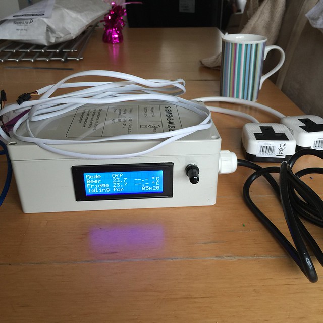
Also, here is the completed system:
3 Chamber BrewPi
THANK YOU SO MUCH! I couldn't have done it without all of your help!
Also, here is the completed system:
3 Chamber BrewPi
THANK YOU SO MUCH! I couldn't have done it without all of your help!
OP
OP
There's an intrinsic issue with the way the forums are managed that prevents editing/updating a post after some time - I think it's a month. It's a pita but we're stuck with it, otherwise I would always roll all the updates/revisions into the original post.
At some time it might be better if I start a new thread with all the updated stuff at the head, but from the example given with the RaspberryPints project, folks would still be asking questions in the old thread
Anyway, glad you're up and running...
Cheers!
At some time it might be better if I start a new thread with all the updated stuff at the head, but from the example given with the RaspberryPints project, folks would still be asking questions in the old thread
Anyway, glad you're up and running...
Cheers!
Groner
Well-Known Member
Totally know what you mean, since I struggled with the same issue in the RPints thread as well...
I'm considering putting something together for Instructables, since they are a bit more user friendly; especially one for multiple chamber set ups...
I'm considering putting something together for Instructables, since they are a bit more user friendly; especially one for multiple chamber set ups...
FuzzeWuzze
I Love DIY
There's an intrinsic issue with the way the forums are managed that prevents editing/updating a post after some time - I think it's a month. It's a pita but we're stuck with it, otherwise I would always roll all the updates/revisions into the original post.
At some time it might be better if I start a new thread with all the updated stuff at the head, but from the example given with the RaspberryPints project, folks would still be asking questions in the old thread
Anyway, glad you're up and running...
Cheers!
If your feeling up to it some time please make a page on the new Wikia i created
http://diybrewpi.wikia.com
Once i get around to finishing the rest of the main build i'll setup links to all the additional instructions you guys post.
Its for this same reason i created the Wikia because the main BrewPi thread is way too long to be of use, and i feel like people are continuing to answer the same questions over and over that have been posted 3-6 months ago.
wbarber69
Well-Known Member
- Joined
- Oct 13, 2013
- Messages
- 2,191
- Reaction score
- 263
If your feeling up to it some time please make a page on the new Wikia i created
http://diybrewpi.wikia.com
Once i get around to finishing the rest of the main build i'll setup links to all the additional instructions you guys post.
Its for this same reason i created the Wikia because the main BrewPi thread is way too long to be of use, and i feel like people are continuing to answer the same questions over and over that have been posted 3-6 months ago.
Sh!¥ some of them wait for a new page to ask what was answered yesterday.
OP
OP
Finally had a window open where my Brewpi BT minions weren't tied up and I had the free time to upgrade them with the rotary encoder and blanking FET.
Wasn't all that keen on performing this surgery because those skinny Dupont wires tend to break off at the switches when opening these little dudes up, but it had to be done eventually.
First minion anesthetized, opened up, and FET installed.

It's alive! Encoder location is a bit tight but its totally usable.

Repeat twice more and the gang is up to snuff...
Cheers!
OP
OP
Thanks, they are pretty cool li'l dudes.
The case is the same model I used for my Love TSS2 controller (which has been relegated to standby duty in case a minion were to go tits up).

Wicked cheap - when you see it up close it's pretty obvious it's made from recycled crumb.
But cramming the Uno, shield, power supply, relay module, LCD, duplex outlet, switches and LEDs - and now the encoder - in there was pretty tight. If the local e-hobby shop had a slightly larger case I would have standardized on that just for the extra wiggle room, but their next larger cheap case was like half again larger, and that just seemed too big for a temperature controller...
Cheers!
I have built a brewpi with LCD from the schematic (thanks for all your work along with Elco and co) using a '328P instead of an Arduino and connected it to the Pi serial port on the GPIO connector to save cost. I have the issues others have with the corrupt display after the relays have switched a couple of times, I have a few ideas on how to solve this so built a second to test them out. I have used the PNP transistor variant to run the backlight. On the latest schematic it shows the collector connected to the 5v rail, should this be the emitter? I don't know how I didn't spot it on the first build but did on the second!
wbarber69
Well-Known Member
- Joined
- Oct 13, 2013
- Messages
- 2,191
- Reaction score
- 263
I have built a brewpi with LCD from the schematic (thanks for all your work along with Elco and co) using a '328P instead of an Arduino and connected it to the Pi serial port on the GPIO connector to save cost. I have the issues others have with the corrupt display after the relays have switched a couple of times, I have a few ideas on how to solve this so built a second to test them out. I have used the PNP transistor variant to run the backlight. On the latest schematic it shows the collector connected to the 5v rail, should this be the emitter? I don't know how I didn't spot it on the first build but did on the second!
I imagine the pi isn't stable enough to provide enough power the 3rd party duino you're using. If you've read through all the forum you'd see that there were many mistakes on various different schematics and you are probably correct and if you go in a few pages you'll see that someone else brought it up and it has been noted. But the forum will not allow changes after a certain period of time so those schematics will always be wrong and will always be on this forum.
With the help of several others I've finally managed to get my I2C LCD working on my DIY BrewPi. I would like to share a quick "how-to" for the benefit of anyone that may be trying to add an LCD to their setup. (Using Arduino UNO)
After completing the setup recommended by FuzzeWuzze. The following steps are required to add an I2C serial LCD to your brewpi setup such as this one by SainSmart. The two files referenced in the following steps can be accessed in this repository: https://github.com/sc4z/BrewPi_I2C_LCD_Edited. Please note that the address for my LCD was found to be 0x27, if your LCD's address is different, you will require a different .hex file.
1. Connect the SDA and SCL pin outs from the LCD to the appropriate pin outs on the Arduino.
2. Connect the 5V and GND pin outs from the LCD to the "Eurostyle" connector strip junctions shown in the drawing presented by FuzzeWuzze.
3. In the brewpi web interface, reprogram your Arduino with the .hex file found in the aforementioned repository. This file was compiled by editing the initial file by Vasco, with the help of instructions made by doomlab. Because this DIY brewpi setup doesn't include a potentiometer to wake up the LCD screen, the .hex file has been edited so that the LCD backlight remains on. A reasonable compromise for this simple addition IMO.
4. As per Vasco's instructions, the onewire bus connection should be moved from the Arduino pin-out A4 to A0.
5. On your raspberry Pi, the file "pinList.py" and "pinList.pyc" located at /home/brewpi should be deleted and replaced with "pinList.py" from the aforementioned repository.
6. Run the brewpi script and have fun with your new LCD! Remember that while you're setting up your BrewPi device list, the "Beer Temp" and "Chamber Temp" functions now refer to Arduino pin A0.
**EDIT**
Thanks to AnthonyUK I was able to successfully include a rotary encoder/ push button combo:
7. Following AnthonyUK's instructions I soldered wires to each of the five connections on the rotary encoder which I ended up buying on digikey http://www.digikey.ca/product-detail/en/ACZ11BR1E-20FD1-20C/102-1768-ND/1923363. As seen in the attached image, the two black wires are connected to the same common ground as mentioned in step 2 on the "Eurostyle" connector strip. The yellow wire for the push button is connected to D7 on the Arduino, the green wire for the encoder is connected to D8 and the blue wire is connected to D9.
8. A new file has been added to the repository above. The Arduino UNO should be reprogrammed with the file named "brewpi_avr_with_encoder.hex" if you want to use an encoder. This will re-enable the backlight dimming feature.
Thanks again to everyone for their help! I'm glad to finally have everything up and running smoothly
.jpg")
.jpg")


After completing the setup recommended by FuzzeWuzze. The following steps are required to add an I2C serial LCD to your brewpi setup such as this one by SainSmart. The two files referenced in the following steps can be accessed in this repository: https://github.com/sc4z/BrewPi_I2C_LCD_Edited. Please note that the address for my LCD was found to be 0x27, if your LCD's address is different, you will require a different .hex file.
1. Connect the SDA and SCL pin outs from the LCD to the appropriate pin outs on the Arduino.
2. Connect the 5V and GND pin outs from the LCD to the "Eurostyle" connector strip junctions shown in the drawing presented by FuzzeWuzze.
3. In the brewpi web interface, reprogram your Arduino with the .hex file found in the aforementioned repository. This file was compiled by editing the initial file by Vasco, with the help of instructions made by doomlab. Because this DIY brewpi setup doesn't include a potentiometer to wake up the LCD screen, the .hex file has been edited so that the LCD backlight remains on. A reasonable compromise for this simple addition IMO.
4. As per Vasco's instructions, the onewire bus connection should be moved from the Arduino pin-out A4 to A0.
5. On your raspberry Pi, the file "pinList.py" and "pinList.pyc" located at /home/brewpi should be deleted and replaced with "pinList.py" from the aforementioned repository.
6. Run the brewpi script and have fun with your new LCD! Remember that while you're setting up your BrewPi device list, the "Beer Temp" and "Chamber Temp" functions now refer to Arduino pin A0.
**EDIT**
Thanks to AnthonyUK I was able to successfully include a rotary encoder/ push button combo:
I bought a bare rotary encoder from Amazon which has 5 connections - http://www.amazon.co.uk/dp/B00KHTLY7M/?tag=skimlinks_replacement-20
The two GNDs can share a single cable to GND and the push button goes to D7 with the left/right to D8 and D9.
7. Following AnthonyUK's instructions I soldered wires to each of the five connections on the rotary encoder which I ended up buying on digikey http://www.digikey.ca/product-detail/en/ACZ11BR1E-20FD1-20C/102-1768-ND/1923363. As seen in the attached image, the two black wires are connected to the same common ground as mentioned in step 2 on the "Eurostyle" connector strip. The yellow wire for the push button is connected to D7 on the Arduino, the green wire for the encoder is connected to D8 and the blue wire is connected to D9.
8. A new file has been added to the repository above. The Arduino UNO should be reprogrammed with the file named "brewpi_avr_with_encoder.hex" if you want to use an encoder. This will re-enable the backlight dimming feature.
Thanks again to everyone for their help! I'm glad to finally have everything up and running smoothly
Last edited by a moderator:
OP
OP
Are you saying that the special hex file for the AVR doesn't support the rotary encoder?
Cheers!
Cheers!
FuzzeWuzze
I Love DIY
Are you saying that the special hex file for the AVR doesn't support the rotary encoder?
Cheers!
Sort of unrelated but weird, i know that way back when i was first hacking this thing together and chatting with Elco reporting bugs one was this(yes i still have the image i showed him from late 2013 apparently?)

Apparently not having a rotary encoder was totally screwing up the BrewPi code they rewrote because it was expecting one and causing millions of trigger annotations that happen when you spin the rotary, so many that within a minute or two of starting a new brew the webpage wouldnt load anymore because the graph couldnt render the millions of annotations on top of eachother. I only got this 4 minute picture because i left my browser on overnight and it finally rendered some hours later.
First of all, it's very nice to hear from you both, I've really enjoyed reading all your posts while working on this project. You've been very helpful, thank-you.
As of yet I haven't been able to find a way to include a rotary encoder alongside a pre-built I2C LCD. The rotary encoder code from the original .hex file is unaltered as far as I can tell.
I'm quite glad that I haven't run into this bug! I would hypothesize that I've avoided this because a potentiometer (to control LCD dimming) is included on the SainSmart LCD I'm using. (In blue in the top right corner of the following picture)
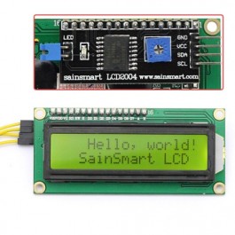
Unfortunately, adjusting this potentiometer does not reset the backlight timer. Adding a functioning potentiometer to this setup while preferably keeping it solderless would be a welcome improvement. Any ideas ?
Are you saying that the special hex file for the AVR doesn't support the rotary encoder?
Cheers!
As of yet I haven't been able to find a way to include a rotary encoder alongside a pre-built I2C LCD. The rotary encoder code from the original .hex file is unaltered as far as I can tell.
Apparently not having a rotary encoder was totally screwing up the BrewPi code they rewrote because it was expecting one and causing millions of trigger annotations that happen when you spin the rotary, so many that within a minute or two of starting a new brew the webpage wouldnt load anymore because the graph couldnt render the millions of annotations on top of eachother. I only got this 4 minute picture because i left my browser on overnight and it finally rendered some hours later.
I'm quite glad that I haven't run into this bug! I would hypothesize that I've avoided this because a potentiometer (to control LCD dimming) is included on the SainSmart LCD I'm using. (In blue in the top right corner of the following picture)
Unfortunately, adjusting this potentiometer does not reset the backlight timer. Adding a functioning potentiometer to this setup while preferably keeping it solderless would be a welcome improvement. Any ideas
?As of yet I haven't been able to find a way to include a rotary encoder alongside a pre-built I2C LCD. The rotary encoder code from the original .hex file is unaltered as far as I can tell.
The original hex from Vasco works with a rotary encoder although all you really need is a push switch to D7 to wake the display
This is what I'm using with the changes you mentioned A0, pinlist.py etc.
I'm just having an issue when the relays activate though.
I though I had solved it with a snubber but I think I'm going to have to stop using JD-VCC and power the relay separately.
The original hex from Vasco works with a rotary encoder although all you really need is a push switch to D7 to wake the display
Thanks for the advice AnthonyUK! The push button you mentioned is a nice simple upgrade. I've added another .hex file with the backlight timer function re-enabled to the repository I mentioned in my original comment so that a rotary encoder or push button can be implemented.
Would you mind explaining how you connected your fully functioning rotary encoder to your arduino alongside your I2C LCD? I'm having trouble finding resources explaining that.
I bought a bare rotary encoder from Amazon which has 5 connections - http://www.amazon.co.uk/dp/B00KHTLY7M/?tag=skimlinks_replacement-20
The two GNDs can share a single cable to GND and the push button goes to D7 with the left/right to D8 and D9.
The two GNDs can share a single cable to GND and the push button goes to D7 with the left/right to D8 and D9.
Last edited by a moderator:
wbarber69
Well-Known Member
- Joined
- Oct 13, 2013
- Messages
- 2,191
- Reaction score
- 263
First of all, it's very nice to hear from you both, I've really enjoyed reading all your posts while working on this project. You've been very helpful, thank-you.
As of yet I haven't been able to find a way to include a rotary encoder alongside a pre-built I2C LCD. The rotary encoder code from the original .hex file is unaltered as far as I can tell.
I'm quite glad that I haven't run into this bug! I would hypothesize that I've avoided this because a potentiometer (to control LCD dimming) is included on the SainSmart LCD I'm using. (In blue in the top right corner of the following picture)
Unfortunately, adjusting this potentiometer does not reset the backlight timer. Adding a functioning potentiometer to this setup while preferably keeping it solderless would be a welcome improvement. Any ideas
That's a potentiometer not a rotary encoder. The potentiometer controls the backlight intensity the rotary encoder controls the brewpi software on the arduino. And as for all that work you did. Kudos to that. But you may want to look into doomys latest. He managed to get i2c to work over software serial so you don't have to reassign the onewire pins anymore. Which is really only necessary if you already built everything to work with the usual pins. But it may also let you keep all the current features without having to move everything around.
father_jack_hackett
Member
- Joined
- Oct 8, 2015
- Messages
- 6
- Reaction score
- 1
Sorry if this has been addressed previously. Could someone tell me what the 2 diodes and the resistor are for on the LCD backlight Anode, and if I can leave them out.
OP
OP
They are for voltage drop to avoid over-driving the backlight power...
Cheers!
Cheers!
father_jack_hackett
Member
- Joined
- Oct 8, 2015
- Messages
- 6
- Reaction score
- 1
Sorry to be a pain, but my lcd module says on the spec sheet that pin 15 is +5 volts via an integrated resistor. Hence in my case do I need these extra components? I don`t understand a great deal about electronics but am more than willing to learn. Am I right in thinking that the resistor is there to cause a reduced voltage across the lcd and reduce the current flowing into it?
Are the diodes there to prevent power spikes or transient signals and why 2 of them? I've seen other schematics without these extra components. If I don't include them do I risk breaking my lcd?
I've got my brewpi working and am about to add the lcd. I've read most of the forum but its a little daunting as I have limited experience in electronics, so any advise would be gratefully received.
OP
OP
My LCD (the one I recommended in the first place) specifies a maximum voltage on the LCD backlight input (pin 15) of 4.2V.
One diode drop is generally good for around .5 volts (load dependent) and experimentation showed two drops still provided plenty of brightness (iirc the resulting voltage was around 3.4 V).
If your LCD has a 5V specification for the same voltage you can omit the diodes and the resistor...
Cheers!
One diode drop is generally good for around .5 volts (load dependent) and experimentation showed two drops still provided plenty of brightness (iirc the resulting voltage was around 3.4 V).
If your LCD has a 5V specification for the same voltage you can omit the diodes and the resistor...
Cheers!
Mikmonken
Well-Known Member
- Joined
- Mar 28, 2013
- Messages
- 423
- Reaction score
- 101
Always love coming back to this thread. I've found yet another way to scramble the display... I was trying to use my RPI to play some music simply plugging audio jack into the RPI, every time the display cycles or updates the temp it would scramble the screen. Unplug it it's back to normal so a quick fix really.
Would the audio jack leech power even if no sound was coming through it?
Would the audio jack leech power even if no sound was coming through it?
Brewski_59
https://www.facebook.com/narcosisbrew/
i bought these rotary encoders on ebay. they already have 10k resistors on them
Rotary Encoder Module Brick Sensor Development Board For Arduino #100NEW http://www.ebay.com/itm/Rotary-Enco...uino-/310702417391?roken=cUgayN&soutkn=7OSfQ4
That's the same encoder I bought. I assumed that since the 3 pull up resisters were on the board that I could just use the caps alone but it doesn't work. How did you do yours?
OP
OP
Always love coming back to this thread. I've found yet another way to scramble the display... I was trying to use my RPI to play some music simply plugging audio jack into the RPI, every time the display cycles or updates the temp it would scramble the screen. Unplug it it's back to normal so a quick fix really.
Would the audio jack leech power even if no sound was coming through it?
The Model B, B+ and Version 2 all have clamping diodes on the two audio channels, with the high side diodes referenced to 3.3V. I suppose you could induce some current flow when plugging the audio port, but it'd be really really tiny and almost over before it began.
That's the same encoder I bought. I assumed that since the 3 pull up resisters were on the board that I could just use the caps alone but it doesn't work. How did you do yours?
If there are pull-up resistors in the module, you need to add a 5V power connection from the shield to the "+" pin. That wire is only needed if the pull-ups are on the encoder...
Cheers!
Brewski_59
https://www.facebook.com/narcosisbrew/
I used the caps on the encoder switch and encoder wires. between them and ground. Without the pullups indicated on your drawing. And connected the 5vdc and ground directly to the encoder board. I'm going to try without the caps next.
Brewski_59
https://www.facebook.com/narcosisbrew/
I double checked my connections, and sure enough I had a bad connection to the ground buss. Now I have a working encoder. Which occasionally scrambles the display. But it's progress. Thanks for your help.
Brewski_59
https://www.facebook.com/narcosisbrew/
Now the led on the UNO will start to fliker rapidly during burn in. It will function normally for 15, 20 minutes. When is normal I have 5 VDC on my output. Then when it fails the voltage fluctuates, as if there is a device shorting to ground. I wonder could it be one of the caps failing, or wrong value?
wbarber69
Well-Known Member
- Joined
- Oct 13, 2013
- Messages
- 2,191
- Reaction score
- 263
That's the same encoder I bought. I assumed that since the 3 pull up resisters were on the board that I could just use the caps alone but it doesn't work. How did you do yours?
I wired the pins from the encoder straight to the arduino. havent really put one together permanently with lcd and encoder yet for permanent use.
Similar threads
- Replies
- 12
- Views
- 4K
- Replies
- 11
- Views
- 2K

Latest posts
-

-

-
 For Sale Father's Passing: Homebrew Equip. Mega Sale
- Latest: leedspointbrew
-

-

-
-

-