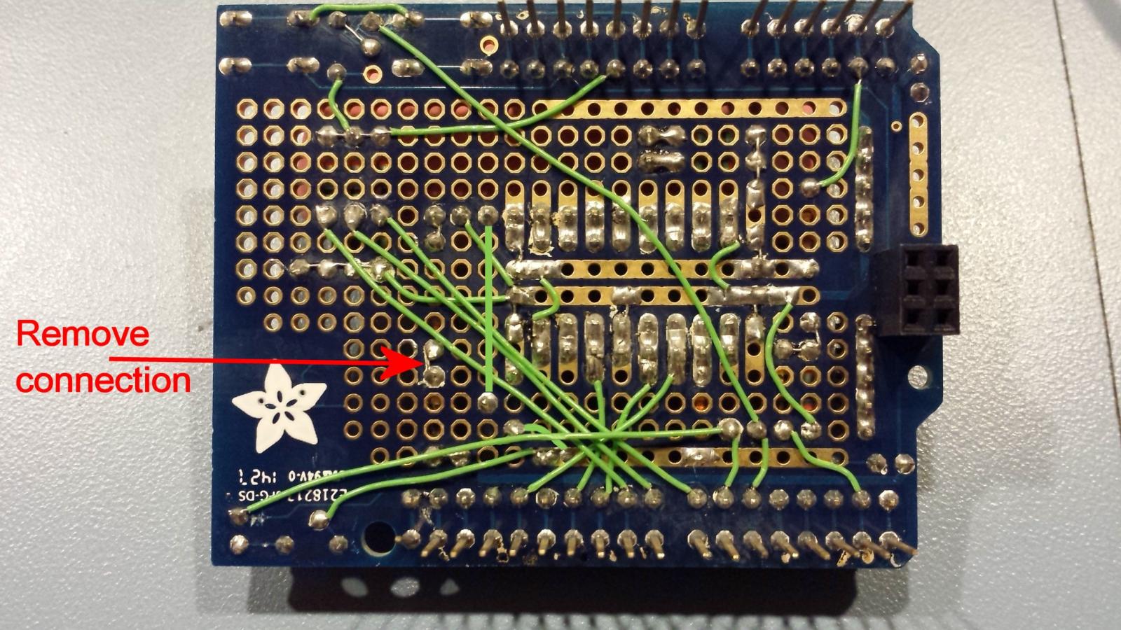
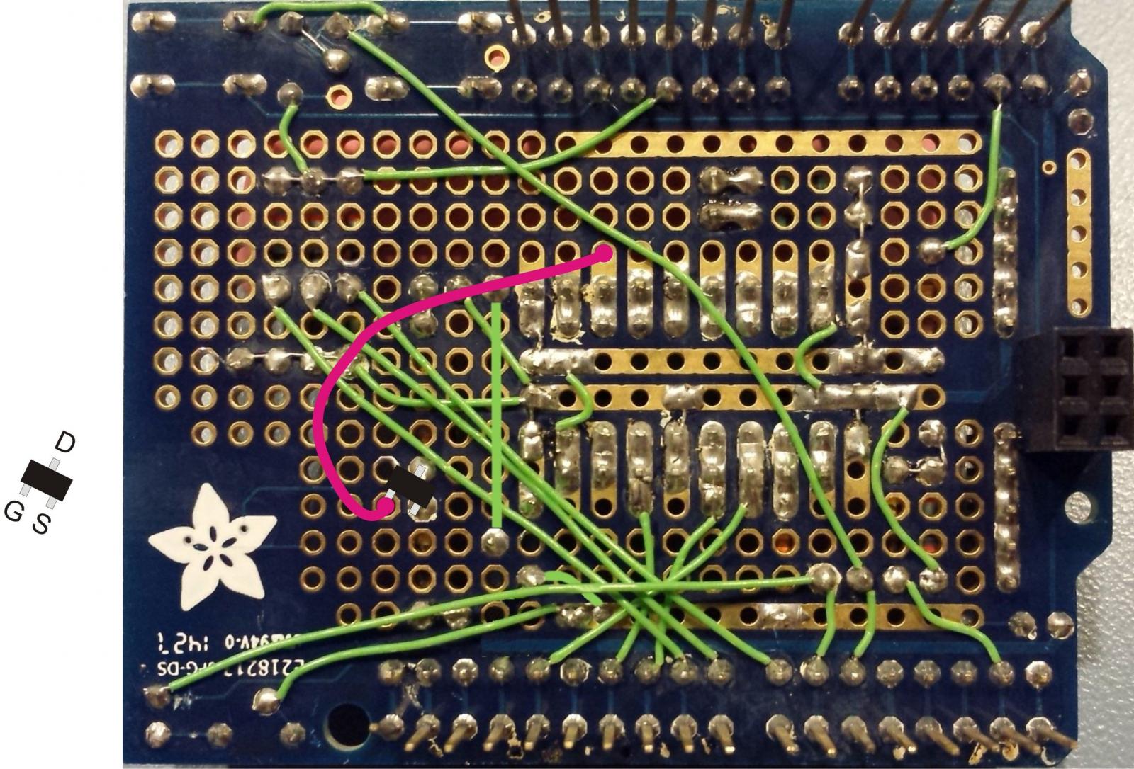
bLazem
Active Member
- Joined
- Jan 19, 2015
- Messages
- 26
- Reaction score
- 8
The backlight controller is just pin 2 from the shift register trough a 220 resistor on the gate, 5v on the collector and the emitter straight to pin 15 of the LCD.
Ah this! Didn't look so well, sorry about that.
Ok so as I said before I'm an electronics beginner and I don't know what this means by the 'gate' and I assume the 'emitter' and 'collector' are terminals on the rotary?
If you could be so kind as to add that to the latest schematic, that would be awesome.
Great thread man thanks for doing all you have done here! This project has taught me a bit about electronics and raised some interest for sure.


![Craft A Brew - Safale BE-256 Yeast - Fermentis - Belgian Ale Dry Yeast - For Belgian & Strong Ales - Ingredients for Home Brewing - Beer Making Supplies - [3 Pack]](https://m.media-amazon.com/images/I/51bcKEwQmWL._SL500_.jpg)


