BruControl: Brewery control & automation software

Homebrew Talk - Beer, Wine, Mead, & Cider Brewing Discussion Forum

Help Support Homebrew Talk - Beer, Wine, Mead, & Cider Brewing Discussion Forum:

This site may earn a commission from merchant affiliate links, including eBay, Amazon, and others.
The only question I have is: is the sensor wiring correct to the 1-wire interface board? I see sensor black to Vcc (should be ground?), sensor yellow to GND (should be DAT?), and red to DAT (should be Vcc)?

I can't tell the rest of the XLR wiring, so this is just a stab.
 
Thx. I look into it when I pull apart the probe. On cbpi yellow was gnd, black was data, and red was 5v. I guess I didn’t even match this working setup.
 
Are there pro and cons to using the vin/gnd terminals vs the dc barrel jack when using the serial connection? I found one blog suggesting to avoid the first combination.
 
Are there pro and cons to using the vin/gnd terminals vs the dc barrel jack when using the serial connection? I found one blog suggesting to avoid the first combination.
The barrel jack has a diode to prevent damaging the board if you hook up power and ground backwards, other than that they are identical.
 
Messed around and added "over the air" updates for the ESP32 tonight... will allow users to upgrade firmware over WiFi and without plugging in the USB/serial port.

That said, got a bunch more testing to do to qualify it as a ready interface... thanks to @smort for running some tests and reporting I/O functions which don't seem to be working quite yet.

does this mean the SonOff S31 OTA is coming?????
 
The S31 is based on the ESP8266. We'll have to see if we will pursue OTA for ESP8266. In all truth, its not a priority right now.

That said, I do ow you a report on hacking/programming the S31. I have had one on the bench for a while - just haven't got to it. I will try ASAP.
 
The S31 is based on the ESP8266. We'll have to see if we will pursue OTA for ESP8266. In all truth, its not a priority right now.

That said, I do ow you a report on hacking/programming the S31. I have had one on the bench for a while - just haven't got to it. I will try ASAP.
thanks

which ESP32 dev board exactly?

https://www.ebay.com/i/123231433219?chn=ps

https://www.amazon.com/dp/B0718T232Z/?tag=skimlinks_replacement-20

https://www.mouser.com/ProductDetai...pdFZnaMqxueLeBiQI3WTJSJkImVvUF2IaAjBpEALw_wcB
 
Last edited by a moderator:
Update to a few posts above regarding onewire sensors:

I tested my old temp probe on a new mega with the onewire module I linked above and CORRECT wiring. It still didn’t work but my mega did not fry again. So I soldered a ds18b20 to some spare wires and hooked it up. The sensor value immediately appeared on screen! Next step... replace the other ds18b20 in the actual thermowell and then I’m ready to continue the project. Note to self be 200% sure on which wire goes where! I’ll chalk this one up to user error.
 
What is the thought on temperature sensors. It seems most people use pt100s, but the onewire seem to require less hardware, but lag.
 
Little something cooking...
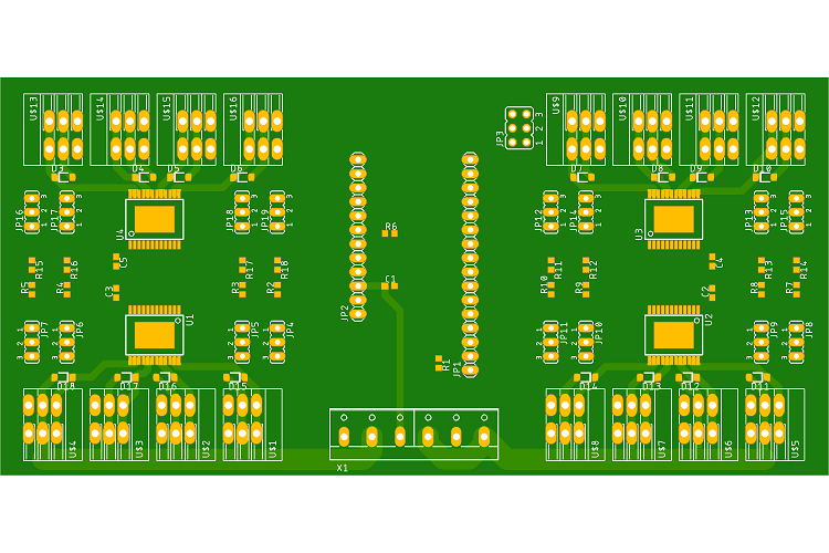
UniShield FeatherV5sch_reduced.png
 
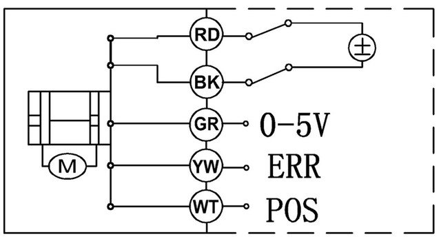
Think I might have goofed, or I'm just not understanding something. I bought the analog amplifier board from @BrunDog and a couple of 5 wire proportional valves. Wiring diagram for the valves is below.

This is embarrassing, but I can't seem to figure out how to wire up the valve to the amplifier board, which has a V+, out, and gnd for 4 devices.

Would someone care to throw me a bone on this one, or point me somewhere I can find what I'm sure is an obvious answer?
HTB1oZnKSXXXXXbzaXXXq6xXFXXXW.jpg_640x640q90.jpeg
 
First glance... but would need the model to confirm. Red and black to power and ground respectively. You can wire that through the amplifier board but would need to confirm the valve voltage requirement. 0-5V is the input, which is the output of the Amplifier. Err is error and pos is position feedback, both of which you can leave disconnected.
 
First glance... but would need the model to confirm. Red and black to power and ground respectively. You can wire that through the amplifier board but would need to confirm the valve voltage requirement. 0-5V is the input, which is the output of the Amplifier. Err is error and pos is position feedback, both of which you can leave disconnected.

Gracias amigo. What you say makes sense. What would I do if I wanted to display position info?

Model info at the link below.

https://m.aliexpress.com/item/32820...ZVf&aff_short_key=UneMJZVf&aff_platform=msite


Edit: I assume I can feed the power and ground independently from the 12v system without going through the amplifier board, if I wanted to. Is that correct?
 
Last edited:
Another newb Q. You guys see any problems using 23AWG Cat 6 wire for the 12v side of things? Biggest load is the motorized ball valves at about 2 watts.
 
Gracias amigo. What you say makes sense. What would I do if I wanted to display position info?

Model info at the link below.

https://m.aliexpress.com/item/32820...ZVf&aff_short_key=UneMJZVf&aff_platform=msite


Edit: I assume I can feed the power and ground independently from the 12v system without going through the amplifier board, if I wanted to. Is that correct?

After looking at the webpage, I am not sure if the 0-5V is the input or output. The pages says "feedback", which could easily be interpreted as an output, since it would be feedback to the controller. I suggest you contact the vendor or manufacturer for confirmation.
 
Counter Input/Flowmeter question: how does one convert/determine the rate in quarts?

Let's do some math. First you need the data from the spec sheet which says what the flow rate is. Let's suppose it provides in x quarts/pulse.

Rate is in pulse/sec. You would then multiply these to get quarts/sec. Therefore, your multiplier in BC is x. Now you probably want it in quarts/min, so multiply that times 1/60, so the multiplier in BC is x/60.

I'll bet the spec sheet does not provide the data in quarts per pulse, so let me know if you need further help, but please provide the actual spec.
 
Another newb Q. You guys see any problems using 23AWG Cat 6 wire for the 12v side of things? Biggest load is the motorized ball valves at about 2 watts.

My opnion is solid wire shouldn't be used for control systems. Its not really a biggie, so if its what you have, then use it. Vibration, temp swings, and any physical bending can cause problems for solid wiring.
 
OK HBT,

Warning... this will be a controversial post! Opinions are mine - take with a grain of salt!

One of the home brewery configurations still used in new builds is HERMs to perform mash temperature control. Conceptually, it doesn't make much sense to me: in order to heat liquid, you need to first heat other liquid. Why not just heat the liquid you want and be done? I believe in the "old days", an HLT was needed to heat water, and that HLT required a power circuit (element, SSR, contactor, PID, wiring, plugs, etc.). 30A breweries cannot run multiple elements simultaneously, and since that HLT was already there, the builder could just re-use that power circuit, hence running the mash liquid back through the HLT volume via HERMs coils.

This is of course why RIMs was created - but RIMs gets a bad reputation. If the brewer wants to run one, they need an additional power circuit to the HLT one, which adds cost, complexity, etc. That's where high power RIMs can come in... a full-power RIMs element can replace the HLT altogether and serve the function of heating strike water, maintaining mash temp, mashing out, and direct heat sparging. My personal rig uses a 5500 W element in the RIMs tube and employs a high/low relay to adjust its power between 1350 and 5500 W. It uses full power for strike water heating, mashing out, and direct heat fly-sparging and low power for mash temp steps and maintenance. Low power is used to protect the mash from the evil but mostly mythical "scorching" devil. I think that a simpler implementation of this can be used: either via software or hardware, or both.

Using software: all PIDs I am aware of have an option to limit the PID maximum output of an element. Theoretically, capping the max output of the PID to 25% during mashing will serve the same net function as a high/low relay. This can be done manually, or in BruControl, can be changed on the fly with a script command (e.g. "RIMs" MaxOutput = 25).

But what about hardware? There is no doubt that a 5500 W straight LWD (Low Wattage Density) element at 120 watts per square inch does not offer the same scorching protection as a ULWD (Ultra Low Wattage Density) element. I have personally not had any scorching in 25+ brews using this element, having applied full power to wort during mash out. But understandably many would be apprehensive.

All this said, I think a two-vessel RIMs direct heat fly-sparge system (aka 2VDS) is the best possible configuration. The hardware, space, and cost of the HLT and HERMs hardware is eliminated, accessory hardware like valves and tubing is reduced, 3 vessel benefits such as efficiency and clear wort are maintained, mash steps occur quickly and accurately independent of batch size, the brew day is faster and simplified, and control panels are no more complex than HERMs. The only complexity to implementing direct heat fly-sparging is the need to fix the incoming water rate. Here is a simple flow diagram:

View attachment 566055

I am so convinced the world needs to move past HERMs, I am putting my money where my mouth is! I have had a custom RIMs tube element made, purpose suited for this application, which we are fondly calling "QuadZilla". This is a ULWD element assembly, especially made for high-power RIMs applications in brewing. The QuadZilla is an assembled four-pack of 304 stainless steel sheathed cartridge heaters welded in a 1.5" tri-clamp cap. Each heater provides 1375 W @ 240 VAC for a total power of 5500 W and the heat density is 61 watts per square inch (9.5 W/cm^2), which is equivalent to the 5500 W ripple elements used in home brew boil kettles. Now, brewers can build a RIMs tube and run it at full power without concern of scorching. Used vertically, there is no need for RIMs flow switches or flowmeters to halt power in case of a stuck mash. In addition, they can heat strike water, mashout, and direct heat fly-sparge very easily. See more here: http://brucontrol.com/buy/quadzilla/

View attachment 566056

I have no intentions of offending lovers of HERMs here - one of the great aspects of our hobby is the different ways we approach making beer. But I strongly feel it is time to advance past the ways of old, in the same way I believe automation greatly improves our beer. I look forward to a healthy discussion and hope many others will see the benefits of a 2VDS configuration and this RIMs element. Special thanks to @augiedoggy for the general concept of cartridge heaters in RIMs applications.

Wow, was planning a brewery upgrade and I am now on a completely different trajectory than I was a week ago. I've been an eHERMS brewer for the last few years but I think I'm completely sold on a 2 vessel RIMS system and automation.

BrunDog, you have some of the biggest home brewing innovations of the last several years. Really game changing stuff! The Steam Condenser, BruControl and 2 vessel RIMS brewing are going to change my life!

I'm about to sell my 3 vessel 10G eHERMS system and roll that into a 1/2bbl 2 vessel RIMS system using full automation (and of course a steam condenser). I've been sketching out my plumbing and new brewery layout obsessively over the last several days.

In addition to the changes on the hot side, I'm moving from Speidel tanks in chest freezers to Spike Conicals with a glycol chiller. I'm really excited for the journey.

Oh yeah, and planning to dive head-first into the world of LODO.
 
Ok, as usual the documentation is suspect on these things. From other devices, I *believe* that 'F' is frequency, which is in Hz or pulses per second. Therefore, at 1 qt/min, it is 18 pulses per second. So for quart/min, multiply the rate by 1/18. To get quart/sec, multiply the rate by 1/(18*60) or 1/1080. I'll let you do the rest of the math ;-)

I also though that if measured a specified volume of water and passed it through the flowmeter at a given flow rate, while recording the total time. I would know the total pulses for a given time and volume. Then I would be able to calculate the linear multiplier for the Rate and the Total in the Counter Input, correct?

Total Multiplier = 1/total pulses
Rate Multiplier = 1/(total pulses/total time)

… I'd have to incorporate volume conversion depending on which units I tested with a which units I wanted to display.
If you want to test this imperically, you can simplify it by not worrying about flow rate. You really just need to count the number of pulses for a given volume.
 
I also though that if measured a specified volume of water and passed it through the flowmeter at a given flow rate, while recording the total time. I would know the total pulses for a given time and volume. Then I would be able to calculate the linear multiplier for the Rate and the Total in the Counter Input, correct?

Total Multiplier = 1/total pulses
Rate Multiplier = 1/(total pulses/total time)

… I'd have to incorporate volume conversion depending on which units I tested with a which units I wanted to display.

That's correct. You need to start somewhere then calibrate by making fine adjustments. The math here says there are 1080 pulses per quart (18 pulses/sec * 60 secs = 1080 pulses). So your calibration, if you want the total quart amount (not the rate) should be a multiplier of 1/1080. For the rate, it would be 60/1080. I made a mistake above.

Internet rumor on this model says the 18 is not correct though - you might try to verify.
 
Gracias amigo. What you say makes sense. What would I do if I wanted to display position info?

Model info at the link below.

https://m.aliexpress.com/item/32820...ZVf&aff_short_key=UneMJZVf&aff_platform=msite


Edit: I assume I can feed the power and ground independently from the 12v system without going through the amplifier board, if I wanted to. Is that correct?


You have this all figured out? I used the same valves on mine and used this board to send it the signal
 
Last edited by a moderator:
@BrunDog, et al— has anyone had luck with a long-ish usb cable? I’ve bought two 10 footers from amazon and they’ve both failed to communicate with the MEGA, while the short cable that shipped with the MEGA works fine.
 
EDIT— sorry that message got posted twice. I haven’t yet tried the second cable with anything other than the MEGA, and I already sent the first one back. I’ll do a quick check to make sure the cable seems otherwise fine.

Another piece of info—I got one of the MEGAs with the generic usb chip. Any chance that chip is somehow more sensitive to errors or something?

What’s the longest cable you’ve used BrunDog? 3 ft? 6?
 
Last edited:
Back
Top