• Please visit and share your knowledge at our sister communities:
  • If you have not, please join our official Homebrewing Facebook Group!

    Homebrewing Facebook Group

BruControl: Brewery control & automation software

Homebrew Talk

Help Support Homebrew Talk:

This site may earn a commission from merchant affiliate links, including eBay, Amazon, and others.
We haven’t tested Pt1000 amplifiers. I would like to tell you the firmware and software are compatible but I can’t guarantee it without verification.

Is there a reason you are contemplating PT1000 over Pt100? I don’t know of any improvement and would think the 100 ohm nominal sensors are more impervious to electrical noise.
 
Ya I am confused. Say what types of devices each are with their names and functions.

Chiller

Temp sensor (Glycol Reserve Temp) one wire sensor in the gylcol reserve tank

Valve (Recirc Loop)- 12v 2 way valve- when open this runs gylcol though the loop past theother FV valves. This keeps the loop cool, and helps with evening of gylcol reserve tank temps. (port 11)

Pump (Glycol Pump)-120v pump, it is the only pump- so it needs to be running in conjuction with any flow/cooling. (port 10)

Hysterisis (Glycol Temp Setting)-using compressor as the actor and temp sensor (Gylcol Reserve Temp) to maintain 25F in the glycol reserve tank. (port 12)

This loop is... pump out from reserve tank------>though valve(Recirc Loop)--->reserve tank in. When the fermenters are in service this loop will run 24/7 This keeps the glycol at 25F using Hysterisis (Glycol Temp Setting), ready to chill the FV's when they call.
FV1 and FV2 valves closed.


FV1

FV1 Temp sensor (FV1 Beer Temp)-one wire sensor in thermowell

FV1 Hysterisis (FV1 Set Point)-using valve 12v 2 way valve ( Port 6)

When FV1 calls for cooling, it will open its valve, close recirc Loop valve. While everything else stays the same ( Pump on, glycol maintaining temp).

When FV1 is at setpoint (using FV1 Hysterisis) it's valve closes, and recirc Loop opens. I guess it can be looked at as a 4 way valve, just diverting the constant flow somewhere at all times.


FV2

FV2 is going to be the exact same as FV1

FV2 Temp sensor (FV2 Beer Temp)-one wire sensor in thermowell

FV2 Hysterisis (FV2 Set Point)-using valve 12v 2 way valve ( Port 9)

(denote actual names)


Now FV1 and FV2 will call at the same times sometimes, which should be no big deal.
 
@augiedoggy I'm seeing similar behavior on both of my enclosures. On the brewstand controller, I occasionally lose WiFi connectivity when a pump fires, especially when an element is on. I also see temp spikes (PT100s) I need to reset the Mega when that happens. The effect of the reset is that configured valves start going back to their default state, but the pumps keep running. Fluid almost always goes places I don't want it to when that happens.

On the ferm controller, I see temp spikes (1-wire sensors) that appear to be correlated to either the circulation pump or the chamber fans turning on. There, the effect is that the spike goes across all temp sensors, and triggers the glycol chiller to cycle on.

@BrunDog sent me to a link where a guy successfully used ferrite chokes to suppress his symptoms.

Maybe you and I should compare notes and see if we can find a common thread to pull on.

I actually saw this on my new glycol controller. But it’s when a relay shuts off. THe controller loses connection until reset.
 
I actually saw this on my new glycol controller. But it’s when a relay shuts off. THe controller loses connection until reset.

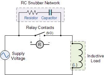
@Die_Beerery I'm not 100% sure on the timing of my "events." I may be spiking during shutoff cycles. I'm going to get a handful of the Auber snubbers that @augiedoggy suggested, and hook them across the COM/NC terminals of the relays for the pumps, fans, and the glycol chiller compressor. Here's how I'm going to do it:

io25.gif
 
I assume that L2L VPN(50mS latency) will work for a network connected Arduino... But will USB port redirection in RDP also work for BruControl, even if just for test environment?

I do most of my tinkering at home, on a separate testbed controller mockup, while the PC and system BruContol will control are 15 miles away at the shop, and I don't think I can have 2 instances of BruControl without an extra license.. (It may be a non-issue, but just wondering, I have a couple of the 5500 cards coming from Mouser, at the best price I have seen, $19.90)
 
@Die_Beerery I'm not 100% sure on the timing of my "events." I may be spiking during shutoff cycles. I'm going to get a handful of the Auber snubbers that @augiedoggy suggested, and hook them across the COM/NC terminals of the relays for the pumps, fans, and the glycol chiller compressor. Here's how I'm going to do it:

View attachment 577325
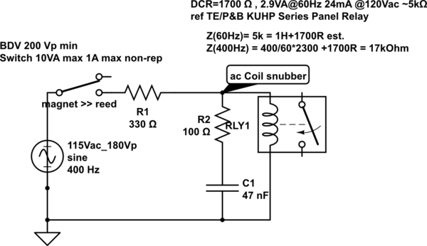
I think you want the scrubber across the coil:
(random image from google: relay coil snubber wiring )

3WJpo.png
 
First... this seems to be a common issue that is popping up... trust we will get some direction to all to remedy it. I have not witnessed it on my personal rig but I am building some test bed equipment for further evaluation. I am also talking to a new hardware partner for guidance... stay tuned.

Btw, with respect to the above snubber, they should be placed across all contacts where AC inductive loads are fed. So technically both @GParkins and @clearwaterbrewer are correct above. But note our relay coils are DC, and the relay boards we use have flyback diodes (DC “snubber” if you will) built in already.
 
@augiedoggy I'm seeing similar behavior on both of my enclosures. On the brewstand controller, I occasionally lose WiFi connectivity when a pump fires, especially when an element is on. I also see temp spikes (PT100s) I need to reset the Mega when that happens. The effect of the reset is that configured valves start going back to their default state, but the pumps keep running. Fluid almost always goes places I don't want it to when that happens.

On the ferm controller, I see temp spikes (1-wire sensors) that appear to be correlated to either the circulation pump or the chamber fans turning on. There, the effect is that the spike goes across all temp sensors, and triggers the glycol chiller to cycle on.

@BrunDog sent me to a link where a guy successfully used ferrite chokes to suppress his symptoms.

Maybe you and I should compare notes and see if we can find a common thread to pull on.
I ordered ferrite cores last week since I came across that thread in my research... I do not have them yet.
Honestly the arch suppressors from auberins worked well to eliminate the noise for the 20 mins or so I was testing. I did not get one flicker on the sensor readouts when switching the relays on and off.

I found one of my ground wires was loose going into my terminal block which was why I had no power to my ssrs.
Today I will be installing the small din rail ssrs to drive my other ssrs as well as a 5v powersupply for things like the pt 100 amplifier board which appear to be somewhat cutting out because of some poor pin socket connections from all the playing around and swapping I was doing.. I hope to get that all sorted out today.
 
Last edited:
I think you want the scrubber across the coil:
(random image from google: relay coil snubber wiring )

3WJpo.png
putting arcoss the relay contacts of the relay that powers my coils actually worked I assumed I damaged the relay board with them though when things started acting up but now I wonder if it was the poor ground connection.

I have 3 different types of snubbers, MOVs and varistors I bought though in case I needed to wire some across the actual relay contacts or coil... I'll admit I find this a bit confusing since Ive read so many conflicting opinions on all this. I may move them to the contactor coils since I would think that would be were the issue lies.. I did purchase another relay board I have to swap out as well (also optoisolated)
 
Last edited:
I actually saw this on my new glycol controller. But it’s when a relay shuts off. THe controller loses connection until reset.
yes Ive had this issue on my homebrewing rig causing my one wire sensor and some of my pt100 sensors to go whacky when my chiller or chiller pump turns on .. I have removed the one wire sensor and turned the chiller off when brewing to get around it... I have two separate control panels but the noise/ spikes still effects them both in my home brewery.
 
DC relays want the flyback diode type snubber, and yes, most relay board have them.. the AC driven ones, such as 24VAC, 120VAC or 240VAC coil contactors, will benefit.

Across the coil, and not inline with it is due to how the RC snubber works on an AC circuit: The RC circuit just is designed to ignore 50-60hz , that is they look like an open circuit (a capacitor passes high frequency, but not DC, and a larger capacitor passes lower frequencies, so a small capacitor is used), and do not interfere, but when the coil is de-energized by the opening of the switch on the left side, the coil, when de-energized, shoots out a spike of current due to the collapse of the magnetic field, and that snubber looks like a short to higher frequencies, so it dampens it. *note, if the relay powering the coil breaks contact at zero crossing, no spike is made... it may take a nearly full voltage contact break to make the energy needed to screw with the Arduino, so this may be why it is intermittent.
 
but when the coil is de-energized by the opening of the switch on the left side, the coil, when de-energized, shoots out a spike of current due to the collapse of the magnetic field, and that snubber looks like a short to higher frequencies, so it dampens it. *note, if the relay powering the coil breaks contact at zero crossing, no spike is made... it may take a nearly full voltage contact break to make the energy needed to screw with the Arduino, so this may be why it is intermittent.
Yes this is what Ive read also and it makes sense to me... although many arduino threads suggested putting the snubber across the actual relay contacts.. I'll admit in many of these cases the smaller relays werent driving a coil for a larger relay further down the line. I also have these
https://www.ebay.com/itm/MOV-V320LA40-V320LA40B-320-Volt-Littlefuse-Varistor-See-Data-Sheet-Quantity-of-5/321084946599?ssPageName=STRK:MEBIDX:IT&_trksid=p2057872.m2749.l2649

and 50 of these

https://www.ebay.com/itm/50-1uF-250VAC-250V-10-X2-Safety-Thomson-metalized-polyester-film-capacitors/290978723452?ssPageName=STRK:MEBIDX:IT&_trksid=p2057872.m2749.l2649
Would either of these be better to use across the relay coil or even main contacts?
 
Honestly the arch suppressors from auberins worked well to eliminate the noise for the 20 mins or so I was testing. I did not get one flicker on the sensor readouts when switching the relays on and off.

@augiedoggy I ordered five of the RC filters from Auber. The only place I will not have one is across the coil for the contactor that starts the glycol chiller compressor. The five filters will cover both chugger pumps attached to the brewstand enclosure, the two 4" muffin fans, the glycol circulation pump, and the glycol chiller contactor attached to the fermentation controller enclosure. I may need another one for the contactor coil, but I'm going to start with the five and get the sixth if necessary.
 
We haven’t tested Pt1000 amplifiers. I would like to tell you the firmware and software are compatible but I can’t guarantee it without verification.

Is there a reason you are contemplating PT1000 over Pt100? I don’t know of any improvement and would think the 100 ohm nominal sensors are more impervious to electrical noise.

Okay, I think then I will go ahead and order a single Pt1000 amplifier and test it out. Will report back the results for everyone.

I don't have a specific reason as to why I would use a Pt1000 over a Pt100. It just so happens that I work in a lab where we solely use Pt1000 probes due to the increase in accuracy and from a previous project I happen to already possess a few very nice Honeywell HEL-705 probes which I was hoping to utilize. I am not very familiar with arduinos measurement capabilities but I figured that since Pt1000 have a change in resistance of 3.91Ohms/C vs. the 0.391Ohms/C for a Pt100 I would probably be able to obtain more reliable and accurate measurements with the PT1000. I hear you on the shielding and noise and have already planned accordingly by using paired shielded cable. (I.e. I will setting up as a 4-wire rtd with each pair of wires shielded together and an overall shield. Is there anything else you think I could add to improve the system?
 
The fewer the connectors in between the RTD amplifier and the probe, the better. Quality cable which is as short as possible are better too. That said, if you are brewing beer, this will all give you much better results than you really need, but hey - bragging rights count!!
 
I am doing network setup on a W5500 and Mega after doing firmware install sucessfully, and I get this:

BruControl v43.F Setup 10s (y)?
BruControl v43.F Setup 9s (y)?y
Config net (y/n)? Y
MAC (##:##:##:##:##:##)?​

I do not see anything listed in the 'BruControl-Manual-v1.0-12-8-2017.pdf' manual, am I supposed to make up a mac-address and insert it? Is there really not a Burned In Address?

I hit y and enter and get:
BruControl v43.F Setup 10s (y)?
BruControl v43.F Setup 9s (y)?y
Config net (y/n)? Y
MAC (##:##:##:##:##:##)?MAC invalid
DHCP (y/n)?​

now I am locked out of it... I restarted the PC it is connected to via RDP to reset the USB, and now it does not come back up... to be continued tomorrow when I am at the shop..
 
Most W5100 boards do not come with a burned-in MAC address. What do you expect for a $19 card delivered? Most W5500 boards do have a MAC address provided on a sticker somewhere on the board.

Once you get into network config like you did, at the MAC stage, you enter the hex pairs separated by colons and hit enter. Example: AB:BC:CD:DE:EF:FA

If you have a problem, close the terminal editor, reset the MEGA, and re-enter with the terminal editor. You cannot get locked out. If there is no response after entering the configuration code, just wait a bit. It might be choking on a default network setting but should respond again shortly.
 
Understanding now you are not local to the board... I imagine that would make it tricky. But nonetheless you should be able to close and re-open the terminal editor and communicate with the board via serial comms.
 
I was able to measure the amp draw on 4 of my boil kettle ssrs.. 32ma total. I'm thinking the loose ground wire going from my shield to my ground terminal caused the overheating and my rtd amplifiers to all fail but one that works unreliable at this point. It's weird but when I plug in 12v ti the arduino the voltage regulator still gets very hot pretty quickly.. not sure how hot they should get but when feelng the back of the board it's hot but not when running off usb.. I swapped meats with a new one.. same results and 12v supply has the ground connected to same ground terminal.
 
So the 32mA is for all 4 SSR’s meaning 8 each? Are these powered simultaneously via one pin or individually via discrete pins? 32 would be too much for one pin by far.
yes and yes all on one pin they are all being turned on and off at the same time. sorry if I wasnt clear but thats what I meant by controlling groups of ssrs in post #686..

This is good to know because I only know of the max limit on the arduino I dont recall seeing limits on each pin. now I need to find an ssr that will switch such a small load since the din rail ssr I bought only works with 24 AC and I missed that when I purchased them.

My arduino gets hot even when all of the ssrs are off though and everything is disconnected or shut off so I'm assuming the voltage regulators just get hot on these.
 
Last edited:
Yes the regulator will get warm with 12 V input. It is soldered to the PC board as a heat sink but if you would like more cooling add a stick-on mini heat sink.

You can use a darlington array to drive higher loads. I will look one up for you.
 
Most W5100 boards do not come with a burned-in MAC address. What do you expect for a $19 card delivered? Most W5500 boards do have a MAC address provided on a sticker somewhere on the board.

Once you get into network config like you did, at the MAC stage, you enter the hex pairs separated by colons and hit enter. Example: AB:BC:CD:DE:EF:FA

If you have a problem, close the terminal editor, reset the MEGA, and re-enter with the terminal editor. You cannot get locked out. If there is no response after entering the configuration code, just wait a bit. It might be choking on a default network setting but should respond again shortly.

OK, Rebooting the PC must have had some of the long updates, a couple hours later I could RDP back in.. Problem one fixed... I was able to get back in to the device with InterfaceSetup.bat, problem two solved... This W5500 does not have a MAC, or a sticker, and I did not want to screw stuff up before I knew exactly what the device had... I took my PC MAC and incremented it by one to make sure I did not step on any reserved MAC address space and created a static binding and host mapping in my Cisco router. I am now able to ping the device from the network. Problem 3 now solved also. I think a couple lines added to the next version of the manual would help a lot of folks.
 
Last edited by a moderator:
OK, Rebooting the PC must have had some of the long updates, a couple hours later I could RDP back in.. Problem one fixed... I was able to get back in to the device with InterfaceSetup.bat, problem two solved... This W5500 does not have a MAC, or a sticker, and I did not want to screw stuff up before I knew exactly what the device had... I took my PC MAC and incremented it by one to make sure I did not step on any reserved MAC address space and created a static binding and host mapping in my Cisco router. I am now able to ping the device from the network. Problem 3 now solved also. I think a couple lines added to the next version of the manual would help a lot of folks.

I thought we addressed this in the appendix but I will look. Always a work in progress and I appreciate the feedback!

I am surprised the W5500 board did not come with a MAC listed. The W5100’s are typically Chinese knock-offs so they certainly do not pay for the reservations. Maybe the same is starting with the W5500’s.

and I assume that mouser would sell genuine...

Also, while in the manual, maybe update the virtual addresses being numbered 200+ for 1-wire, it is not in there..

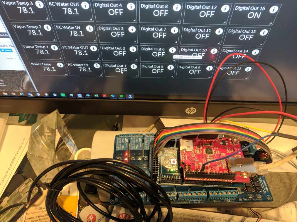
I am chugging away and have relay board and one-wire working, and it is nearly ready to install.
IMG_20180704_104721s.jpg
 
Back
Top