I decided to start building a brewing system

Homebrew Talk - Beer, Wine, Mead, & Cider Brewing Discussion Forum

Help Support Homebrew Talk - Beer, Wine, Mead, & Cider Brewing Discussion Forum:

This site may earn a commission from merchant affiliate links, including eBay, Amazon, and others.
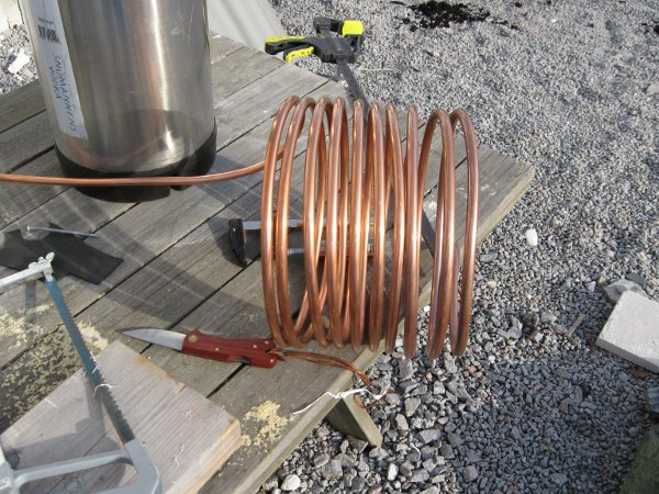
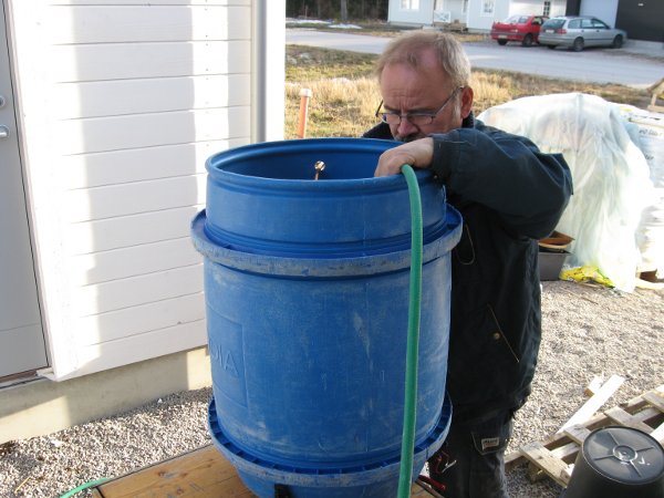
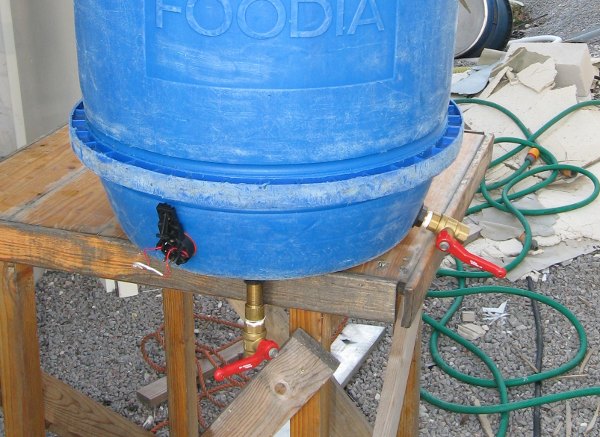
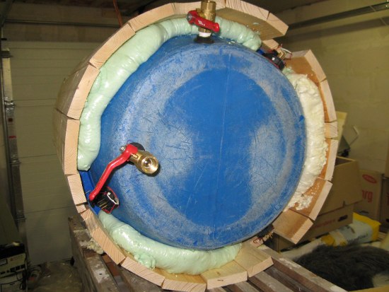
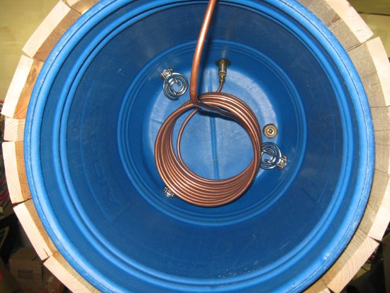
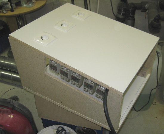
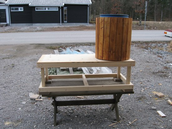
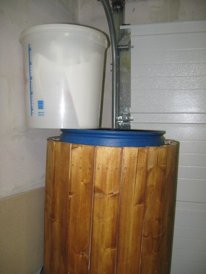
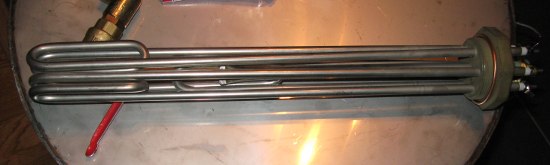
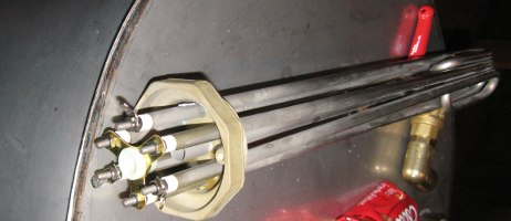
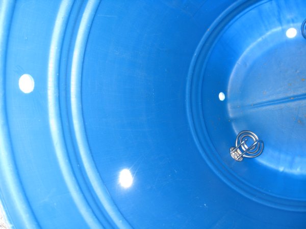
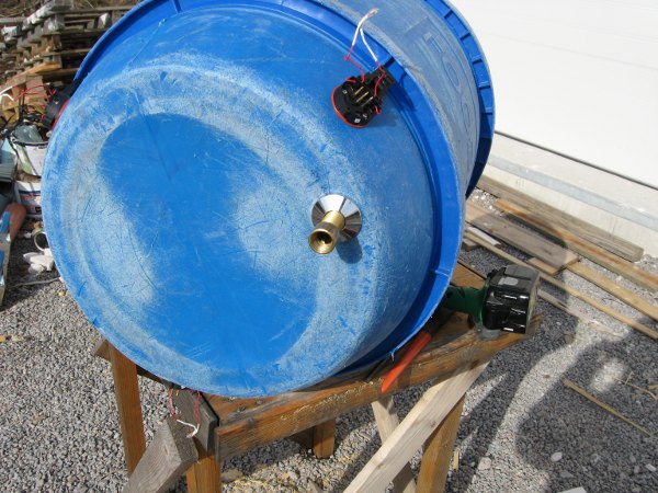
Drilled some holes in the HLT today. One for the water outlet (bottom) and two for the heat exchanging coil.
holes.JPG


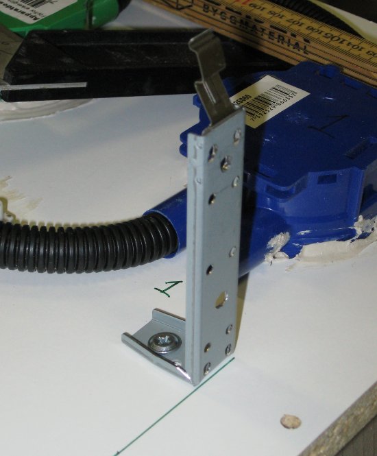
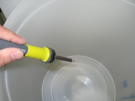
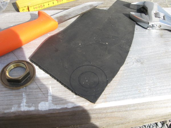
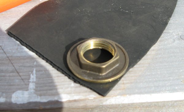
Had to create som custom seals and here you can see the procedure to do that. The black mat is some woven thing that my plumber said would be the best since I will be working with stuff that is intended to drink and that can stand the heat.

seal_pic_1.JPG


seal_pic_2.JPG
 
Here you can see the water outlet mounted.

hlt_draget_botten.JPG


Time to start with the heat exchanging coil.

Showing a safe and fast way to peal that plastic of this type of copper tubing. (Called Prisol tubings in Sweden).
Note: Move knife towards you and hold both thumbs behind the blade. (Good advice that I got from the plumber, would have cut my thumbs on multiple occations if I wouldn't have listened. :)

pipe_pealing.JPG


Used a cornelius keg to get a nice coil.

heatexchangecoil.jpg
 
When things were assembled, it was time to see that the tun was working properly (i.e. no leaks)

filling.JPG


I let my plumber do the inspections. ;)

plumber_inspection.JPG


Bottom - Water Outlet

To the right - in to the heat exchanger

valves.JPG
 
So you figure 20 kWh's? Thats not so bad then.

When do you think you will be able to brew your first beer on this system?

Well I think that I will be able to brew some first brews on the system within 2 weeks (unless I have to work a lot overtime).
But brewing with the system when it's "done"...wonder if that will ever happen, guess I can find things to improve forever :)
 
Well I think that I will be able to brew some first brews on the system within 2 weeks (unless I have to work a lot overtime).
But brewing with the system when it's "done"...wonder if that will ever happen, guess I can find things to improve forever :)

Your system is nver done till they've foreclosed on the second house.
 
Spent a few hours yesterday and today to start building on the "low tech" parts for the control panel. Stuff like wiring and thinking. :)
Hardest part was to find something to mount everything on. But after a while I remembered that we had some leftover shelves for an IKEA wardrobe.

I don't know how much sense these pictures make for you north american guys, as this uses 3x400 VAC + N + Ground.
(I guess the north american layout would be 3x220 VAC +N+G?)

kontroll_panel_baksida_2.JPG

This is how far I got yesterday until it was time to go to bed.
The red plug is the CEE plug i.e. where the power gets in.

kontroll_panel_baksida_3.JPG

Today I connected it together.
The way I have connected it, I will use 230V for each wall-outlet (i.e. one phase + N)

As you can see, I am yet to mount the Solid State Relays that will turn on/off power to the wall-outlets
kontroll_panel_framsida.JPG

This is what the front looks like....not so much right now, but give it time. I am sure it eventually will look like something from moon base alpha.
 
This is the circulation pump that I got (for Free!!!!!). It has been used for circulating hot water.

cirkpump.JPG


Edit: it should be able to circulate approximately 8 gallons per minute when running on full speed.
 
Can you control fluid flow with that pump?

Yes, according to the plumber, there are two ways of doing that.

1. Regulate on the output using a valve e.g. something similar to this
3004_1.jpg


2. Do speed regulation with a dimmer (but then it needs to be a special type of dimmer that can manipulate the frequency don't know the name for that type of dimmer)
 
2. Do speed regulation with a dimmer (but then it needs to be a special type of dimmer that can manipulate the frequency don't know the name for that type of dimmer)

Actually...when I searched to find the specs, I don't think that I will dare to do the second alternative, as I found out that the pump's "new retail price" is around $300, so then I'd rather stick with the safer valve regulation (i.e. simulating pumping water to 1 or 2 floors above you)
 
Today I decided to mount a few ribs on the HLT to figure out solutions for the "hard ribs" i.e. where the heating elements and valves are.

hlt_wood.JPG


After that it was time to tackle another problem, how to mount the SSR:s as I want to have them on the left hand side in the control panel. (Will have a window on the side so I easily can see if there are any problems with the SSR:s - and besides that...what's the point of having LED indicators on the SSR:s if you wouldn't be able to see them glow. ;) )

My fiancee suggested that I somehow should use the old harddisk brackets that we threw away the other day. Said and done

This is how I transformed harddisk brackets (right) to SSR brackets (left) with some cutting and bending.

ssr_brackets.JPG


... and drilling ...

ssr_brackets_drill.JPG
 
Time to mount the SSR brackets.

ssr_brackets_mount_1.JPG


And this out of focus picture show how the SSR:s will be placed.

ssr_brackets_mount_2.JPG


Here all SSR brackets are mounted.

ssr_brackets_mount_3.JPG


From the right:
HLT1, HLRT, HLT3 - for the heating elements in the HLT
RB - Rolling Boil
BTB1, BTB2 - Bring to Boil (these will operate on the same output from the controller)

Couldn't find any suitable screws so I made a temporary SSR mount using straps.

ssr_brackets_mount_4.JPG
 
It's great to see the progress...keep 'em comin'!!

Thanks :)
And the weather forecast is indicating rain and wind this weekend, so "unfortunatly" I will not be able to work on my garage...so instead I will have some extra time to work on the brewing system. *yay*
 
Yay...bad weather today so I spent some time in the garage, working with my brewing system.

I worked mainly with the HLT today, putting the wood ribs on.

hlt_PU.JPG

Also insulated below the roller ring. Every Watt saved by insulation will be a Watt spent on heating the water instead.

View inside the the HLT.

hlt_HE.JPG


The result after sanding the wood (a very dusty activity).

smooth_hlt.JPG


Close-up of the power connector to a heating element in the HLT
power_HLT.JPG
 
Decided to finish the day with some wood work for the control panel.
On top - below the outlets - is where the the displays, buttons, etc will go.
89_karmacontrol_panel.JPG
 
Are you going to be putting heat sinks on the SSRs?

Kal

+1. If you're passing 25A through a 40A SSR, you'll be generating some heat. I've seen hot SSRs stick closed... i.e. control voltage is cut, but the load stays energized due to it being too hot. The 40A SSR I have says to use a heatsink if the load is over 10A. You could probably mount all of the SSRs on a single heat sink easily enough.

btw, your accent reminds me of a friend of mine in Stockholm... and SSR stands for solid state relay. Keep up the good work! You obviously know what you're doing.
 
Are you going to be putting heat sinks on the SSRs?

Kal

...and...

+1. If you're passing 25A through a 40A SSR, you'll be generating some heat. I've seen hot SSRs stick closed... i.e. control voltage is cut, but the load stays energized due to it being too hot. The 40A SSR I have says to use a heatsink if the load is over 10A. You could probably mount all of the SSRs on a single heat sink easily enough.

btw, your accent reminds me of a friend of mine in Stockholm... and SSR stands for solid state relay. Keep up the good work! You obviously know what you're doing.

With the setup that I have I will never push more than (2000W/230VAC) 9 A through the SSR:s so I think that I am ok without heat sinks. I have however thought about cooling the SSR:s in case I would experience them getting hot.
In that case I will first try with mounting a fan blowing through the SSR:s. If that wouldn't work then it will be a combination of heat sinks and fan.
When I started building the control panel box, then I decided to make it in a way that hot air will escape using "mother nature" i.e. hot air raises.

Btw...have I typed/said anything else than Solid State Relay for the SSR acronym? If so, pls tell me where so I can correct. :)
(Working for a company where we use A LOT of acronyms and many which are starting with 'S' so it might have been that I have typed/said something wrong somewhere)
 
... As you can see, I am yet to mount the Single State Relays that will turn on/off power to the wall-outlets ...

Seemed like I had read that a few times throughout the thread... wasn't trying to nitpick. Your command of English is much better than my command of Swedish :). I have a few Swedish friends, and have to rely on Google Translate often to figure out what they are saying on facebook :).

Oh, and I agree if you're only running 9a through those SSRs, you probably won't need a heat sink.

Keep up the good work!
 
Seemed like I had read that a few times throughout the thread... wasn't trying to nitpick.

No worries, I want my thread to be as correct as possible - at least when it comes to the technical parts. :)


I read through my postings and...you are right. Somehow I have written 'Single State Relays' on two occations.
Which is a bit funny. I mean, what would the point be with a 'single state' relay...as that would defeat the purpose of having a relay in the first place. :)
 
Started the day by getting some stuff at the local lumberyard.
After that I begun building a cart for the HLT and MLT. Want them to be on wheels so I can move them around when doing cleaning etc.

stand_01.JPG


This is where I will mount the wheels

stand_02.JPG


With my framing nailer it's just *bang bang bang* and you're done.

stand_03.JPG


My MLT posing on the new cart.
stand_04.JPG
 
Finished the day by varnishing the HLT.

hlt_color.JPG


I also accidently knocked the can of varnish over, made a big mess in the garage. :mad:
 
Awesome work, the size of everything is impressive.

Thank you. I went with the philosophy that you can brew small batches just as easy as big batches with a big system. (But primarely the size pretty much was set when I found the add for the tuns)

I don't have that much left to do until the brewing system is in operational state - which means that I better start clearing out the garage so I can put tiling the floor and the walls in the designated brewery section. (cleaning and tiling don't reach high on my 'top ten things I like to do'-list)

But...spring is coming so I need to get into the beer production.
 
Continued with some work on the brew-cart.

Put a second shelf on the cart (bottom one)
stand_05.JPG


And as I want an easy to clean surface on the top I bought a fairly cheep laminated floor that had a walnut/zebrano look.
Found a left-over tube of construction glue that I used. That glue is so strong that I bet you could use it to make planets stick to each other.
And naturally the tube burst mid-gluing so by the time I was finished with the "flooring" of the cart the fumes had made me a bit dizzy so I stopped working for today.

stand_06.JPG
 
I have spent some time thinking about how I should solve the grain bed filtration in the MLT. Have thought about having a SS screen false bottom, manifolds, filter bags etc. It's not unlikely that I will decide to take any of those paths later on, but for now I have decided on a simpler way.

I will use an old fermentation bucket.
When comparing the size, you can see that the 8 gallon fermentation bucket easily will fit into the MLT.

tun_vs_tun.JPG


I wasn't too exited about drilling hundreds of holes, so I thought about an alternative solution...using a soldering pen. Even if I probably will need to replace the tip (although it didn't look too bad afterwards) I see some benefits with this method. You get smooth edges when you melt the plastic. When you drill in plastic you often need to sand/scrup small plastic pieces afterwards.
Since I did it from the inside, each hole also was formed like a funnel.

false_bottom_tun_01.JPG


It does however smell quite bad when doing it so the door should probably be open for ventilation.

false_bottom_tun_02.JPG

I think that I will use a filtering bag in combination with this false bottom tun-in-tun.


I am also evaluating doing a hop filter sphere that will look kind of like this
hop_sphere.JPG
 
how much wasted space will there be with the bucket in the MLT? Why not just make a manifold? I think the bucket in bucket method has been proven less effective than a manifold or braid.
 
how much wasted space will there be with the bucket in the MLT? Why not just make a manifold? I think the bucket in bucket method has been proven less effective than a manifold or braid.

Well if it will show that the bucke in bucket method, with filter bag would be less efficient - then I can always change.

I can however not see the logic reason why it would be less efficient as the grain-and-water contact according to my logic would be the main contributer for efficiency. Or?

Maybe someone that has tried both methods could spread some light on this issue?
 
Took a trip to a plumber supply shop today and bought the heating element(s) for the boiler

3x2000 W

6kw_1.JPG


6kw_2.JPG
 
Curious about scorching as well, I've heard only use "low density" elements for the brew kettle. Have you heard anything about that?
 
Umm, I presonally think these look to be about 12" long not counting the foldover... that should work out to a very reasonable amount of power per square inch. North American 2000w high density elements are about 7 inches with no foldover.

I think he should be fine. Additionally in one of the other threads, there have been reports of zero issues using high density elements and scorching, even on a very pale pilsner. That has been real world experience, not conjecture.
 
Back
Top