• Please visit and share your knowledge at our sister communities:
  • If you have not, please join our official Homebrewing Facebook Group!

    Homebrewing Facebook Group

I decided to start building a brewing system

Homebrew Talk

Help Support Homebrew Talk:

This site may earn a commission from merchant affiliate links, including eBay, Amazon, and others.
Today my 10 Solid State Relays arrived, so tomorrow I hope to be able to do the first "automation" test with the relays connected to the controller.
 
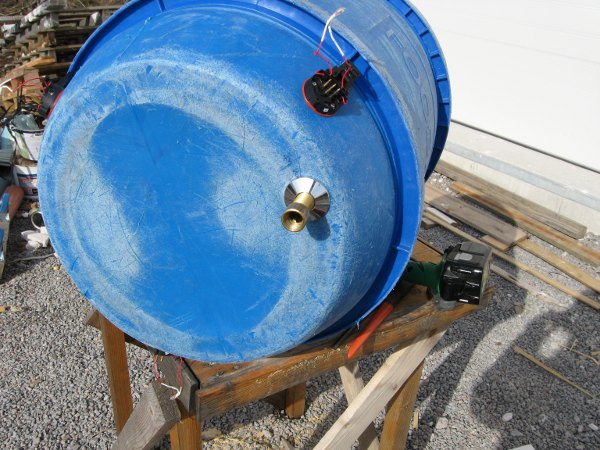
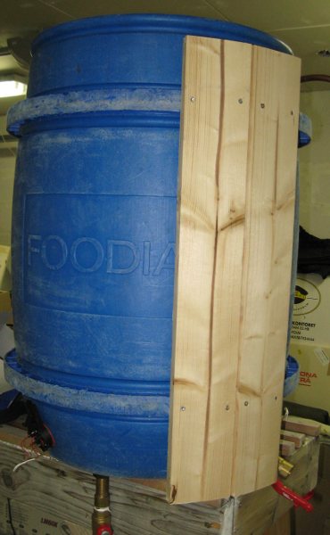
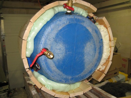
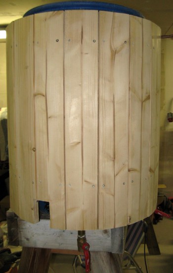
That's sweet man. I'm working om my 55 gal MLT and had the idea of wood boards around it. Now seeing yours I may do that. Looks great. :mug:

Thank you.
I wanted to hide those blue tuns and get a retro look as well.
 
First of all...had a deadline at work so with all the overtime, I have not been able to put in as much time as I would have wanted to work with my brewing system.

Have done some work on the controller. I was planning to do the temperature probing on a single bus, but when trying to use the libraries that I found, supporting this setup for the DS1820 temperature sensor I discovered that the library in itself took almost all the available memory of the PIC that I am using.

Instead I will use one port for each DS1820 that I need...no problem as I have plenty of ports available.

Next weekend will be a kodak weekend when it comes to the brewing system. My soon to be in-laws are visiting, my fiancee's dad is a plumber. He will bring stuff like copper pipings, SS pipings, circulation pump(s), valves, fittings etc etc.
Best of all.....Freebies!!!!! :mug:
 
I made a demo video where I show the temperature controller (that I now call KarmaControl)
Video quality is quite bad - and somehow my accent became Swedish in the upload...strange ;)

[ame=http://www.youtube.com/watch?v=f5JgpfDiv3k]YouTube - Temperature regulation unit for beer brewing[/ame]

Edit: Forgot to add the pin layout.

' PORTA - DS18S20 multiple inputs
' RA0 - HLT DS18S20
' RA1 - MLT DS18S20
' RA2 - Heat Exchange In DS18S20
' RA3 - Heat Exchange Out DS18S20
' RA4 - Boiler - DS18S20
' RA5 - CFC In (warm side) DS18S20
' RA6 - CFC Out (cold side) DS18S20
' RA7 - Room temperature DS18S20
'
' PORTB - Outputs triggered by program
' RB0 - HLT Heating element A
' RB1 - HLT Heating element B
' RB2 - HLT Heating element C
' RB3 - Boiler - elements for bringing to boil
' RB4 - Boiler - element(s) for keeping a rolling boil
' RB5 - To be determined
' RB6 - To be determined
' RB7 - Circulationpump operative
'
' PORT C - Inputs used for buttons etc
' RC0 - BUTTON <OK>
' RC1 - BUTTON <+> <C>(element for settings) <switch menu + >
' RC2 - BUTTON <-> <B>(element for settings) <switch menu - >
' RC3 - BUTTON <ret>-return/back <A>(element for settings) <settings menu>
' RC4 - Spare
' RC5 - Spare
' RC6 - Spare
' RC7 - Spare
'
' PORTD - Used for LCD display
' PORTE - Not used
 
Ok.
Now the in-laws have arrived and I got a couple of bags with goodies.

skaladekopplingar.jpg


As promised...a Kodak moment ;)
 
Freebies!
Looks like a great plan. I like my propane setup but you guys with the processor controlled rigs do appeal to my inner geek. I'll be watching this thread for sure
 
Drilled some holes in the HLT today. One for the water outlet (bottom) and two for the heat exchanging coil.
holes.JPG


Had to create som custom seals and here you can see the procedure to do that. The black mat is some woven thing that my plumber said would be the best since I will be working with stuff that is intended to drink and that can stand the heat.

seal_pic_1.JPG


seal_pic_2.JPG
 
Here you can see the water outlet mounted.

hlt_draget_botten.JPG


Time to start with the heat exchanging coil.

Showing a safe and fast way to peal that plastic of this type of copper tubing. (Called Prisol tubings in Sweden).
Note: Move knife towards you and hold both thumbs behind the blade. (Good advice that I got from the plumber, would have cut my thumbs on multiple occations if I wouldn't have listened. :)

pipe_pealing.JPG


Used a cornelius keg to get a nice coil.

heatexchangecoil.jpg
 
When things were assembled, it was time to see that the tun was working properly (i.e. no leaks)

filling.JPG


I let my plumber do the inspections. ;)

plumber_inspection.JPG


Bottom - Water Outlet

To the right - in to the heat exchanger

valves.JPG
 
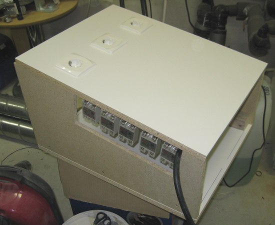
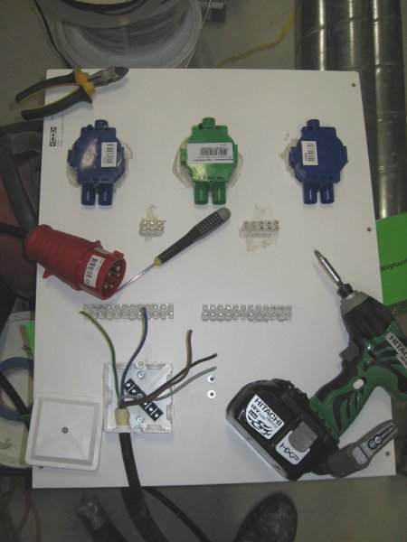
So you figure 20 kWh's? Thats not so bad then.

When do you think you will be able to brew your first beer on this system?

Well I think that I will be able to brew some first brews on the system within 2 weeks (unless I have to work a lot overtime).
But brewing with the system when it's "done"...wonder if that will ever happen, guess I can find things to improve forever :)
 
Well I think that I will be able to brew some first brews on the system within 2 weeks (unless I have to work a lot overtime).
But brewing with the system when it's "done"...wonder if that will ever happen, guess I can find things to improve forever :)

Your system is nver done till they've foreclosed on the second house.
 
Spent a few hours yesterday and today to start building on the "low tech" parts for the control panel. Stuff like wiring and thinking. :)
Hardest part was to find something to mount everything on. But after a while I remembered that we had some leftover shelves for an IKEA wardrobe.

I don't know how much sense these pictures make for you north american guys, as this uses 3x400 VAC + N + Ground.
(I guess the north american layout would be 3x220 VAC +N+G?)

kontroll_panel_baksida_2.JPG

This is how far I got yesterday until it was time to go to bed.
The red plug is the CEE plug i.e. where the power gets in.

kontroll_panel_baksida_3.JPG

Today I connected it together.
The way I have connected it, I will use 230V for each wall-outlet (i.e. one phase + N)

As you can see, I am yet to mount the Solid State Relays that will turn on/off power to the wall-outlets
kontroll_panel_framsida.JPG

This is what the front looks like....not so much right now, but give it time. I am sure it eventually will look like something from moon base alpha.
 
This is the circulation pump that I got (for Free!!!!!). It has been used for circulating hot water.

cirkpump.JPG


Edit: it should be able to circulate approximately 8 gallons per minute when running on full speed.
 
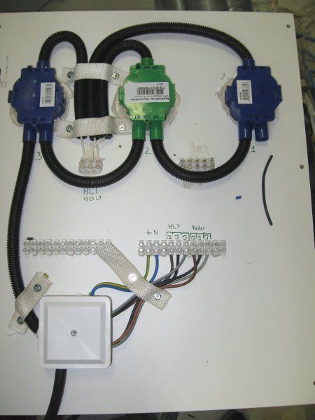
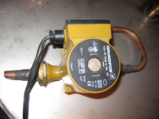
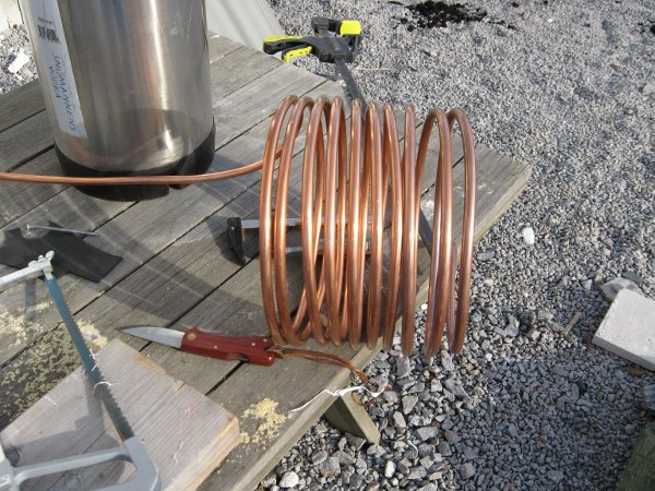
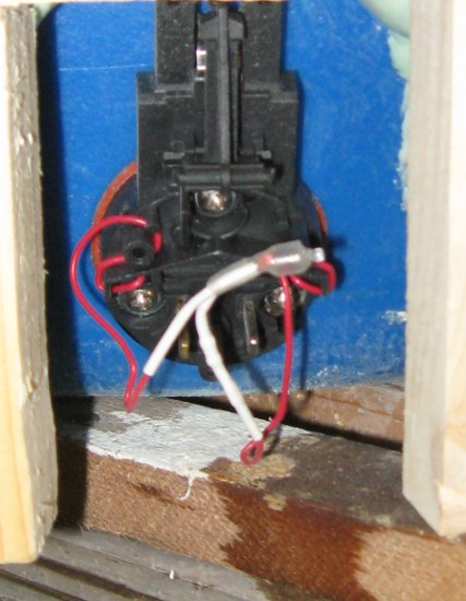
Can you control fluid flow with that pump?

Yes, according to the plumber, there are two ways of doing that.

1. Regulate on the output using a valve e.g. something similar to this
3004_1.jpg


2. Do speed regulation with a dimmer (but then it needs to be a special type of dimmer that can manipulate the frequency don't know the name for that type of dimmer)
 
2. Do speed regulation with a dimmer (but then it needs to be a special type of dimmer that can manipulate the frequency don't know the name for that type of dimmer)

Actually...when I searched to find the specs, I don't think that I will dare to do the second alternative, as I found out that the pump's "new retail price" is around $300, so then I'd rather stick with the safer valve regulation (i.e. simulating pumping water to 1 or 2 floors above you)
 
Today I decided to mount a few ribs on the HLT to figure out solutions for the "hard ribs" i.e. where the heating elements and valves are.

hlt_wood.JPG


After that it was time to tackle another problem, how to mount the SSR:s as I want to have them on the left hand side in the control panel. (Will have a window on the side so I easily can see if there are any problems with the SSR:s - and besides that...what's the point of having LED indicators on the SSR:s if you wouldn't be able to see them glow. ;) )

My fiancee suggested that I somehow should use the old harddisk brackets that we threw away the other day. Said and done

This is how I transformed harddisk brackets (right) to SSR brackets (left) with some cutting and bending.

ssr_brackets.JPG


... and drilling ...

ssr_brackets_drill.JPG
 
Time to mount the SSR brackets.

ssr_brackets_mount_1.JPG


And this out of focus picture show how the SSR:s will be placed.

ssr_brackets_mount_2.JPG


Here all SSR brackets are mounted.

ssr_brackets_mount_3.JPG


From the right:
HLT1, HLRT, HLT3 - for the heating elements in the HLT
RB - Rolling Boil
BTB1, BTB2 - Bring to Boil (these will operate on the same output from the controller)

Couldn't find any suitable screws so I made a temporary SSR mount using straps.

ssr_brackets_mount_4.JPG
 
It's great to see the progress...keep 'em comin'!!

Thanks :)
And the weather forecast is indicating rain and wind this weekend, so "unfortunatly" I will not be able to work on my garage...so instead I will have some extra time to work on the brewing system. *yay*
 
Yay...bad weather today so I spent some time in the garage, working with my brewing system.

I worked mainly with the HLT today, putting the wood ribs on.

hlt_PU.JPG

Also insulated below the roller ring. Every Watt saved by insulation will be a Watt spent on heating the water instead.

View inside the the HLT.

hlt_HE.JPG


The result after sanding the wood (a very dusty activity).

smooth_hlt.JPG


Close-up of the power connector to a heating element in the HLT
power_HLT.JPG
 
Decided to finish the day with some wood work for the control panel.
On top - below the outlets - is where the the displays, buttons, etc will go.
89_karmacontrol_panel.JPG
 

Latest posts

Back
Top