kzimmer0817
Well-Known Member
Thanks for the help so far.
I confess that I'm doing this research a little early. I've only done 2 brews thus far: NB's Nut Brown Ale (extract + specialty grain) and NB's American Wheat (extract only). I have two more extract + specialty grain kits to brew before I move to all-grain. I've decided to do BIAB; I've already spent a lot of time reading thru the BIABrewer forum. In fact, it was thughes's E-BIAB build on that site that convinced me to do this myself. He referred me to the HBT forum. His HBT thread is:
https://www.homebrewtalk.com/f170/single-vessel-biab-electric-build-275238/
I plan to follow Todd's build pretty closely using a single-kettle BIAB with a pump recirculation to help maintain mash temps.
1 220/240V heating element
1 pump for recirculating from the bottom of the kettle back to the top
1 temp probe in the kettle
I will likely use a Spa Panel for GFCI protection.
Todd did not post a schematic for his build, but said that he followed principle he gleaned from Kal's site with much help from HBT forum and, especially, P-J. The two schematics I've found that appear to be the closest to what I would need are voltin's and johnodon's. These are very similar, but not identical to each other.
Link to johnodon's schematic:
https://www.homebrewtalk.com/f170/my-official-e-biab-build-thread-269164/#post3263178
Link to voltin's build
https://www.homebrewtalk.com/f170/yet-another-ebiab-build-282235/
Voltin's control panel controls are closer to what I want, but I'm having a little difficulty understanding some of his schematic. As in my other posts, questions come first:
1. Power switches for "Main", "PID" or having both.
Voltin includes a "Main Power" button. If this is "OFF" the entire system is off. There is no current at the element - even if the "Element" switch is ON. The pump will not operate, either.
Johnodon doesn't have a "Main Power", but has a "PID" button as do several other builders. This appears to cut power to the PID, but the control box is still hot. With the johnodon's PID switch OFF, he can still operate his pump. Even with the PID switch OFF, there is still a hot leg at the element if he forgets to turn OFF his "Element" switch. At least on a 3-vessel system, I can see why one might want to turn off the PID and the Element while being able to use the pump(s) during clean-up (flushing all the tubes with clear water, etc.).
I'm leaning towards having switches for "Main", "Element", and "Pump" as Voltin. Is there a particular advantage to having a switch to turn ON/OFF the PID?
2. Alarm: It appears that folks tend to have a (1) buzzer for the alarm, (2) a switch to turn ON/OFF the alarm, and (3) a light to indicate that the alarm circuit has been activated. I'm assuming that the alarm is wired to the PID to signal that the desired temp has been reached. IOW, is the parameter for the alarm set in thru the PID? Does one also turn the alarm ON/OFF from the PID itself? Is there any problem with the PID trying to announce an alarm, yet the Alarm switch on the panel is OFF, so essentially, there's no alarm going off?
3. I guess I should have one of those big EPO buttons on top - whichever kind is best.
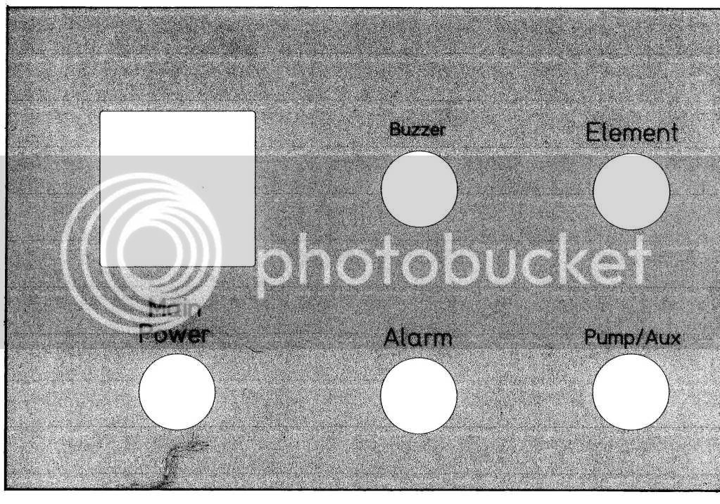
4. Depending upon your recommendations regarding my question about having a choice of either PID and PWM control in the same box, the necessary circuit will need to be included such as the DC power source and the selector switch, and the PWM itself. If this would be a good solution, then my panel controls would be, MAIN POWER, ELEMENT, ALARM, Alarm light/buzzer, PUMP, PID/PWM Selector, PWM Pot, PID, and EPO. If the PWM is not appropriate, then its controls would be omitted.
5. I imagine that I would use a SSR to control one leg of the element circuit followed by a contactor after the SSR that will interrupt BOTH legs. I'm assuming that this contactor is activated by the "Element" switch. If this switch is OPEN, then no current reaches the element thru either leg regardless of the state of the PID.
6. One 120V circuit for a pump.
7. I tho't about including a timer with its alarm in the box. I saw that someone had that idea but later removed it. A timer is probably not necessary enough to be worth the trouble.
8. Although I like the look of the lighted pushbuttons, I think I would be perfectly happy with either toggle switches or rotating switches with separate indicator lights to indicate that they're on - other than simply seeing the position of the switch.
9. Any "control" item that I'm missing?
The enclosures that use the DIN mounted components look cool, but I imagine that they cost more. I like the approach that uses the contact strips and busses where needed.
So, it appears that, if the PWM circuit is not recommended, a schematic somewhere between voltin's and johnodon's is what I would need.
Thanks for your help,
Keith
I confess that I'm doing this research a little early. I've only done 2 brews thus far: NB's Nut Brown Ale (extract + specialty grain) and NB's American Wheat (extract only). I have two more extract + specialty grain kits to brew before I move to all-grain. I've decided to do BIAB; I've already spent a lot of time reading thru the BIABrewer forum. In fact, it was thughes's E-BIAB build on that site that convinced me to do this myself. He referred me to the HBT forum. His HBT thread is:
https://www.homebrewtalk.com/f170/single-vessel-biab-electric-build-275238/
I plan to follow Todd's build pretty closely using a single-kettle BIAB with a pump recirculation to help maintain mash temps.
1 220/240V heating element
1 pump for recirculating from the bottom of the kettle back to the top
1 temp probe in the kettle
I will likely use a Spa Panel for GFCI protection.
Todd did not post a schematic for his build, but said that he followed principle he gleaned from Kal's site with much help from HBT forum and, especially, P-J. The two schematics I've found that appear to be the closest to what I would need are voltin's and johnodon's. These are very similar, but not identical to each other.
Link to johnodon's schematic:
https://www.homebrewtalk.com/f170/my-official-e-biab-build-thread-269164/#post3263178
Link to voltin's build
https://www.homebrewtalk.com/f170/yet-another-ebiab-build-282235/
Voltin's control panel controls are closer to what I want, but I'm having a little difficulty understanding some of his schematic. As in my other posts, questions come first:
1. Power switches for "Main", "PID" or having both.
Voltin includes a "Main Power" button. If this is "OFF" the entire system is off. There is no current at the element - even if the "Element" switch is ON. The pump will not operate, either.
Johnodon doesn't have a "Main Power", but has a "PID" button as do several other builders. This appears to cut power to the PID, but the control box is still hot. With the johnodon's PID switch OFF, he can still operate his pump. Even with the PID switch OFF, there is still a hot leg at the element if he forgets to turn OFF his "Element" switch. At least on a 3-vessel system, I can see why one might want to turn off the PID and the Element while being able to use the pump(s) during clean-up (flushing all the tubes with clear water, etc.).
I'm leaning towards having switches for "Main", "Element", and "Pump" as Voltin. Is there a particular advantage to having a switch to turn ON/OFF the PID?
2. Alarm: It appears that folks tend to have a (1) buzzer for the alarm, (2) a switch to turn ON/OFF the alarm, and (3) a light to indicate that the alarm circuit has been activated. I'm assuming that the alarm is wired to the PID to signal that the desired temp has been reached. IOW, is the parameter for the alarm set in thru the PID? Does one also turn the alarm ON/OFF from the PID itself? Is there any problem with the PID trying to announce an alarm, yet the Alarm switch on the panel is OFF, so essentially, there's no alarm going off?
3. I guess I should have one of those big EPO buttons on top - whichever kind is best.
4. Depending upon your recommendations regarding my question about having a choice of either PID and PWM control in the same box, the necessary circuit will need to be included such as the DC power source and the selector switch, and the PWM itself. If this would be a good solution, then my panel controls would be, MAIN POWER, ELEMENT, ALARM, Alarm light/buzzer, PUMP, PID/PWM Selector, PWM Pot, PID, and EPO. If the PWM is not appropriate, then its controls would be omitted.
5. I imagine that I would use a SSR to control one leg of the element circuit followed by a contactor after the SSR that will interrupt BOTH legs. I'm assuming that this contactor is activated by the "Element" switch. If this switch is OPEN, then no current reaches the element thru either leg regardless of the state of the PID.
6. One 120V circuit for a pump.
7. I tho't about including a timer with its alarm in the box. I saw that someone had that idea but later removed it. A timer is probably not necessary enough to be worth the trouble.
8. Although I like the look of the lighted pushbuttons, I think I would be perfectly happy with either toggle switches or rotating switches with separate indicator lights to indicate that they're on - other than simply seeing the position of the switch.
9. Any "control" item that I'm missing?
The enclosures that use the DIN mounted components look cool, but I imagine that they cost more. I like the approach that uses the contact strips and busses where needed.
So, it appears that, if the PWM circuit is not recommended, a schematic somewhere between voltin's and johnodon's is what I would need.
Thanks for your help,
Keith
 Any suggestions for how I can show my work so that I can get suggestions?