Wiring two PID controllers together in PWM mode

Homebrew Talk - Beer, Wine, Mead, & Cider Brewing Discussion Forum

Help Support Homebrew Talk - Beer, Wine, Mead, & Cider Brewing Discussion Forum:

This site may earn a commission from merchant affiliate links, including eBay, Amazon, and others.

mgerton13

Well-Known Member
Joined
Mar 10, 2017
Messages
103
Reaction score
6
Location
NoVa
So in a 30 amp system, you obviously cant have both 24A elements firing at the same time. Has anyone wired two PID controllers together so that when both controllers are in PWM manual mode, that they would synchronize so that they fire their individual elements in alternating pulses? in essence having both firing at the same time. and if so, what model PID controllers did you do this with.

Or if there is a way in analog components to force this synchronization? In digital logic this would be very easy to control, but im not as good with analog components yet.
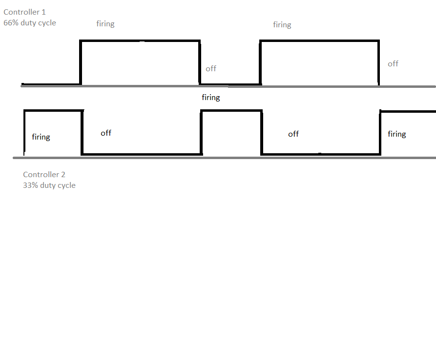
PID waveform.png
 
Last edited:
If you are handy with electronics, or good at google, you can find an interlock circuit or device that will prevent a signal from being ON in the presence of another one being ON. Can be done with some simple transistors.

Also, and not trying to sound d!ckish here, but “firing” is not really a state in electronics. Just go ahead and use ON and OFF.
 
use one PID along with two ssr relays; a normally closed relay and a normally open.
that would give you the behavior shown in your graph.
 
Yes an interlock circuit would prevent them from firing at the same time, but not guarantee synchronicity. And yes, the one PID option wouldnt work.

bump for other eyes.

edit* brunDog: is there a way to give priority to one side of the circuit when designing an interlock? Because I could leave one side at 100% duty cycle, and just adjust the duty cycle of the other PID controller, but have it have priority, so that whenever it wants to fire, the other has to turn off?
 
Yes, one would need to be the priority device. For example, say PID1 -> SSR1 has priority. Then the second circuit would be PID2 -> Interlock -> SSR2. When PID1 is ON, then the interlock is active and the ON signal from PID2 cannot reach SSR2. If PID1 is OFF, then the signal from PID2 passes through to SSR2.

If I were being nitpicky, the interlock would have a small timeout associated with it (5 ms) to ensure the first element is actually turned off be the second turns on.

Shameless plug: we have this type of functionality planned for BruControl... it’s just not set for release with v1.1 but will in v1.2.
 
Okay cool, I'll look into the interlock circuitry more.

As for the software, I actually have a control system that I have programmed myself, running on a TI MSP platform. I havent had a chance to test the full operation of the program as far as controlling the outputs to pumps and elements yet because I havent had my panel built up to a state of functionality yet (almost there though, maybe another month), but through forcing inputs i have been able to transition all the way through a simulated brew cycle. Shoot me a PM and i'd love to talk more about programming control systems with you.
 
If you are programming it, just add the interlock in code!

I will eventually. Im going to build out the panel completely first, that way i'll have a fully functional panel and can test little bits of the code at a time and still have a functional control panel.
 
interlock circuit prelim.png
So here is a preliminary diagram of what ive come up with.

It starts with 2, 3 position NO-off-NO switches. The first switch either closes both NO contactors, or powers the second switch. The second switch allows you to chose between the two NO contactors individually. Then i have a second contactor, this one NC, in series with the HLT Contactor, and the coil of this contactor is wired to the output of the Boil kettle PID controller.

For this to work properly, the HLT PWM should be set at 100%. Then, because the second contactor is NC and driven by the second PWM, when the boil kettle PWM goes high, it will open the second contactor, shutting off the voltage to the HLT element, while allowing the SSR to pass the voltage through to the kettle element.

Am i missing something here, or does this look okay to you guys?
 
You can't use relays for this application. The NC relay will toggle on off every second or whatever your PWM period is set to.
 
You can't use relays for this application. The NC relay will toggle on off every second or whatever your PWM period is set to.
That is what i want it to do though. I want the PID output of the boil kettle to toggle off the output to the HLT. granted i realize that constant switching like that will wear out the unit, but I only plan on using this feature when I am doing back to back batches so it wont be an every brew use.
 
Back
Top