Stc-1000+

Homebrew Talk - Beer, Wine, Mead, & Cider Brewing Discussion Forum

Help Support Homebrew Talk - Beer, Wine, Mead, & Cider Brewing Discussion Forum:

This site may earn a commission from merchant affiliate links, including eBay, Amazon, and others.
Fair enough - Honestly, I didn't click on the link for the store with the big "Sold Out" words on the front page. Thanks for the info.


Yeah, I suppose I should change that. I only have 20 or so units left , though, so not going out of my way to advertise them.


Sent from my iPhone using Home Brew
 
2 questions.

1. Someone was looking at pining out the relay control to be able to drive 5 volt
things (fan?) when the relay is enabled. I can't find the response that talks about this.
Was this feasible ?

2. Alpha mentioned that a serial clock/data stream could be generated from the STC,
sending out the temperature to anything that was listening. Was this implemented ?

I've been having issues with my refrigerator icing up, due to all the moisture in the air.
I was looking at making a temp logger with a small screen to show trends. Just thoughts
on how to make use of what is available right now.
 
2 questions.

1. Someone was looking at pining out the relay control to be able to drive 5 volt
things (fan?) when the relay is enabled. I can't find the response that talks about this.
Was this feasible ?

I was in on some discussion regarding relays, and bypassing them. The relay drive circuit is 12vdc, and not likely capable of driving a fan. You certainly could drive a 5vdc fan with the relay output contacts, but you'd have to supply the 5vdc.
 
Thanks.
I need 120v and 5/12volt outputs based on the same control for turning on the refrigerator and a fan.

So I'd have to add relays to the solution.
 
Thanks.
I need 120v and 5/12volt outputs based on the same control for turning on the refrigerator and a fan.

So I'd have to add relays to the solution.

Not quite sure what you mean. If you use the relay output contacts to feed 120v to a duplex receptacle you can plug in the fridge and a 5v phone charger (ie USB charger) to run the fan. Done. When the STC calls for cooling the refrigerator and fan both come on. This assumes the fridge uses less than 10 amps. If more, your'll need a higher current external relay.

The 12v is what the STC uses to energize it's relay internally.
 
Yes, what you suggest is true. I have that setup mostly now with thermostat, SS relay, power strip.

I was trying to simplify fan power, figuring that there would be enough put out by the board
to drive a 20ma fan. This is because I have a 2 chamber fermentation cabinet and will
need 2 STCs and associated equipment.

If the board could drive the fans, then the system cleans up nicely. 120v power goes to each STC. STC outputs 120v for heater and fridge, and 12v to drive fans.
 
.... and 12v to drive fans.

Not likely. The 12v relay drive circuit is designed to drive the relay, and nothing else. If you tap into it to drive the fans it's probably going to fail, or just not work.

You might be able to use the 12v supply (not 12v relay driver) but that would be on 100% of the time, even when the STC is 'off'.
 
fantastic, thank you very much. I would like to ask you a favor. It would be possible to write a much more simple firmware, without stages, only the possibility to set via the buttons both the temperature and the time? thank you very much again.
 
fantastic, thank you very much. I would like to ask you a favor. It would be possible to write a much more simple firmware, without stages, only the possibility to set via the buttons both the temperature and the time? thank you very much again.

Sure it would be possible.
All the source code is open source and available on GitHub. I even provide hints for how to develop and perform the build in the user manual.
You are free to modify it to you liking.
 
Yes, what you suggest is true. I have that setup mostly now with thermostat, SS relay, power strip.

I was trying to simplify fan power, figuring that there would be enough put out by the board
to drive a 20ma fan. This is because I have a 2 chamber fermentation cabinet and will
need 2 STCs and associated equipment.

If the board could drive the fans, then the system cleans up nicely. 120v power goes to each STC. STC outputs 120v for heater and fridge, and 12v to drive fans.

You can build your additional fan-powering circuit with 1 or 2 transistors and a few resistors, and drive it from the 12V relay tap. You can even build a timer/delay in it so it stays on longer, after the relay clicks off.
 
You can build your additional fan-powering circuit with 1 or 2 transistors and a few resistors, and drive it from the 12V relay tap. You can even build a timer/delay in it so it stays on longer, after the relay clicks off.

That is a cool idea. For the timer part, I wonder if a suitably large capacitor on the input to the transistor would suffice. You might want to sub the transistor for a darlington transistor though or even a FET, if you try that route though. You don't want to drive the transistor in the linear region.
 
That is a cool idea. For the timer part, I wonder if a suitably large capacitor on the input to the transistor would suffice. You might want to sub the transistor for a darlington transistor though or even a FET, if you try that route though. You don't want to drive the transistor in the linear region.

you might be able to use a FET or BJT with an RC circuit to control it, but you will be in the linear region for some amount of time. Effects on the fan would just mean it will slow down before it stops.

Personally I would use a 555. cheap and easy and provides a nice digital output for the transistor.

Yeah, that would probably be a better idea.
 
I'm wondering if anyone could help me with ramping. I have an ale that has completed fermentation and I am attempting to cold crash. I setup a simple program, ramping from 60 to 37.5 over three days and hold.

Pr0 (SP0 = 60 dh0 = 72, SP1 = 37.5 dh1 = 0)
rP = 1
rn = Pr0

The program is running as it moved the temp from 65 to 60 but has held at 60 for 24 hours. I have checked that ramping (rn) is set to 1. Has anyone else experienced this type of issue? I running version 1.05.

Thanks..
 
Last edited by a moderator:
I'm wondering if anyone could help me with ramping. I have an ale that has completed fermentation and I am attempting to cold crash. I setup a simple program, ramping from 60 to 37.5 over three days and hold.

Pr0 (SP0 = 60 dh0 = 72, SP1 = 37.5 dh1 = 0)
rP = 1
rn = Pr0

The program is running as it moved the temp from 65 to 60 but has held at 60 for 24 hours. I have checked that ramping (rn) is set to 1. Has anyone else experienced this type of issue? I running version 1.05.

Thanks..


Hate to answer my own post but I recycled the power. Then set rP=0 and then back to rP=1. Seems to be working.
 
Got my flashed stc-1000 from will earlier this week, been having fun, such an awesome controller.

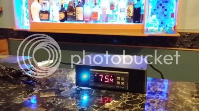
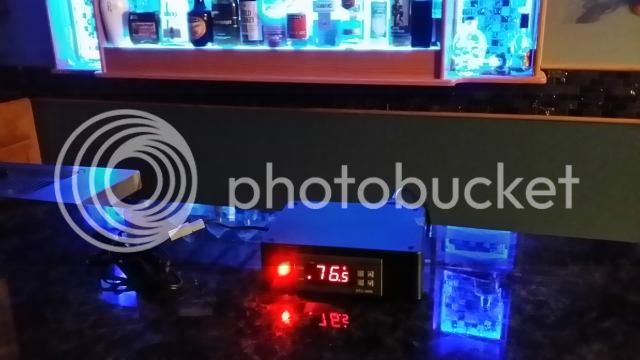
I got bored tonight and put a connector on the temp sensor, and added a 5mm tri-color LED. Taking pictures of LED's can be a bit hard to get right, these didn't turn out that great.

Cooling mode:


Heating mode:


I'm wondering if anyone could help me with ramping. I have an ale that has completed fermentation and I am attempting to cold crash. I setup a simple program, ramping from 60 to 37.5 over three days and hold.

Pr0 (SP0 = 60 dh0 = 72, SP1 = 37.5 dh1 = 0)
rP = 1
rn = Pr0

The program is running as it moved the temp from 65 to 60 but has held at 60 for 24 hours. I have checked that ramping (rn) is set to 1. Has anyone else experienced this type of issue? I running version 1.05.

Thanks..

Hi!
It sounds like you got the right settings. You say temp is not dropping like it should, but what is the actual SP value?
Check SP value by pressing up button and the profile (down button). If the values seem correct, then it is likely something with your setup (does it go below 60?).
It could be a bug as well, but no one else has reported this issue and 1.05 has been out a while.
 
Hi guys!
Ok, so I have pushed an additional change to the work branch.
I changed the SA (or setpoint alarm setting). I decided it was a too complicated, and not versatile or intuitive enough.

So, I changed this setting to be settable from -80.0 to 80.0 degF (or -40.0 to 40.0 degC, as if you guys care...). What this does, is that if this setting is positive, then it is the allowable setting, by how much the temperature is allowed to differ from the setpoint before the alarm goes off. For ex. say you set it at 5.0, then the alarm will sound if temperature is 5.0 degrees (or more) above OR below setpoint.
If the setting is negative, say -5.0 degrees, then the alarm will sound if the temperature IS NOT 5.0 degrees (or more) above OR below the setpoint.
The first case can be useful during fermentation, to warn if temperature is out of range. The second case can be useful to get a reminder once wort has reached pitching temp.

If it is set at 0.0, the alarm is completely disabled.

If the alarm is tripped, the buzzer will sound and the display will flash between current temperature and "SA" as an indication. It will not disengage the relays as the sensor failure alarm ("AL"), and the unit will still function as normal (only a bit more annoyingly).

Care will be needed in selecting the correct value to avoid tripping the alarm unnecessarily. Especially when running profiles, as the setpoint will change (and even more so without ramping or with steep ramps, as SP will change much).

Just want to make sure I undestand the alarm setting for knowing when you're at pitching temperature. If SA is set to -0.1, then the alarm will sound when the temperature reaches SP+0.1 when cooling down to SP. Is this correct?
 
Just want to make sure I undestand the alarm setting for knowing when you're at pitching temperature. If SA is set to -0.1, then the alarm will sound when the temperature reaches SP+0.1 when cooling down to SP. Is this correct?


Yes, though it's technically SP ±0.1, so you only would have a 0.2 degree window for it to alarm in. You might want to set it a bit broader if your cooling system is faster than the STC's polling or resolution.

Oh and the alarm is surprisingly loud - I found out this past Sunday morning.
 
That is 100% correct ClunkClunk. It might be a good idea to set the absolute value of SA larger than the hy setting.
Hope it didn't ruin your Sunday :)
 
Hi!

It sounds like you got the right settings. You say temp is not dropping like it should, but what is the actual SP value?

Check SP value by pressing up button and the profile (down button). If the values seem correct, then it is likely something with your setup (does it go below 60?).

It could be a bug as well, but no one else has reported this issue and 1.05 has been out a while.


I think it just got hung up for some reason. Not really sure but recycling everything seems to have it working again.

Your software is fantastic. Thanks for all the hard work.
 
Hope it didn't ruin your Sunday :)

Not in the slightest! I was actually a bit concerned I wouldn't hear the alarm as I hadn't tested it before actually relying on it, and my fermentation fridge is in the garage.

I had a late night brew and chilled as much as our 80F groundwater would allow in a reasonable amount of time, then stuck the fermenter in the fridge and set the alarm for 60F ± 3 degrees.

Went to bed, and the following morning after I had some coffee, I heard the alarm go off even though my fermentation fridge was in the garage and I was inside. Nice and loud.
 
Today I got in two more units from will, thank you sir. In preparation for the flashing hardware coming soon I unsoldered the programming holes, man what a pain. I had the best luck tipping the board on its side, holding the iron on the top while hitting the back with the solder sucker.
 
I've finally got the hang of clearing the holes. I found the key to be to use a slightly hotter iron. I suck from the same side (bottom) Tilt the iron and use just the very tip, when the solder melts quickly use the solder sucker without removing the iron.
This works so well, I usually clear the holes in a minute. I actually think it is harder now to add the pinrow header, as it wants to fall out of the 'too well' cleared holes.
 
That will work as well, and I used to do it like that. But if you get the technique down with the sucker, you clear the holes so fast and easy... My problem was not using hot enough iron.
 
Ahhh... Sorry :) Yeah, I usually try to jam a toothpick between the header and the MCU to keep it in place. As a bonus, that makes the header tilt outwards and makes it easier to insert the programmer connector.
 
Out of curiosity, are many adding features like 12v for constant on fan etc to their setups? I am going to work on building up some pre-assembled boxes, and just curious if something like the tri color LED as an option, or a constant 12v source plug etc would be things many are interested in?


Got my flashed stc-1000 from will earlier this week, been having fun, such an awesome controller.

I got bored tonight and put a connector on the temp sensor, and added a 5mm tri-color LED. Taking pictures of LED's can be a bit hard to get right, these didn't turn out that great.

Cooling mode:


Heating mode:


The first thing that comes to my mind looking at those pics, is that the box seems very suitable to house a DIY stir plate :)
I realise it won't fit with the STC, but if you source the boxes anyway., maybe you could whip up some stir plates while your at it.
A computer fan, some neodymium magnets, a power jack and one of these and you got yourself a damn nice stirplate. These dimmers are awesome, I use them to regulate speed on solar pumps as well. You can take it apart and mount the pot in your enclosure by just drilling a hole.

Edit: Oh, and also... No pics of the backside of your build, but make sure to include a fuse.
 
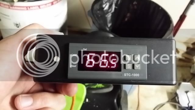
Couple of other pics, this over I used a razor blade to figure out where to put things, pretty rough, but am having the cases machined on a cnc to make it much cleaner and faster

20140920_205831.jpg


20140920_205927.jpg
 
Ok. I'm no electrician, but my idea would be to use a much smaller fuse for the inlet to the STC.
The fridge (and heater) should be protected by the main fuse. If the user wants properly rated fuses for their load, then they'd need to fix that themselves, as you cannot possibly know that. I suppose you could have 3 fuses in the box (STC, heat and cool) if there is space and then ship heat and cool with 10amp fuses.
 
The first thing that comes to my mind looking at those pics, is that the box seems very suitable to house a DIY stir plate :)
I realise it won't fit with the STC, but if you source the boxes anyway., maybe you could whip up some stir plates while your at it.
A computer fan, some neodymium magnets, a power jack and one of these and you got yourself a damn nice stirplate. These dimmers are awesome, I use them to regulate speed on solar pumps as well. You can take it apart and mount the pot in your enclosure by just drilling a hole.

Edit: Oh, and also... No pics of the backside of your build, but make sure to include a fuse.


Alphaomega I got one of those a while back to try to control my 12v solar pumps. It didn't work at all. I could dim an led but the ussolarpumps use some kind of internal chip that try's to run the pump at full speed no matter how much voltage they are getting. I tried different configurations but could never get that dimmer to work as a speed control.
 
Strange. I doubt there is any 'logic' to those pumps, but maybe they dont work well with pwm drive due to the specs, at least at the frequency the LED dimmer put out.
I use them with the beige pumps and it works absolutely great.
 
Back
Top