RIMS + Fermenters Control panel schematic help

Homebrew Talk - Beer, Wine, Mead, & Cider Brewing Discussion Forum

Help Support Homebrew Talk - Beer, Wine, Mead, & Cider Brewing Discussion Forum:

This site may earn a commission from merchant affiliate links, including eBay, Amazon, and others.

staffordj

Supporting Member
HBT Supporter
Joined
Oct 25, 2008
Messages
146
Reaction score
22
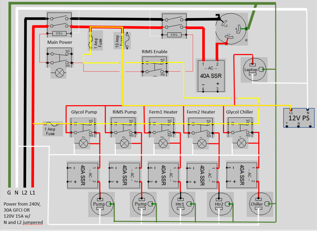
I built a air conditioning unit based glycol system for two fermenters several years ago. I am working on adding a RIMS to this setup and am redoing the control panel from scratch. I have read a lot of threads here and have leveraged heavily from doug293cz's great work (OK, stolen or plagiarized is probably more accurate). In this case, I am looking to be able to plug into 120V to control the fermenters (AC unit, pump, flexwatt heater tape) OR plug into 240V when mashing for the RIMS. The main reason is the 240V is across the garage from where the fermenters sit, and I want to just be able to connect a cable when brewing and need the RIMS to 240V, but not have to move the 240V recepticle. The fermenters are next to 120V power. My control panel will have one L14-30 input. I will have a pigtail to connect to 120V and will tie Line2 and neutral together. I am hoping to get some help from the community to make sure I have this right.
Here is the HV wiring:
1622664900474.png
 
Most of it looks good.

You don't need to jumper N to L2 on your pigtail, unless you want to use the RIMS power outlet when plugged into a 120V outlet. Jumpering won't hurt anything in any case.

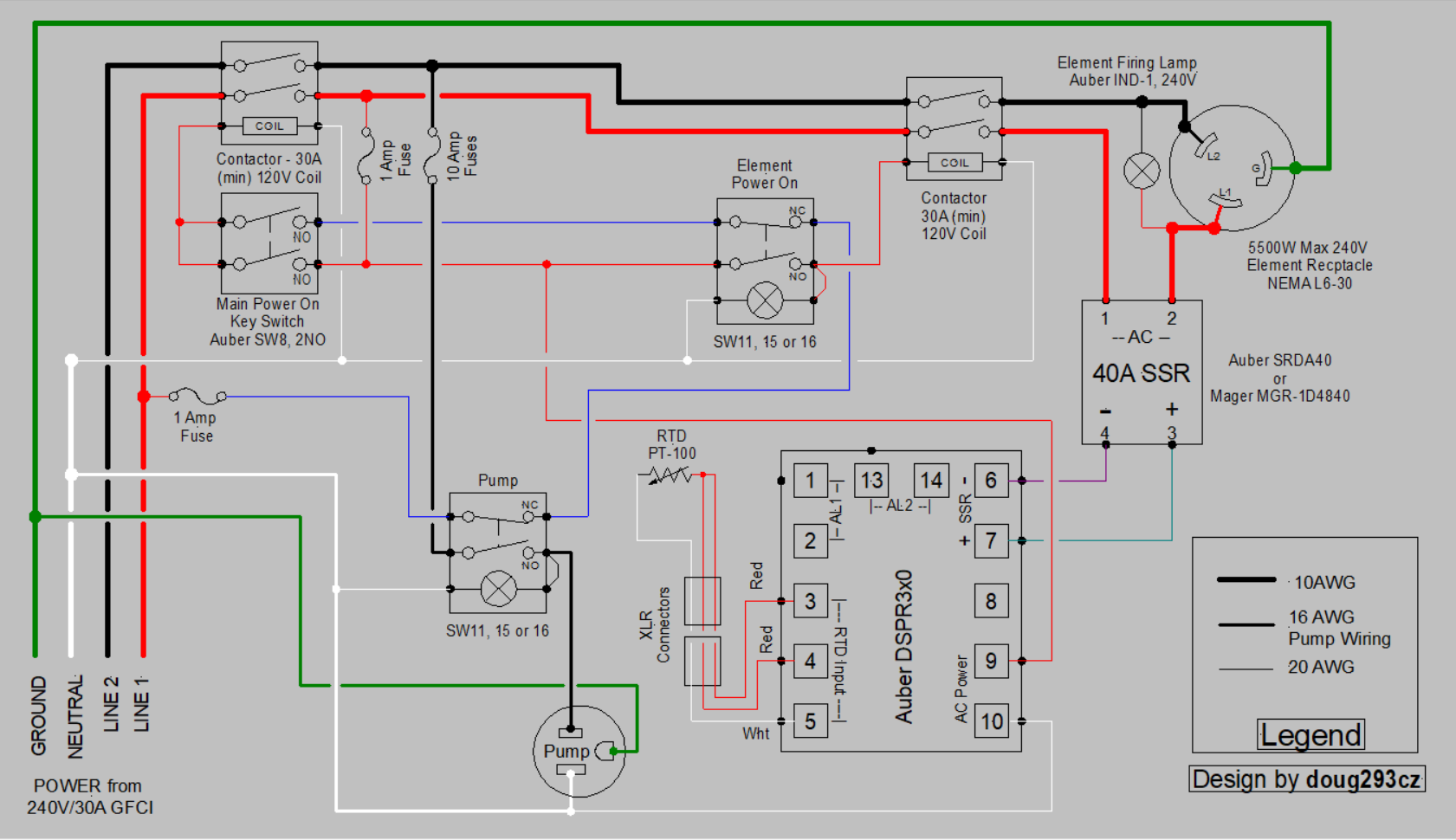
Your safe start interlock is implemented in a less than optimal way, although it will work (the circuit as drawn will power the 12VDC power supply when the main power is off.) The implementation shown below is a bit cleaner IMO. Difference is in the way the main power switch is wired.

DSPR300 1-Pump 1-Element 240V rev-2.PNG


10A may not be enough when you are running the chiller, chiller pump, and possibly one heater all at once (for example when ferm 1 needs cooling, but ferm 2 doesn't.) I'd recheck the potential current loads - you may need to go to 15A or even 20A.

Brew on :mug:
 
Thanks, I appreciate you taking a look. I am not sure I understand your comment on the 12V. It is pulling from downstream of the main contactor which should require the main switch to be on. What am I missing?

I agree on the 10A. I will check what the circuit breaker it has been running on in my current setup. I think 15A, but maybe 20A.
 
Jumping into this thread to ask a question about the schematic in post #2...

Could this panel design be altered in order to power a 120V system or a 240V system? My thought is to change the element power switch to a 3-position selector with two pairs of stacked NO and NC blocks. Turn the selector switch to the 240V option and the circuit is identical to what is already in the schematic. For 120V operation, turning the selector switch to the other direction would activate a mini power relay along L2 between the main power contactor and the element contactor that would change one leg of the element to neutral.

Would that work?
Yes.

Brew on :mug:
 
Ok great.

Follow-up: Could a controller as I described above be powered by a 120V/15A circuit?

I'm pretty sure that if you used an adapter plug to power this using a 120V/15A circuit, the pump wouldn't work. Am I correct that the pump would have to be connected to L1 instead of L2? That's assuming that the plug adapter connects the neutral and L2 connections.
Yes, you can power from a 15A/120V circuit, as long as the element is rated under 1650W@120V or 66000W@240V.

Yes the pump would need to be connected to L1.

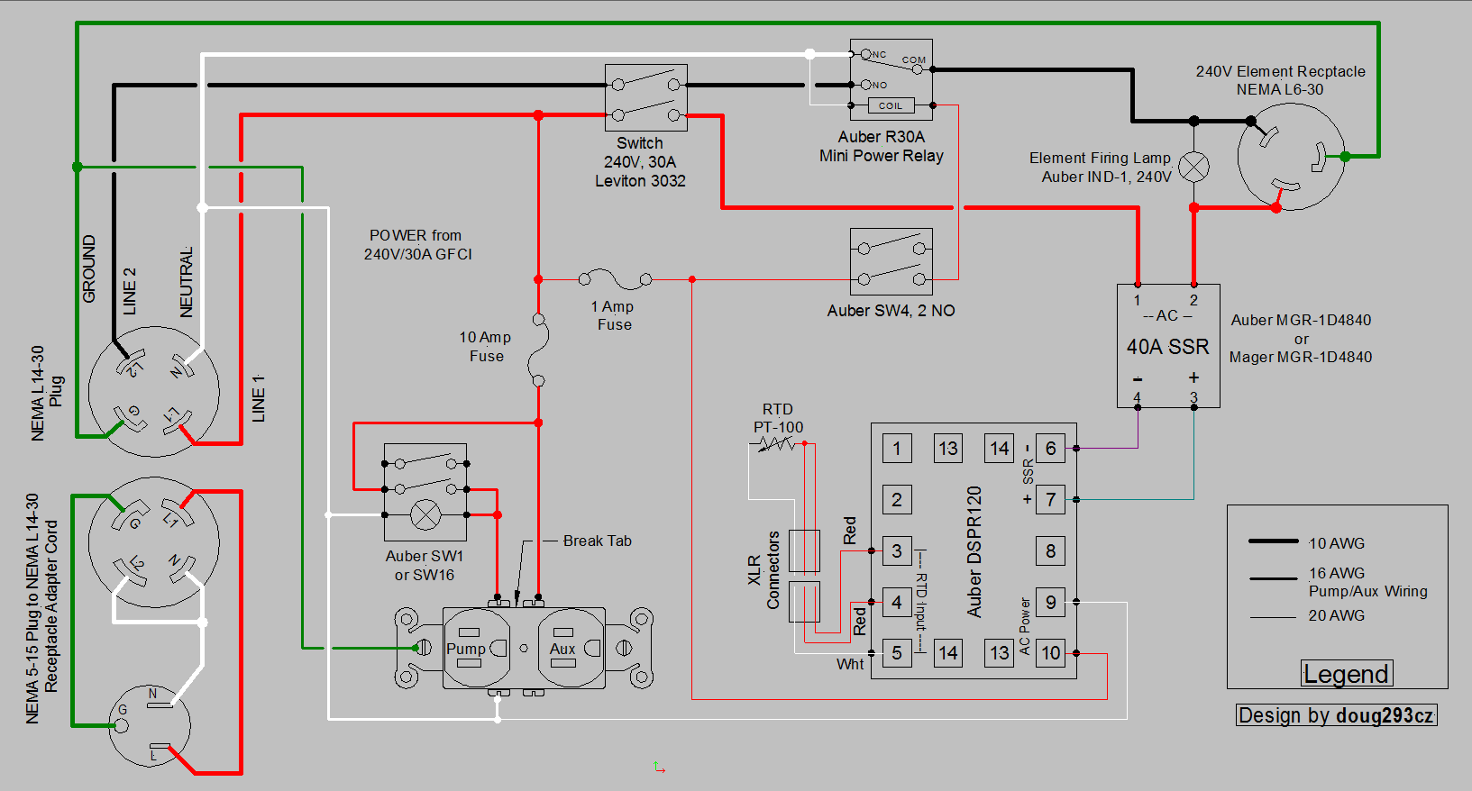
Here's a design I did a while back, that doesn't use contactors, so it couldn't have a safe start interlock. It shows how to make a pigtail adapter for the 240V plug cord.

DSPR120 1-Pump 1-Aux Dual Voltage Input Output.PNG


Brew on :mug:
 
Hey again, I realized I made a mistake in my circuit schematic. I had the boil contactor coil and relay coil in parallel which means the relay would have been activated regardless of the position of the 3-position selector and obviously that’s not the idea… So my question is if I can put the relay coil and boil contactor coil in series along one output of the selector switch? I’m worried that it won’t work since both are 110-V coils.

I could also just add another NO switch block on the 120-V side of the selector and use that to activate the relay coil.
Can you post a schematic of what you did?

Brew on :mug:
 
Sure.

This is the incorrect schematic:
eBIAB circuit (1).png

(The element firing LED has been omitted as well as the connection between the PID and SSR.)

Here's the change I suggested in my above post:
eBIAB circuit (2).png
 
Sure.

This is the incorrect schematic:
View attachment 737882
(The element firing LED has been omitted as well as the connection between the PID and SSR.)

Here's the change I suggested in my above post:
View attachment 737883
You know the first one doesn't work, and the modified one doesn't either. It is possible to get this switch configuration to do what you want, but you have to think out of the box. Instead of thinking of the switch as ON-OFF-ON (off in the middle position), think of it as an OFF-ON-ON switch. Off in the left or down position, element contactor on in the center position, and element contactor plus voltage selection relay activated in the right or up position. See if you can figure it out. Let me know if you need more help.

Brew on :mug:
 
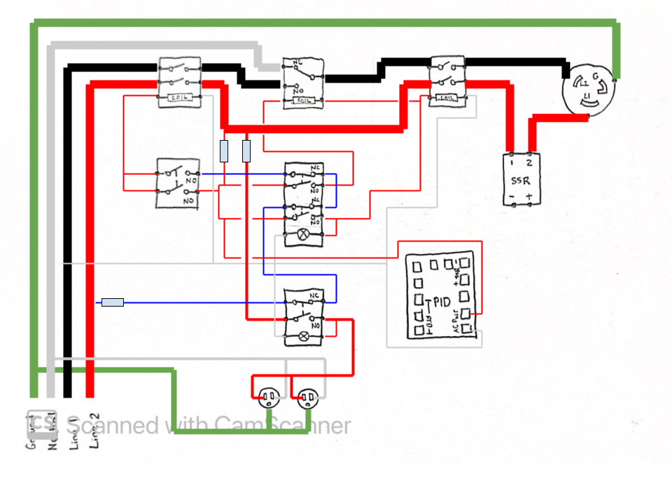
The top NC block controls the element coil and the bottom NO block controls the relay coil. The middle blocks are connected in series for the interlock.
eBIAB circuit (4).png

Thanks for your help again! I'm a physics teacher and I love problems that can be solved with out-of-the-box thinking. From a pedagogical perspective, the way you framed your last response was A+
👍😁
 
The top NC block controls the element coil and the bottom NO block controls the reView attachment 737923View attachment 737923lay coil. The middle blocks are connected in series for the interlock.
Thanks for your help again! I'm a physics teacher and I love problems that can be solved with out-of-the-box thinking. From a pedagogical perspective, the way you framed your last response was A+
👍😁
It's upside down from how I was visualizing it, but the electrons don't care. I think it's correct.

Curious why you have two "pump" outlets switched by one switch.

Brew on :mug:
 
It’s mostly for the flexibility of an additional outlet. I’ve considered trying a two-vessel set up and this would allow me to run a second pump. This panel only has one element output of course so I’d build a small variable power source to run the second element - it would be a 1650-W element so I’d run it off a different 120V circuit.
 
It’s mostly for the flexibility of an additional outlet. I’ve considered trying a two-vessel set up and this would allow me to run a second pump. This panel only has one element output of course so I’d build a small variable power source to run the second element - it would be a 1650-W element so I’d run it off a different 120V circuit.
Normally, if you run two pumps, they would be controlled with separate switches. If you just want one pump and an aux outlet, then the pump outlet would be switched, and the aux outlet un-switched. It's switching both outlets with a single switch that confuses me.

Brew on :mug:
 
Normally, if you run two pumps, they would be controlled with separate switches. If you just want one pump and an aux outlet, then the pump outlet would be switched, and the aux outlet un-switched. It's switching both outlets with a single switch that confuses me.

Brew on :mug:

That makes sense. When I wire it up, I’ll make one unswitched. Thanks for the advice again.
 
Back
Top